Computer SUZUKI SWIFT 2008 2.G Service Workshop Manual
[x] Cancel search | Manufacturer: SUZUKI, Model Year: 2008, Model line: SWIFT, Model: SUZUKI SWIFT 2008 2.GPages: 1496, PDF Size: 34.44 MB
Page 11 of 1496

Downloaded from www.Manualslib.com manuals search engine Precautions: 00-6
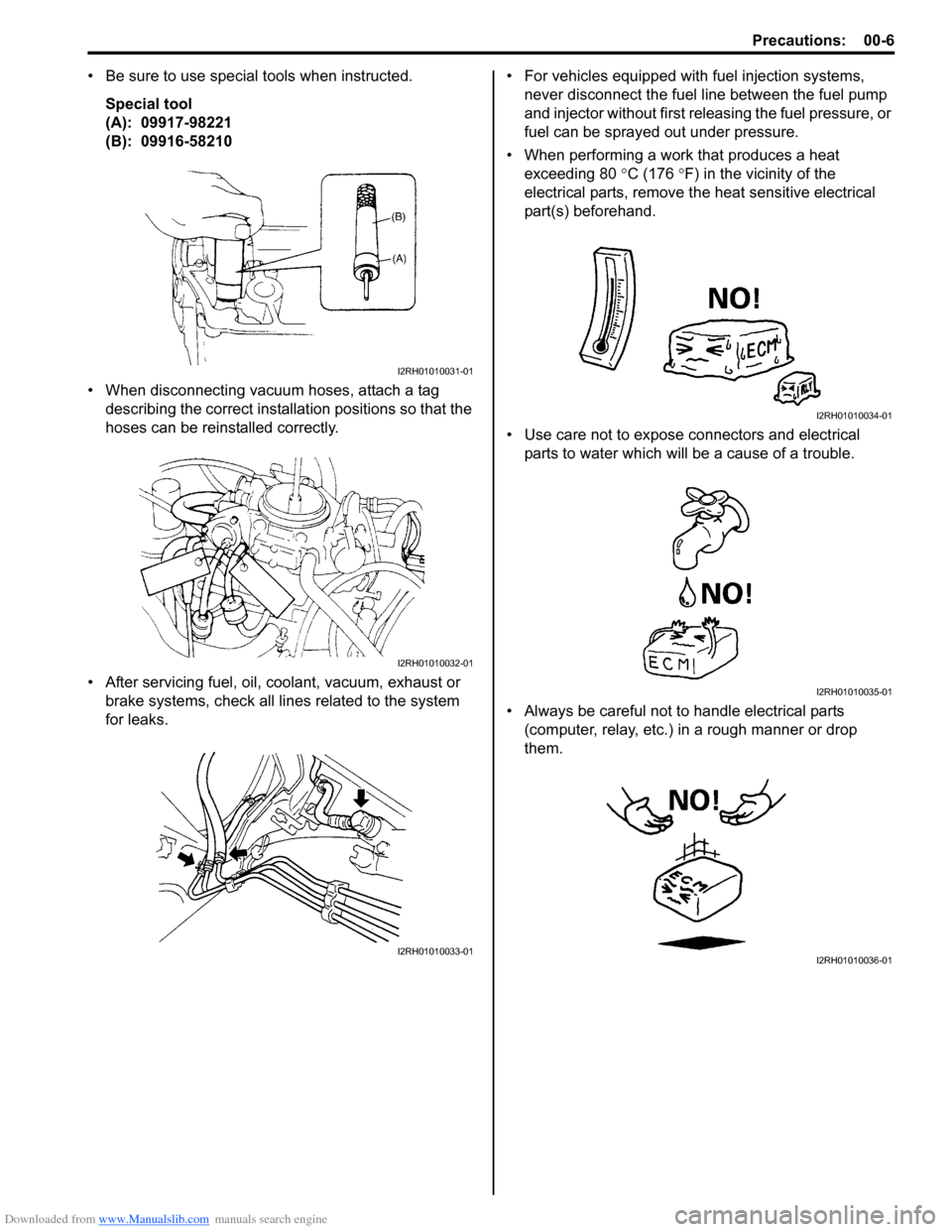
• Be sure to use special tools when instructed.Special tool
(A): 09917-98221
(B): 09916-58210
• When disconnecting vacuum hoses, attach a tag describing the correct installation positions so that the
hoses can be reinstalled correctly.
• After servicing fuel, oil, coolant, vacuum, exhaust or brake systems, check all lin es related to the system
for leaks. • For vehicles equipped with fuel injection systems,
never disconnect the fuel line between the fuel pump
and injector without first releasing the fuel pressure, or
fuel can be sprayed out under pressure.
• When performing a work that produces a heat exceeding 80 °C (176 ° F) in the vicinity of the
electrical parts, remove t he heat sensitive electrical
part(s) beforehand.
• Use care not to expose connectors and electrical parts to water which will be a cause of a trouble.
• Always be careful not to handle electrical parts (computer, relay, etc.) in a rough manner or drop
them.
I2RH01010031-01
I2RH01010032-01
I2RH01010033-01
I2RH01010034-01
I2RH01010035-01
I2RH01010036-01
Page 14 of 1496

Downloaded from www.Manualslib.com manuals search engine 00-9 Precautions:
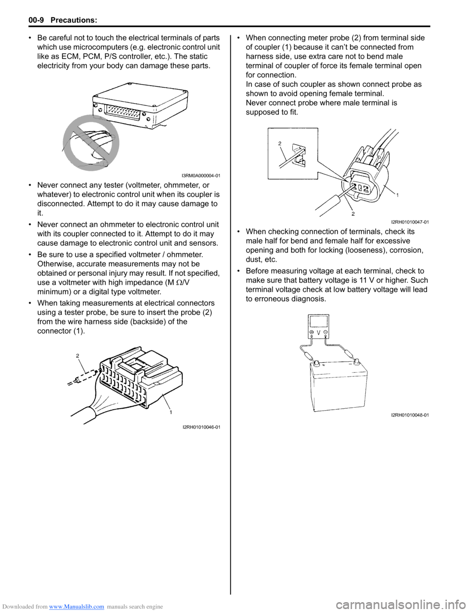
• Be careful not to touch the electrical terminals of parts which use microcomputers (e.g. electronic control unit
like as ECM, PCM, P/S controller, etc.). The static
electricity from your body can damage these parts.
• Never connect any tester (voltmeter, ohmmeter, or whatever) to electronic control unit when its coupler is
disconnected. Attempt to do it may cause damage to
it.
• Never connect an ohmmeter to electronic control unit with its coupler connected to it. Attempt to do it may
cause damage to electronic control unit and sensors.
• Be sure to use a specified voltmeter / ohmmeter. Otherwise, accurate measurements may not be
obtained or personal injury ma y result. If not specified,
use a voltmeter with high impedance (M Ω/V
minimum) or a digital type voltmeter.
• When taking measurements at electrical connectors using a tester probe, be sure to insert the probe (2)
from the wire harness side (backside) of the
connector (1). • When connecting meter probe (2) from terminal side
of coupler (1) because it can’t be connected from
harness side, use extra care not to bend male
terminal of coupler of force its female terminal open
for connection.
In case of such coupler as shown connect probe as
shown to avoid opening female terminal.
Never connect probe where male terminal is
supposed to fit.
• When checking connection of terminals, check its
male half for bend and female half for excessive
opening and both for locking (looseness), corrosion,
dust, etc.
• Before measuring voltage at each terminal, check to make sure that battery voltage is 11 V or higher. Such
terminal voltage check at lo w battery voltage will lead
to erroneous diagnosis.
I3RM0A000004-01
I2RH01010046-01
I2RH01010047-01
I2RH01010048-01
Page 62 of 1496

Downloaded from www.Manualslib.com manuals search engine 1A-12 Engine General Information and Diagnosis:
Electronic Control System DescriptionS7RS0B1101011
The electronic control system consists of 1) various sensors which detect the state of engine and driving conditions, 2)
ECM which controls various devices ac cording to the signals from the sensors and 3) various controlled devices.
Functionally, it is divided into the following sub systems:
• Fuel injection control system
• Ignition control system
• Electric throttle body control system
• Fuel pump control system
• Radiator cooling fan control system
• Evaporative emission control system
• EGR system
• Oxygen sensor heater control system
• A/C control system (A/C model)
• Camshaft position control system
• Immobilizer control system
• Generator control system
• Controller (computer) communication system
Especially, ECM, BCM, combination meter, TCM (A/T model), ABS/ESP ® control module, steering angle sensor
(ESP® model) and keyless start control module (if equipped) intercommunicate by means of CAN communication.