Cylinder compression SUZUKI SWIFT 2008 2.G Service Workshop Manual
[x] Cancel search | Manufacturer: SUZUKI, Model Year: 2008, Model line: SWIFT, Model: SUZUKI SWIFT 2008 2.GPages: 1496, PDF Size: 34.44 MB
Page 47 of 1496

Downloaded from www.Manualslib.com manuals search engine Table of Contents 1-iii
EVAP Canister Purge Valve and Its Circuit
Inspection.......................................................... 1B-2
Vacuum Passage Inspection .............................. 1B-3
Vacuum Hose and Purge Valve Chamber Inspection.......................................................... 1B-3
EVAP Canister Purge Valve Inspection .............. 1B-3
EVAP Canister Inspection ... ................................ 1B-4
EGR Valve Removal and Installation .................. 1B-4
EGR Valve Inspection ......................................... 1B-4
PCV Hose Inspection .......................................... 1B-4
PCV Valve Inspection ......................................... 1B-5
Special Tools and Equipmen t ............................. 1B-5
Special Tool ........................................................ 1B-5
Engine Electrical Devices .. ..................... 1C-1
Repair Instructions .............................................. 1C-1
ECM Removal and Installation ............................ 1C-1
MAP Sensor Inspection ...................................... 1C-2
Electric Throttle Body Assembly On-Vehicle
Inspection.......................................................... 1C-2
Electric Throttle Body System Calibration ........... 1C-5
APP Sensor Assembly On-V ehicle Inspection .... 1C-5
APP Sensor Assembly Removal and Installation ......................................................... 1C-5
APP Sensor Assembly Inspection ...................... 1C-6
ECT Sensor Removal and In stallation ................ 1C-6
ECT Sensor Inspection ....................................... 1C-7
HO2S-1 and HO2S-2 Heater On-Vehicle Inspection.......................................................... 1C-7
HO2S-1 and HO2S-2 Removal and Installation ......................................................... 1C-7
CMP Sensor Removal and In stallation ............... 1C-8
Camshaft Position (CMP) Se nsor Inspection ...... 1C-8
CKP Sensor Removal and Installation ................ 1C-9
CKP Sensor Inspection ....................................... 1C-9
Knock Sensor Removal and Installation ........... 1C-10
Main Relay, Fuel Pump Relay and Starting
Motor Control Relay Inspection....................... 1C-10
MAF and IAT Sensor On-Vehicle Inspection .... 1C-11
MAF and IAT Sensor Removal and Installation ....................................................... 1C-11
MAF and IAT Sensor Inspection ....................... 1C-12
Electric Load Current Sensor On-Vehicle Inspection........................................................ 1C-12
Specifications ..................................................... 1C-13
Tightening Torque Specifications ...................... 1C-13
Engine Mechanical ......... ......................... 1D-1
General Description ............................................. 1D-1
Engine Construction Description ......................... 1D-1
Camshaft Position Control (VVT Variable Valve Timing) System Description .................... 1D-2
Diagnostic Information and Procedures ............ 1D-4 Compression Check ............................................ 1D-4
Engine Vacuum Check ....................................... 1D-5
Valve Lash (Clearance) Inspection ..................... 1D-6
Repair Instructions .............................................. 1D-9 Air Cleaner Components ..................................... 1D-9
Air Cleaner Element Removal and Installation .... 1D-9 Air Cleaner Element Ins
pection and Cleaning ..1D-10
Cylinder Head Co ver Removal and
Installation .......................................................1D-10
Throttle Body and Intake Manifold
Components ....................................................1D-12
Throttle Body On-Vehicle Inspection.................1D-13
Electric Throttle Body Assembly Removal and Installation .......................................................1D-13
Throttle Body Cleaning......................................1D-14
Intake Manifold Removal and Installation .........1D-14
Engine Mountings Components ........................1D-16
Engine Assembly Removal and Installation ......1D-17
Timing Chain Cover Components .....................1D-20
Timing Chain Cover Removal and Installation ..1D-21
Timing Chain Cover Inspection .........................1D-23
Oil Control Valve Removal and Installation .......1D-23
Oil Control Valve Inspection ..............................1D-24
Timing Chain and Chain Tensioner Components ....................................................1D-24
Timing Chain and Chain Tensioner Removal and Installation ................................................1D-25
Timing Chain and Chain Tensioner Inspection ..1D-27
Camshaft, Tappet and Shim Components ........1D-28
Camshaft, Tappet and Shim Removal and Installation .......................................................1D-29
Camshaft, Tappet and Shim Inspection ............1D-31
Valves and Cylinder Head Components ...........1D-34
Valves and Cylinder Head Removal and
Installation .......................................................1D-35
Valves and Cylinder Head Disassembly and Assembly.........................................................1D-37
Valves and Valve Guides Inspection.................1D-40
Cylinder Head Inspection . .................................1D-42
Valve Spring Inspection ....................................1D-43
Pistons, Piston Rings , Connecting Rods and
Cylinders Components ....................................1D-44
Pistons, Piston Rings , Connecting Rods and
Cylinders Removal and Installation .................1D-45
Pistons, Piston Rings , Connecting Rods and
Cylinders Disassembly and Assembly ............1D-46
Cylinders, Pistons and Piston Rings Inspection ........................................................1D-47
Piston Pins and Connecting Rods Inspection ...1D-49
Crank Pin and Connecting Rod Bearings Inspection ........................................................1D-50
Main Bearings, Cran kshaft and Cylinder
Block Components ..........................................1D-53
Main Bearings, Cran kshaft and Cylinder
Block Removal and Installa tion .......................1D-54
Crankshaft Inspection .......................................1D-57
Main Bearings Inspection . .................................1D-59
Sensor Plate Inspection ....................................1D-63
Rear Oil Seal Inspection ...................................1D-63
Flywheel Inspection...........................................1D-63
Cylinder Block Inspection ..................................1D-63
Specifications .................... .................................1D-64
Tightening Torque Specifications ......................1D-64
Special Tools and Equipmen t ...........................1D-66
Recommended Service Material .......................1D-66
Special Tool ......................................................1D-66
Page 91 of 1496
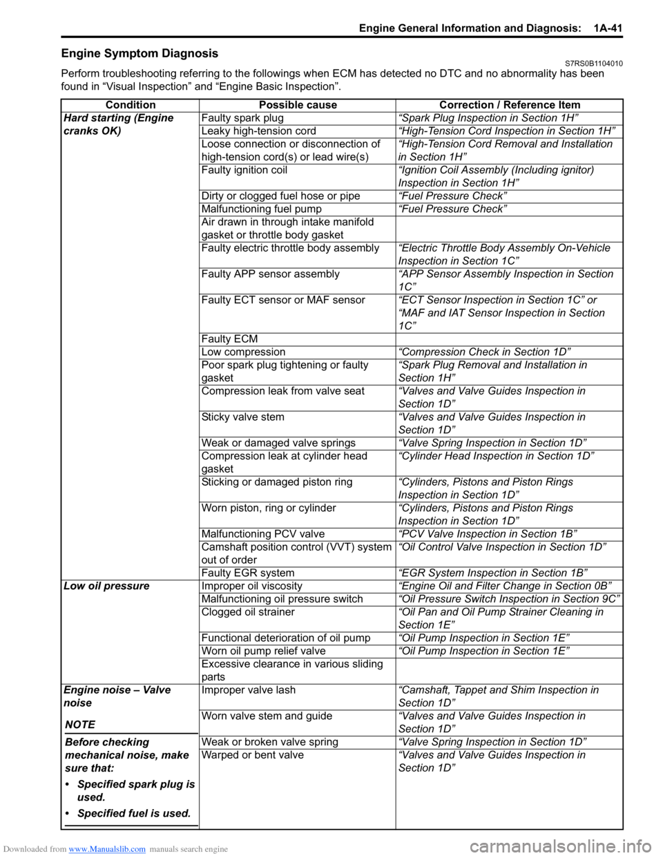
Downloaded from www.Manualslib.com manuals search engine Engine General Information and Diagnosis: 1A-41
Engine Symptom DiagnosisS7RS0B1104010
Perform troubleshooting referring to the followings when ECM has detected no DTC and no abnormality has been
found in “Visual Inspection” and “Engine Basic Inspection”.
Condition Possible cause Correction / Reference Item
Hard starting (Engine
cranks OK) Faulty spark plug
“Spark Plug Inspection in Section 1H”
Leaky high-tension cord “High-Tension Cord Inspection in Section 1H”
Loose connection or disconnection of
high-tension cord(s) or lead wire(s) “High-Tension Cord Removal and Installation
in Section 1H”
Faulty ignition coil “Ignition Coil Assembly (Including ignitor)
Inspection in Section 1H”
Dirty or clogged fuel hose or pipe “Fuel Pressure Check”
Malfunctioning fuel pump “Fuel Pressure Check”
Air drawn in through intake manifold
gasket or throttle body gasket
Faulty electric throttle body assembly “Electric Throttle Body Assembly On-Vehicle
Inspection in Section 1C”
Faulty APP sensor assembly “APP Sensor Assembly Inspection in Section
1C”
Faulty ECT sensor or MAF sensor “ECT Sensor Inspection in Section 1C” or
“MAF and IAT Sensor Inspection in Section
1C”
Faulty ECM
Low compression “Compression Check in Section 1D”
Poor spark plug tightening or faulty
gasket “Spark Plug Removal and Installation in
Section 1H”
Compression leak from valve seat “Valves and Valve Guides Inspection in
Section 1D”
Sticky valve stem “Valves and Valve Guides Inspection in
Section 1D”
Weak or damaged valve springs “Valve Spring Inspection in Section 1D”
Compression leak at cylinder head
gasket “Cylinder Head Inspection in Section 1D”
Sticking or damaged piston ring “Cylinders, Pistons and Piston Rings
Inspection in Section 1D”
Worn piston, ring or cylinder “Cylinders, Pistons and Piston Rings
Inspection in Section 1D”
Malfunctioning PCV valve “PCV Valve Inspection in Section 1B”
Camshaft position control (VVT) system
out of order “Oil Control Valve Inspection in Section 1D”
Faulty EGR system “EGR System Inspection in Section 1B”
Low oil pressure Improper oil viscosity “Engine Oil and Filter Change in Section 0B”
Malfunctioning oil pressure switch “Oil Pressure Switch Inspection in Section 9C”
Clogged oil strainer “Oil Pan and Oil Pump Strainer Cleaning in
Section 1E”
Functional deterioration of oil pump “Oil Pump Inspection in Section 1E”
Worn oil pump relief valve “Oil Pump Inspection in Section 1E”
Excessive clearance in various sliding
parts
Engine noise – Valve
noise
NOTE
Before checking
mechanical noise, make
sure that:
• Specified spark plug is used.
• Specified fuel is used.
Improper valve lash “Camshaft, Tappet and Shim Inspection in
Section 1D”
Worn valve stem and guide “Valves and Valve Guides Inspection in
Section 1D”
Weak or broken valve spring “Valve Spring Inspection in Section 1D”
Warped or bent valve “Valves and Valve Guides Inspection in
Section 1D”
Page 93 of 1496
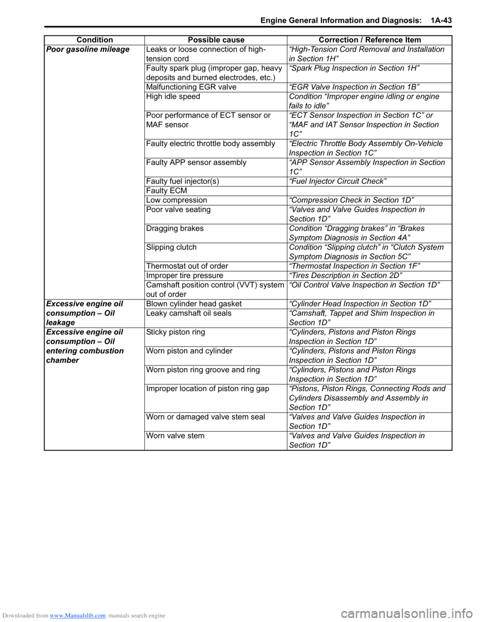
Downloaded from www.Manualslib.com manuals search engine Engine General Information and Diagnosis: 1A-43
Poor gasoline mileageLeaks or loose connection of high-
tension cord “High-Tension Cord Removal and Installation
in Section 1H”
Faulty spark plug (improper gap, heavy
deposits and burned electrodes, etc.) “Spark Plug Inspection in Section 1H”
Malfunctioning EGR valve “EGR Valve Inspection in Section 1B”
High idle speed Condition “Improper engine idling or engine
fails to idle”
Poor performance of ECT sensor or
MAF sensor “ECT Sensor Inspection in Section 1C” or
“MAF and IAT Sensor Inspection in Section
1C”
Faulty electric throttle body assembly “Electric Throttle Body Assembly On-Vehicle
Inspection in Section 1C”
Faulty APP sensor assembly “APP Sensor Assembly Inspection in Section
1C”
Faulty fuel injector(s) “Fuel Injector Circuit Check”
Faulty ECM
Low compression “Compression Check in Section 1D”
Poor valve seating “Valves and Valve Guides Inspection in
Section 1D”
Dragging brakes Condition “Dragging brakes” in “Brakes
Symptom Diagnosis in Section 4A”
Slipping clutch Condition “Slipping clutch” in “Clutch System
Symptom Diagnosis in Section 5C”
Thermostat out of order “Thermostat Inspection in Section 1F”
Improper tire pressure “Tires Description in Section 2D”
Camshaft position control (VVT) system
out of order “Oil Control Valve Inspection in Section 1D”
Excessive engine oil
consumption – Oil
leakage Blown cylinder head gasket
“Cylinder Head Inspection in Section 1D”
Leaky camshaft oil seals “Camshaft, Tappet and Shim Inspection in
Section 1D”
Excessive engine oil
consumption – Oil
entering combustion
chamber Sticky piston ring
“Cylinders, Pistons and Piston Rings
Inspection in Section 1D”
Worn piston and cylinder “Cylinders, Pistons and Piston Rings
Inspection in Section 1D”
Worn piston ring groove and ring “Cylinders, Pistons and Piston Rings
Inspection in Section 1D”
Improper location of piston ring gap “Pistons, Piston Rings, Connecting Rods and
Cylinders Disassembly and Assembly in
Section 1D”
Worn or damaged valve stem seal “Valves and Valve Guides Inspection in
Section 1D”
Worn valve stem “Valves and Valve Guides Inspection in
Section 1D”
Condition Possible cause Correction / Reference Item
Page 94 of 1496
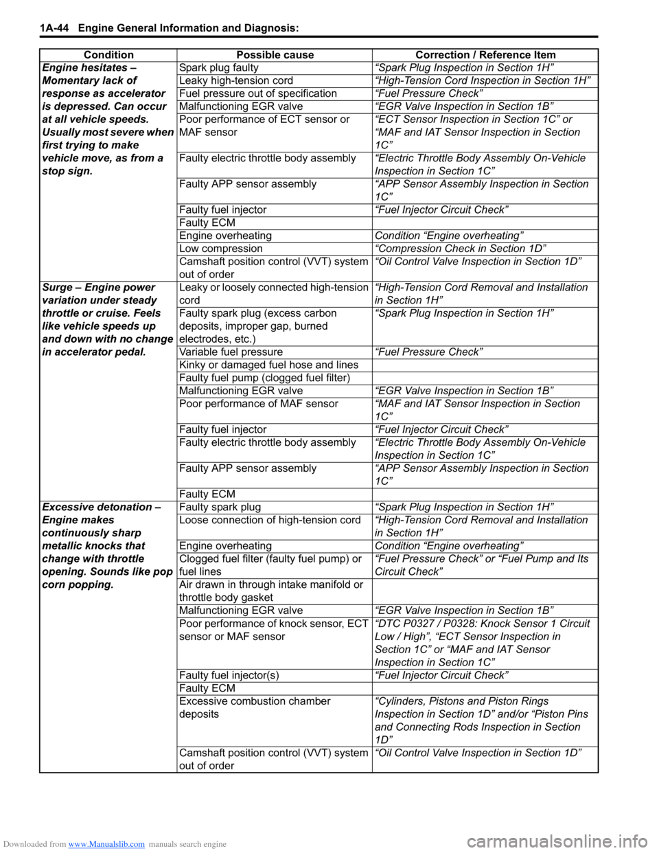
Downloaded from www.Manualslib.com manuals search engine 1A-44 Engine General Information and Diagnosis:
Engine hesitates –
Momentary lack of
response as accelerator
is depressed. Can occur
at all vehicle speeds.
Usually most severe when
first trying to make
vehicle move, as from a
stop sign.Spark plug faulty
“Spark Plug Inspection in Section 1H”
Leaky high-tension cord “High-Tension Cord Inspection in Section 1H”
Fuel pressure out of specification “Fuel Pressure Check”
Malfunctioning EGR valve “EGR Valve Inspection in Section 1B”
Poor performance of ECT sensor or
MAF sensor “ECT Sensor Inspection in Section 1C” or
“MAF and IAT Sensor Inspection in Section
1C”
Faulty electric throttle body assembly “Electric Throttle Body Assembly On-Vehicle
Inspection in Section 1C”
Faulty APP sensor assembly “APP Sensor Assembly Inspection in Section
1C”
Faulty fuel injector “Fuel Injector Circuit Check”
Faulty ECM
Engine overheating Condition “Engine overheating”
Low compression “Compression Check in Section 1D”
Camshaft position control (VVT) system
out of order “Oil Control Valve Inspection in Section 1D”
Surge – Engine power
variation under steady
throttle or cruise. Feels
like vehicle speeds up
and down with no change
in accelerator pedal. Leaky or loosely connected high-tension
cord
“High-Tension Cord Removal and Installation
in Section 1H”
Faulty spark plug (excess carbon
deposits, improper gap, burned
electrodes, etc.) “Spark Plug Inspection in Section 1H”
Variable fuel pressure “Fuel Pressure Check”
Kinky or damaged fuel hose and lines
Faulty fuel pump (clogged fuel filter)
Malfunctioning EGR valve “EGR Valve Inspection in Section 1B”
Poor performance of MAF sensor “MAF and IAT Sensor Inspection in Section
1C”
Faulty fuel injector “Fuel Injector Circuit Check”
Faulty electric throttle body assembly “Electric Throttle Body Assembly On-Vehicle
Inspection in Section 1C”
Faulty APP sensor assembly “APP Sensor Assembly Inspection in Section
1C”
Faulty ECM
Excessive detonation –
Engine makes
continuously sharp
metallic knocks that
change with throttle
opening. Sounds like pop
corn popping. Faulty spark plug
“Spark Plug Inspection in Section 1H”
Loose connection of high-tension cord “High-Tension Cord Removal and Installation
in Section 1H”
Engine overheating Condition “Engine overheating”
Clogged fuel filter (faulty fuel pump) or
fuel lines “Fuel Pressure Check” or “Fuel Pump and Its
Circuit Check”
Air drawn in through intake manifold or
throttle body gasket
Malfunctioning EGR valve “EGR Valve Inspection in Section 1B”
Poor performance of knock sensor, ECT
sensor or MAF sensor “DTC P0327 / P0328: Knock Sensor 1 Circuit
Low / High”, “ECT Sensor Inspection in
Section 1C” or “MAF and IAT Sensor
Inspection in Section 1C”
Faulty fuel injector(s) “Fuel Injector Circuit Check”
Faulty ECM
Excessive combustion chamber
deposits “Cylinders, Pistons and Piston Rings
Inspection in Section 1D” and/or “Piston Pins
and Connecting Rods In
spection in Section
1D”
Camshaft position control (VVT) system
out of order “Oil Control Valve Inspection in Section 1D”
Condition Possible cause Correction / Reference Item
Page 95 of 1496
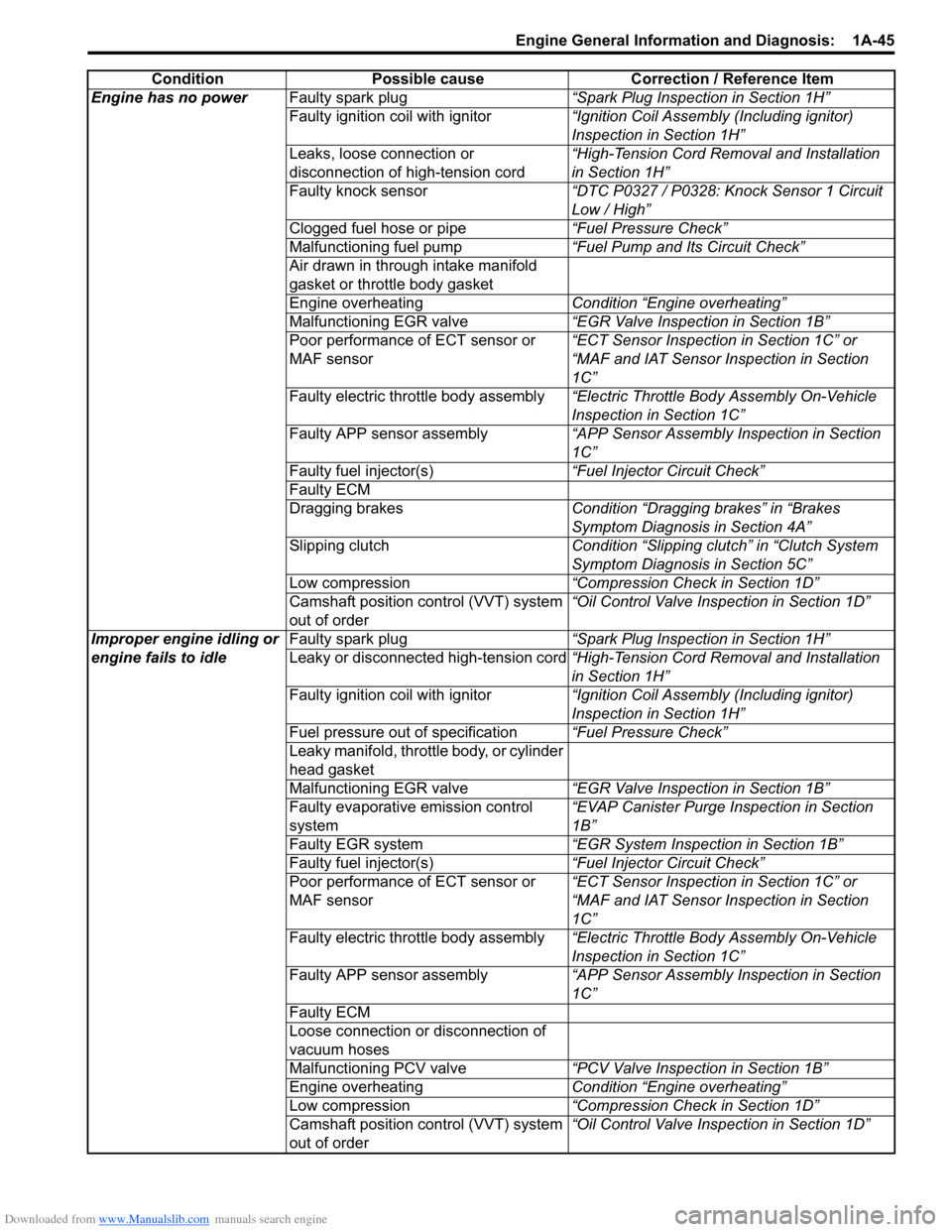
Downloaded from www.Manualslib.com manuals search engine Engine General Information and Diagnosis: 1A-45
Engine has no powerFaulty spark plug “Spark Plug Inspection in Section 1H”
Faulty ignition coil with ignitor “Ignition Coil Assembly (Including ignitor)
Inspection in Section 1H”
Leaks, loose connection or
disconnection of high-tension cord “High-Tension Cord Removal and Installation
in Section 1H”
Faulty knock sensor “DTC P0327 / P0328: Knock Sensor 1 Circuit
Low / High”
Clogged fuel hose or pipe “Fuel Pressure Check”
Malfunctioning fuel pump “Fuel Pump and Its Circuit Check”
Air drawn in through intake manifold
gasket or throttle body gasket
Engine overheating Condition “Engine overheating”
Malfunctioning EGR valve “EGR Valve Inspection in Section 1B”
Poor performance of ECT sensor or
MAF sensor “ECT Sensor Inspection in Section 1C” or
“MAF and IAT Sensor Inspection in Section
1C”
Faulty electric throttle body assembly “Electric Throttle Body Assembly On-Vehicle
Inspection in Section 1C”
Faulty APP sensor assembly “APP Sensor Assembly Inspection in Section
1C”
Faulty fuel injector(s) “Fuel Injector Circuit Check”
Faulty ECM
Dragging brakes Condition “Dragging brakes” in “Brakes
Symptom Diagnosis in Section 4A”
Slipping clutch Condition “Slipping clutch” in “Clutch System
Symptom Diagnosis in Section 5C”
Low compression “Compression Check in Section 1D”
Camshaft position control (VVT) system
out of order “Oil Control Valve Inspection in Section 1D”
Improper engine idling or
engine fails to idle Faulty spark plug
“Spark Plug Inspection in Section 1H”
Leaky or disconnected high-tension cord “High-Tension Cord Removal and Installation
in Section 1H”
Faulty ignition coil with ignitor “Ignition Coil Assembly (Including ignitor)
Inspection in Section 1H”
Fuel pressure out of specification “Fuel Pressure Check”
Leaky manifold, throttle body, or cylinder
head gasket
Malfunctioning EGR valve “EGR Valve Inspection in Section 1B”
Faulty evaporative emission control
system “EVAP Canister Purge Inspection in Section
1B”
Faulty EGR system “EGR System Inspection in Section 1B”
Faulty fuel injector(s) “Fuel Injector Circuit Check”
Poor performance of ECT sensor or
MAF sensor “ECT Sensor Inspection in Section 1C” or
“MAF and IAT Sensor Inspection in Section
1C”
Faulty electric throttle body assembly “Electric Throttle Body Assembly On-Vehicle
Inspection in Section 1C”
Faulty APP sensor assembly “APP Sensor Assembly Inspection in Section
1C”
Faulty ECM
Loose connection or disconnection of
vacuum hoses
Malfunctioning PCV valve “PCV Valve Inspection in Section 1B”
Engine overheating Condition “Engine overheating”
Low compression “Compression Check in Section 1D”
Camshaft position control (VVT) system
out of order “Oil Control Valve Inspection in Section 1D”
Condition Possible cause Correction / Reference Item
Page 155 of 1496
Downloaded from www.Manualslib.com manuals search engine Engine General Information and Diagnosis: 1A-105
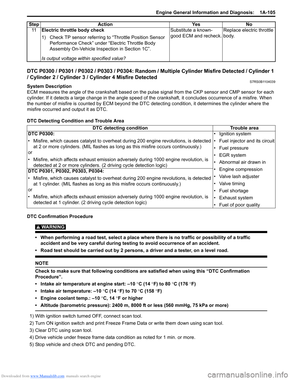
DTC P0300 / P0301 / P0302 / P0303 / P0304: Random / Multiple Cylinder Misfire Detected / Cylinder 1
/ Cylinder 2 / Cylinder 3 / Cylinder 4 Misfire Detected
S7RS0B1104039
System Description
ECM measures the angle of the crankshaft based on the pulse signal from the CKP sensor and CMP sensor for each
cylinder. If it detects a large change in the angle speed of the crankshaft, it concludes occurrence of a misfire. When
the number of misfire is counted by ECM beyond the DTC de tecting condition, it determines the cylinder where the
misfire occurred and output it as DTC.
DTC Detecting Condition and Trouble Area
DTC Confirmation Procedure
WARNING!
• When performing a road test, select a place where there is no traffic or possibility of a traffic accident and be very careful during testing to avoid occurrence of an accident.
• Road test should be carried out by 2 persons, a driver and a tester, on a level road.
NOTE
Check to make sure that following conditions ar e satisfied when using this “DTC Confirmation
Procedure”.
• Intake air temperature at engine start: –10 °C (14 ° F) to 80 °C (176 °F)
• Intake air temperature: –10 °C (14 °F) to 70 °C (158 °F)
• Engine coolant temp.: –10 °C, 14 °F or higher
• Altitude (barometric pressure): 2400 m, 8000 ft or less (560 mmHg, 75 kPa or more)
1) With ignition switch turned OFF, connect scan tool.
2) Turn ON ignition switch and print Freeze Frame Data or write them down using scan tool.
3) Clear DTC using scan tool.
4) Drive vehicle under freeze frame data condition as noted for 1 min. or more.
5) Stop vehicle and check DTC and pending DTC. 11
Electric throttle body check
1) Check TP sensor referring to “Throttle Position Sensor
Performance Check” under “Electric Throttle Body
Assembly On-Vehicle Inspection in Section 1C”.
Is output voltage within specified value? Substitute a known-
good ECM and recheck.
Replace electric throttle
body.
Step Action Yes No
DTC detecting condition
Trouble area
DTC P0300:
• Misfire, which causes catalyst to overheat during 200 engine revolutions, is detected at 2 or more cylinders. (MIL flashes as lo ng as this misfire occurs continuously.)
or
• Misfire, which affects exhaust emission adv ersely during 1000 engine revolution, is
detected at 2 or more cylinders. (2 driving cycle detection logic) • Ignition system
• Fuel injector and its circuit
• Fuel pressure
• EGR system
• Abnormal air drawn in
• Engine compression
• Valve lash adjuster
• Valve timing
• Fuel shortage
• Exhaust system
• Fuel of poor quality
DTC P0301, P0302, P0303, P0304:
• Misfire, which causes catalyst to overheat during 200 engine revolutions, is detected
at 1 cylinder. (MIL flashes as long as this misfire occurs continuously.)
or
• Misfire, which affects exhaust emission adv ersely during 1000 engine revolution, is
detected at 1 cylinder. (2 driving cycle detection logic)
Page 162 of 1496
Downloaded from www.Manualslib.com manuals search engine 1A-112 Engine General Information and Diagnosis:
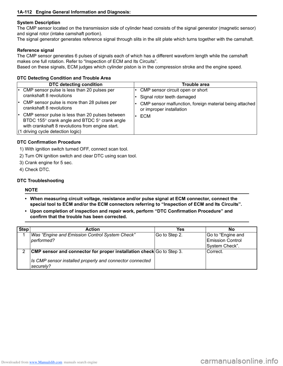
System Description
The CMP sensor located on the transmission side of cylinder head consists of the signal generator (magnetic sensor)
and signal rotor (intake camshaft portion).
The signal generator generates reference signal through slits in the slit plate which turns together with the camshaft.
Reference signal
The CMP sensor generates 6 pulses of si gnals each of which has a different waveform length while the camshaft
makes one full rotation. Refer to “Inspection of ECM and Its Circuits”.
Based on these signals, ECM judges which cylinder pist on is in the compression stroke and the engine speed.
DTC Detecting Condition and Trouble Area
DTC Confirmation Procedure 1) With ignition switch turned OFF, connect scan tool.
2) Turn ON ignition switch and clear DTC using scan tool.
3) Crank engine for 5 sec.
4) Check DTC.
DTC Troubleshooting
NOTE
• When measuring circuit voltage, resistance and/ or pulse signal at ECM connector, connect the
special tool to ECM and/or the ECM connectors re ferring to “Inspection of ECM and Its Circuits”.
• Upon completion of inspection and repair work, perform “DTC Confirmation Procedure” and confirm that the trouble has been corrected.
DTC detecting condition Trouble area
• CMP sensor pulse is less than 20 pulses per crankshaft 8 revolutions
• CMP sensor pulse is more than 28 pulses per crankshaft 8 revolutions
• CMP sensor pulse is less than 20 pulses between BTDC 155 ° crank angle and BTDC 5 ° crank angle
with crankshaft 8 revolutions from engine start.
(1 driving cycle detection logic) • CMP sensor circuit open or short
• Signal rotor teeth damaged
• CMP sensor malfunction, foreign material being attached
or improper installation
•ECM
Step Action YesNo
1 Was “Engine and Emission Control System Check”
performed? Go to Step 2.
Go to “Engine and
Emission Control
System Check”.
2 CMP sensor and connector for proper installation check
Is CMP sensor installed properly and connector connected
securely? Go to Step 3.
Correct.
Page 289 of 1496
Downloaded from www.Manualslib.com manuals search engine Engine Mechanical: 1D-4
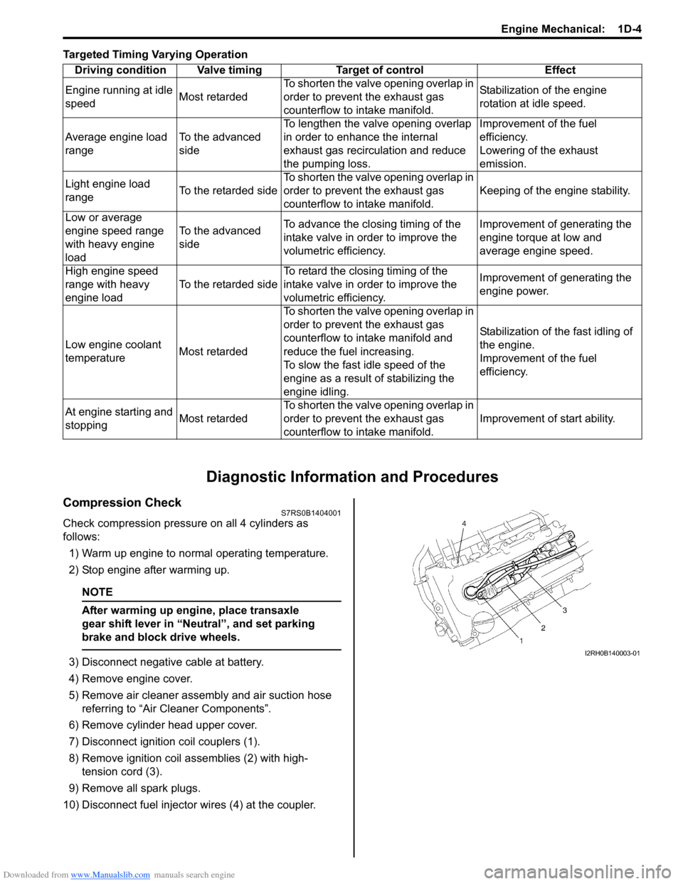
Targeted Timing Varying Operation
Diagnostic Information and Procedures
Compression CheckS7RS0B1404001
Check compression pressure on all 4 cylinders as
follows:
1) Warm up engine to normal operating temperature.
2) Stop engine after warming up.
NOTE
After warming up engine, place transaxle
gear shift lever in “Neutral”, and set parking
brake and block drive wheels.
3) Disconnect negative cable at battery.
4) Remove engine cover.
5) Remove air cleaner assembly and air suction hose referring to “Air Cleaner Components”.
6) Remove cylinder head upper cover.
7) Disconnect ignition coil couplers (1).
8) Remove ignition coil assemblies (2) with high- tension cord (3).
9) Remove all spark plugs.
10) Disconnect fuel injector wires (4) at the coupler. Driving condition Valve timing Target of control Effect
Engine running at idle
speed Most retardedTo shorten the valve opening overlap in
order to prevent the exhaust gas
counterflow to in
take manifold. Stabilization of the engine
rotation at idle speed.
Average engine load
range To the advanced
sideTo lengthen the valve opening overlap
in order to enhance the internal
exhaust gas recirculation and reduce
the pumping loss. Improvement of the fuel
efficiency.
Lowering of the exhaust
emission.
Light engine load
range To the retarded sideTo shorten the valve opening overlap in
order to prevent the exhaust gas
counterflow to in
take manifold. Keeping of the engine stability.
Low or average
engine speed range
with heavy engine
load To the advanced
side
To advance the closing timing of the
intake valve in order to improve the
volumetric efficiency. Improvement of generating the
engine torque at low and
average engine speed.
High engine speed
range with heavy
engine load To the retarded sideTo retard the closing timing of the
intake valve in order to improve the
volumetric efficiency. Improvement of generating the
engine power.
Low engine coolant
temperature Most retardedTo shorten the valve opening overlap in
order to prevent the exhaust gas
counterflow to intake manifold and
reduce the fuel increasing.
To slow the fast idle speed of the
engine as a result of stabilizing the
engine idling. Stabilization of the fast idling of
the engine.
Improvement of the fuel
efficiency.
At engine starting and
stopping Most retardedTo shorten the valve opening overlap in
order to prevent the exhaust gas
counterflow to in
take manifold. Improvement of start ability.I2RH0B140003-01
Page 290 of 1496
Downloaded from www.Manualslib.com manuals search engine 1D-5 Engine Mechanical:
11) Connect negative cable at battery.
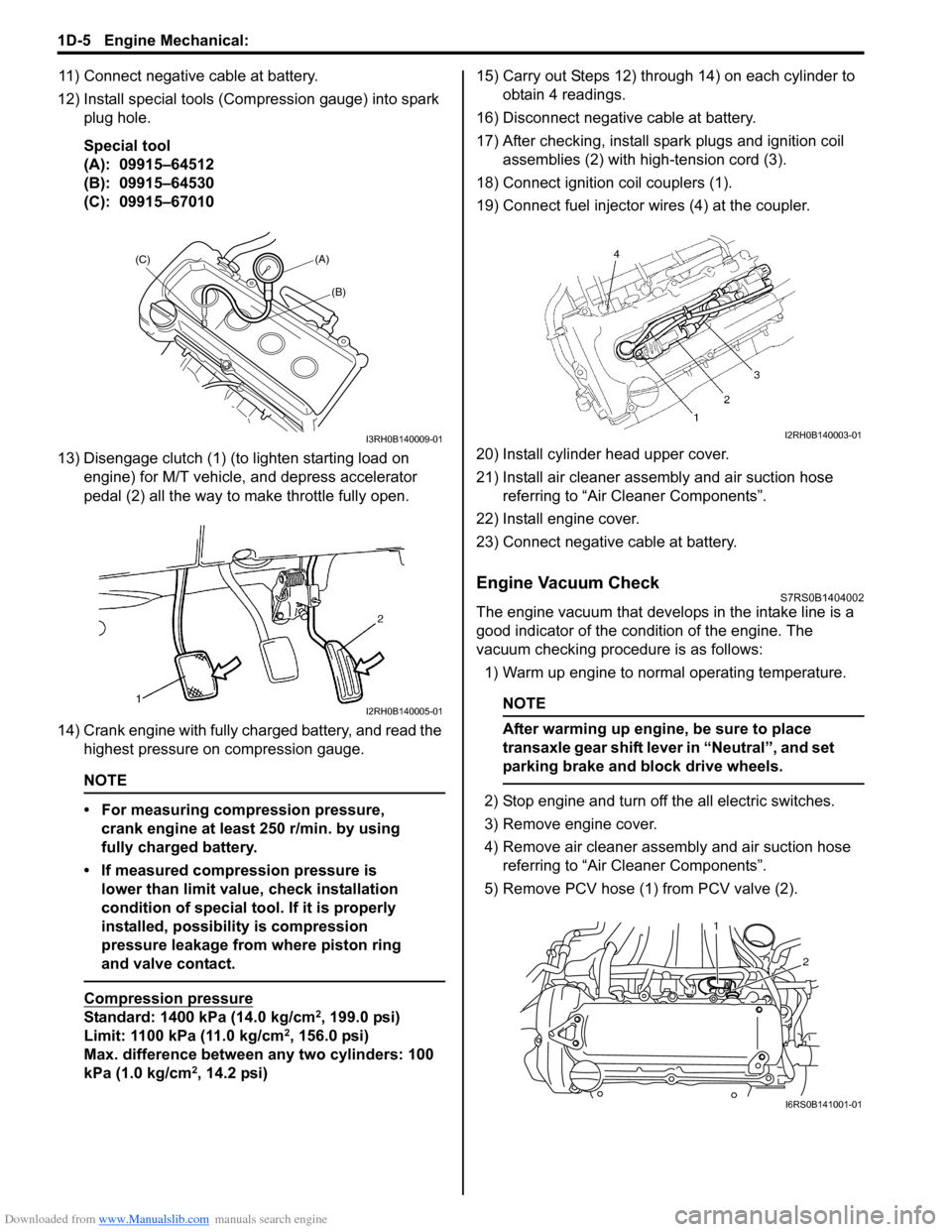
12) Install special tools (Compression gauge) into spark plug hole.
Special tool
(A): 09915–64512
(B): 09915–64530
(C): 09915–67010
13) Disengage clutch (1) (to lighten starting load on engine) for M/T vehicle, and depress accelerator
pedal (2) all the way to make throttle fully open.
14) Crank engine with fully charged battery, and read the highest pressure on compression gauge.
NOTE
• For measuring compression pressure, crank engine at least 250 r/min. by using
fully charged battery.
• If measured compression pressure is lower than limit value, check installation
condition of special tool. If it is properly
installed, possibility is compression
pressure leakage from where piston ring
and valve contact.
Compression pressure
Standard: 1400 kPa (14.0 kg/cm2, 199.0 psi)
Limit: 1100 kPa (11.0 kg/cm2, 156.0 psi)
Max. difference between any two cylinders: 100
kPa (1.0 kg/cm
2, 14.2 psi) 15) Carry out Steps 12) through 14) on each cylinder to
obtain 4 readings.
16) Disconnect negative cable at battery.
17) After checking, install spark plugs and ignition coil assemblies (2) with high-tension cord (3).
18) Connect ignition coil couplers (1).
19) Connect fuel injector wires (4) at the coupler.
20) Install cylinder head upper cover.
21) Install air cleaner assembly and air suction hose referring to “Air Cleaner Components”.
22) Install engine cover.
23) Connect negative cable at battery.
Engine Vacuum CheckS7RS0B1404002
The engine vacuum that develops in the intake line is a
good indicator of the condition of the engine. The
vacuum checking procedure is as follows:
1) Warm up engine to normal operating temperature.
NOTE
After warming up engine, be sure to place
transaxle gear shift lever in “Neutral”, and set
parking brake and block drive wheels.
2) Stop engine and turn off the all electric switches.
3) Remove engine cover.
4) Remove air cleaner assembly and air suction hose referring to “Air Cleaner Components”.
5) Remove PCV hose (1) from PCV valve (2).
(A)
(C)
(B)
I3RH0B140009-01
I2RH0B140005-01
I2RH0B140003-01
2
1
I6RS0B141001-01
Page 331 of 1496
Downloaded from www.Manualslib.com manuals search engine Engine Mechanical: 1D-46
Pistons, Piston Rings, Connecting Rods and
Cylinders Disassembly and Assembly
S7RS0B1406031
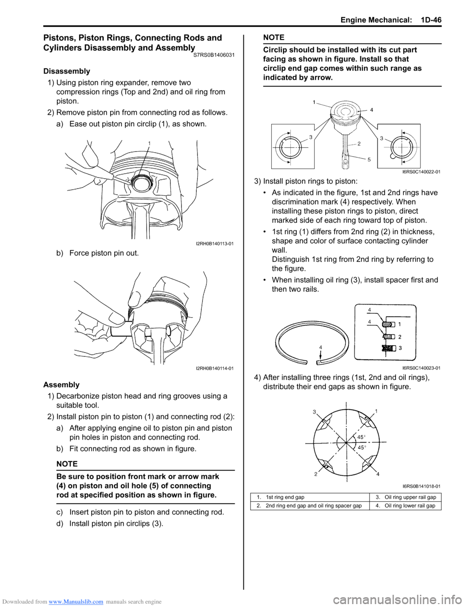
Disassembly1) Using piston ring expander, remove two compression rings (Top and 2nd) and oil ring from
piston.
2) Remove piston pin from connecting rod as follows. a) Ease out piston pin circlip (1), as shown.
b) Force piston pin out.
Assembly 1) Decarbonize piston head and ring grooves using a suitable tool.
2) Install piston pin to piston (1) and connecting rod (2): a) After applying engine oil to piston pin and piston pin holes in piston and connecting rod.
b) Fit connecting rod as shown in figure.
NOTE
Be sure to position front mark or arrow mark
(4) on piston and oil hole (5) of connecting
rod at specified position as shown in figure.
c) Insert piston pin to piston and connecting rod.
d) Install piston pin circlips (3).
NOTE
Circlip should be installed with its cut part
facing as shown in figure. Install so that
circlip end gap comes within such range as
indicated by arrow.
3) Install piston rings to piston:
• As indicated in the figure, 1st and 2nd rings have discrimination mark (4) respectively. When
installing these piston rings to piston, direct
marked side of each ring toward top of piston.
• 1st ring (1) differs from 2nd ring (2) in thickness, shape and color of surface contacting cylinder
wall.
Distinguish 1st ring from 2nd ring by referring to
the figure.
• When installing oil ring (3), install spacer first and then two rails.
4) After installing three rings (1st, 2nd and oil rings), distribute their end gaps as shown in figure.
I2RH0B140113-01
I2RH0B140114-01
1. 1st ring end gap 3. Oil ring upper rail gap
2. 2nd ring end gap and oil ring spacer gap 4. Oil ring lower rail gap
I6RS0C140022-01
I6RS0C140023-01
I6RS0B141018-01