Door speaker SUZUKI SWIFT 2008 2.G Service Workshop Manual
[x] Cancel search | Manufacturer: SUZUKI, Model Year: 2008, Model line: SWIFT, Model: SUZUKI SWIFT 2008 2.GPages: 1496, PDF Size: 34.44 MB
Page 1169 of 1496

Downloaded from www.Manualslib.com manuals search engine Table of Contents 9-iii
Door Switch (Front / Rear Door) Inspection ...... 9C-17
Rear End Door Switch Inspection ..................... 9C-17
Outside Air Temperature Sensor Removal and Installation (If Equipped) .......................... 9C-17
Outside Air Temperature Sensor Inspection (If Equipped) ................................................... 9C-17
Instrument Panel Removal and Installation....... 9C-18
Information Display (Clock) Removal and Installation ....................................................... 9C-19
Audio Unit Removal and In stallation ................. 9C-19
Front Speaker Removal and Installation ........... 9C-19
Rear Speaker Removal and Installation............ 9C-20
Horn Removal and Installation .......................... 9C-20
Horn Inspection ................................................. 9C-20
Horn Relay Inspection ....................................... 9C-20
Antenna Amplifier Removal and Installation ..... 9C-21
Remote Audio Control Switch Removal and Installation (If Equipped) ................................. 9C-21
Remote Audio Control Switch Inspection (If Equipped)........................................................ 9C-22
Vehicle Speed Signal Inspection (For Audio Unit) (If Equipped) ........................................... 9C-22
Specifications ..................................................... 9C-22
Tightening Torque Specifications ...................... 9C-22
Wipers / Washers............ ......................... 9D-1
Diagnostic Information and Procedures ............ 9D-1
Front Wiper and Washer Symptom Diagnosis .... 9D-1
Rear Wiper and Washer Symptom Diagnosis..... 9D-1
Repair Instructions .............................................. 9D-2 Wipers and Washers Components ..................... 9D-2
Washer Tank and Washer Pump Removal and Installation .................................................. 9D-3
Washer Pump Inspection .................................... 9D-3
Windshield Wiper Removal and Installation ........ 9D-4
Windshield Wiper Motor Inspection..................... 9D-5
Rear Wiper Removal and Installation.................. 9D-6
Rear Wiper Motor Inspection .............................. 9D-7
Windshield Wiper and Washer Switch Removal and Installation................................... 9D-7
Windshield Wiper and Washer Switch Inspection.......................................................... 9D-8
Rear Wiper and Washer Switch Removal and Installation ......................................................... 9D-9
Rear Wiper and Washer Switch Inspection......... 9D-9
Rear Wiper Relay Removal and Installation ..... 9D-10
Rear Wiper Relay Inspection ............................ 9D-10
Specifications ..................................................... 9D-10
Tightening Torque Specifications ...................... 9D-10
Glass / Windows / Mirrors.. ..................... 9E-1
General Description ............................................. 9E-1
Rear End Door Window Defogger System Description ........................................................ 9E-1
Windshield Construction ..................................... 9E-1
Diagnostic Information and Procedures ............ 9E-2 Rear End door Window Defogger Symptom Diagnosis .......................................................... 9E-2 Power Window Control System Symptom
Diagnosis .......................................................... 9E-2
Power Door Mirror Control System Symptom Diagnosis .......................................................... 9E-3
Door Mirror Heater Symptom Diagnosis (If
Equipped) .......................................................... 9E-3
Repair Instructions ........... ................................... 9E-4
Windshield Removal and In stallation .................. 9E-4
Front Door Window Components ........................ 9E-8
Front Door Glass Removal and Installation ........ 9E-8
Front Door Window Re gulator Removal and
Installation ......................................................... 9E-9
Front Door Window Regula tor Inspection ......... 9E-10
Rear Door Window Components ...................... 9E-10
Rear Door Glass Removal and Installation ....... 9E-11
Rear Door Window Regulator Removal and Installation ....................................................... 9E-12
Rear Door Window Regulato r Inspection .......... 9E-12
Rear End Door Window Components ............... 9E-13
Rear End Door Glass Removal and Installation ....................................................... 9E-13
Rear End Door Window Defogger Switch Inspection ........................................................ 9E-14
Rear End Door Window Defogger Relay Inspection ........................................................ 9E-14
Rear End Door Window Defogger Wire Inspection ........................................................ 9E-15
Rear End Door Window Defogger Wire
Repair.............................................................. 9E-15
Power Window Main Switch Inspection ............ 9E-16
Power Window Sub Switch Inspection .............. 9E-17
Door Mirror Components.. ................................. 9E-18
Door Mirror Removal and In stallation................ 9E-18
Power Door Mirror Switch Inspection ................ 9E-18
Power Door Mirror Actuator Inspection ............. 9E-19
Door Mirror Heater Switch Inspection (If Equipped) ........................................................ 9E-19
Door Mirror Heater Inspec tion (If Equipped) ..... 9E-19
Special Tools and Equipmen t ........................... 9E-19
Recommended Service Material ....................... 9E-19
Security and Locks......... ..........................9F-1
General Description ............................................. 9F-1
Key Coding Construction .................................... 9F-1
Rear End Door Opener System Description ....... 9F-1
Component Location ............ ............................... 9F-2
Power Door Lock and Keyless Entry System
Component Location ......................................... 9F-2
Diagnostic Information and Procedures ............ 9F-3 Power Door Lock System Symptom Diagnosis .......................................................... 9F-3
Power Door Lock System Operation Inspection .......................................................... 9F-3
Keyless Entry System Symptom Diagnosis (If
Equipped) .......................................................... 9F-4
Keyless Entry System Operation Inspection ....... 9F-5
Door Lock Function of Keyless Start System Symptom Diagnosis (If Equipped)..................... 9F-5
Page 1175 of 1496
![SUZUKI SWIFT 2008 2.G Service Workshop Manual Downloaded from www.Manualslib.com manuals search engine Wiring Systems: 9A-4
How to Read Connector Layout DiagramS7RS0B9101004
[A-1]: Harness symbol and corresponding harness name
A: Battery harness SUZUKI SWIFT 2008 2.G Service Workshop Manual Downloaded from www.Manualslib.com manuals search engine Wiring Systems: 9A-4
How to Read Connector Layout DiagramS7RS0B9101004
[A-1]: Harness symbol and corresponding harness name
A: Battery harness](/img/20/7607/w960_7607-1174.png)
Downloaded from www.Manualslib.com manuals search engine Wiring Systems: 9A-4
How to Read Connector Layout DiagramS7RS0B9101004
[A-1]: Harness symbol and corresponding harness name
A: Battery harness
B: A/C harness
C: Engine harness
D: Injector harness
E: Main harness, Oil pressure switch wire, Console wire
G: Instrument panel harness
J: Side door wire (Power window)
K: Interior light harness, Rear speaker wire, Roof wire
L: Floor harness, G sensor wire (Fuel pump harness)
M: Rear bumper harness
O: Rear end door harness
Q: Air bag/Pretensioner harness
R: (Fuel pump wire)
[A-2]: Connector Number
[B]: Ground point No.
12
11
[B] [B]
Connector code
[A-1] [A-2]L 36
L13 L15
R01
L14
L12
L11L10
L09 L36
R02
L24
L25
L33
L28
L20 L26 (TO O01)
{
L05
L16
L32
L19
L01 (TO G01)
L02 (TO E04)
L03 (TO E05)
L42
R05
R04
L07 (TO K02)
I2RH01910901-01
Page 1192 of 1496
Downloaded from www.Manualslib.com manuals search engine 9A-21 Wiring Systems:
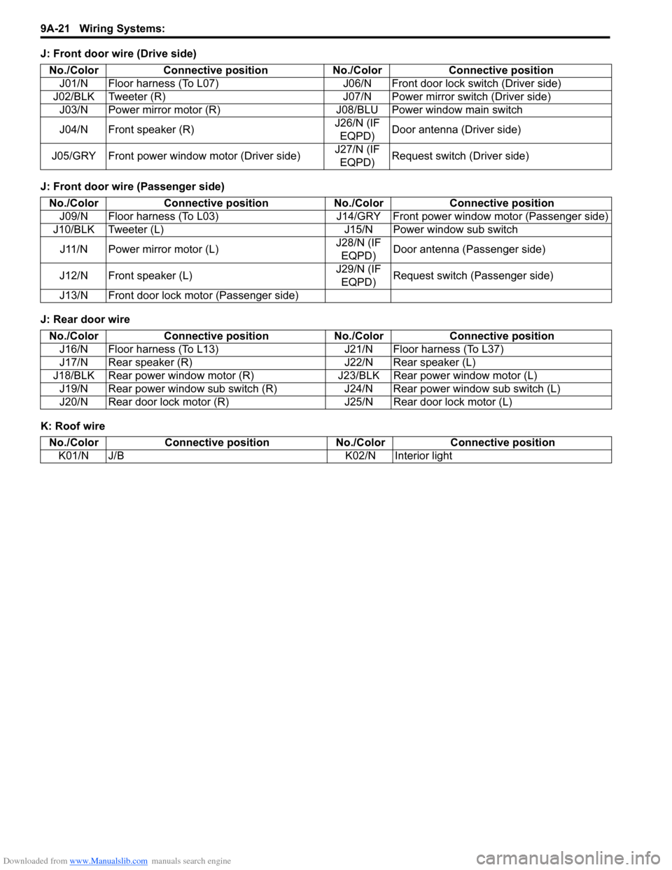
J: Front door wire (Drive side)
J: Front door wire (Passenger side)
J: Rear door wire
K: Roof wireNo./Color Connective position No.
/Color Connective position
J01/N Floor harness (To L07) J06/N Front door lock switch (Driver side)
J02/BLK Tweeter (R) J07/N Power mirror switch (Driver side) J03/N Power mirror motor (R) J08/BLU Power window main switch
J04/N Front speaker (R) J26/N (IF
EQPD) Door antenna (Driver side)
J05/GRY Front power window motor (Driver side) J27/N (IF
EQPD) Request switch (Driver side)
No./Color
Connective position No./ColorConnective position
J09/N Floor harness (To L03) J14/GRY Front power window motor (Passenger side)
J10/BLK Tweeter (L) J15/N Power window sub switch
J11/N Power mirror motor (L) J28/N (IF
EQPD) Door antenna (Passenger side)
J12/N Front speaker (L) J29/N (IF
EQPD) Request switch (Passenger side)
J13/N Front door lock motor (Passenger side)
No./Color Connective position No./ColorConnective position
J16/N Floor harness (To L13) J21/N Floor harness (To L37)
J17/N Rear speaker (R) J22/N Rear speaker (L)
J18/BLK Rear power window motor (R) J23/BLK Rear power window motor (L)
J19/N Rear power window sub switch (R) J24/N Rear power window sub switch (L)
J20/N Rear door lock motor (R) J25/N Rear door lock motor (L)
No./ColorConnective position No./Color Connective position
K01/N J/B K02/N Interior light
Page 1193 of 1496
Downloaded from www.Manualslib.com manuals search engine Wiring Systems: 9A-22
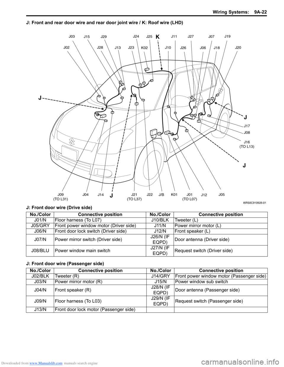
J: Front and rear door wire and rear door joint wire / K: Roof wire (LHD)
J: Front door wire (Drive side)
J: Front door wire (Passenger side)
J04J21
(TO L37)
J02
J03
J13
J15J29
J28 J25J23
J24
JJ09
(TO L31) J22J01
(TO L07)J12
J10J06J18
J19
J20
J J
J17
J08
J16
(TO L13)
J05
J11
J26
J07
J27
J14
J
K02
K
J/BK01
I6RS0C910928-01
No./Color Connective position No./Color Connective position
J01/N Floor harness (To L07) J10/BLK Tweeter (L)
J05/GRY Front power window motor (Driver side) J11/N Power mirror motor (L) J06/N Front door lock switch (Dri ver side)J12/N Front speaker (L)
J07/N Power mirror switch (Driver side) J26/N (IF
EQPD) Door antenna (Driver side)
J08/BLU Power window main switch J27/N (IF
EQPD) Request switch (Driver side)
No./Color
Connective position No./ColorConnective position
J02/BLK Tweeter (R) J14/GRY Front power window motor (Passenger side)
J03/N Power mirror motor (R) J15/N Power window sub switch
J04/N Front speaker (R) J28/N (IF
EQPD) Door antenna (Passenger side)
J09/N Floor harness (To L03) J29/N (IF
EQPD) Request switch (Passenger side)
J13/N Front door lock motor (Passenger side)
Page 1194 of 1496
Downloaded from www.Manualslib.com manuals search engine 9A-23 Wiring Systems:
J: Rear door wire
K: Roof wire
FloorS7RS0B910A005
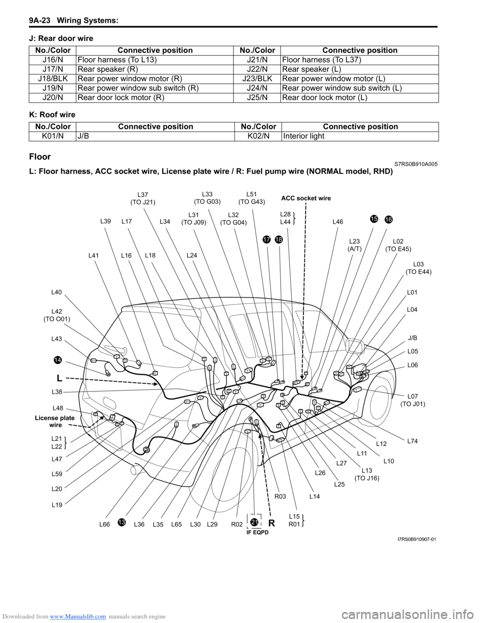
L: Floor harness, ACC socket wire, License plate wire / R: Fuel pum p wire (NORMAL model, RHD)
No./Color
Connective position No./ColorConnective position
J16/N Floor harness (To L13) J21/N Floor harness (To L37)
J17/N Rear speaker (R) J22/N Rear speaker (L)
J18/BLK Rear power window motor (R) J23/BLK Rear power window motor (L)
J19/N Rear power window sub switch (R) J24/N Rear power window sub switch (L)
J20/N Rear door lock motor (R) J25/N Rear door lock motor (L)
No./ColorConnective position No./Color Connective position
K01/N J/B K02/N Interior light
21
L48
14
L43
L42
(TO O01)
L40
L41
L33
(TO G03)
L32
(TO G04)
L46
ACC socket wire
L02
(TO E45)
L03
(TO E44)
L01
L04
L05
L06
L07
(TO J01)
L74
1516
L23
(A/T)1718
L31
(TO J09)
L24
13
L20L19
R02L65L66 L15
R01
L12
L10
L11
L13
(TO J16)
L14
R03 L26
L25
L27
L30L29
L17
L18 L51
(TO G43)
L36 L35
L37
(TO J21)
L34
L38
L16 L28
L44
L
L39
J/B
R
L47
L59
L21
L22
License plate
wire
IF EQPDI7RS0B910907-01
Page 1314 of 1496
Downloaded from www.Manualslib.com manuals search engine 9C-19 Instrumentation / Driver Info. / Horn:
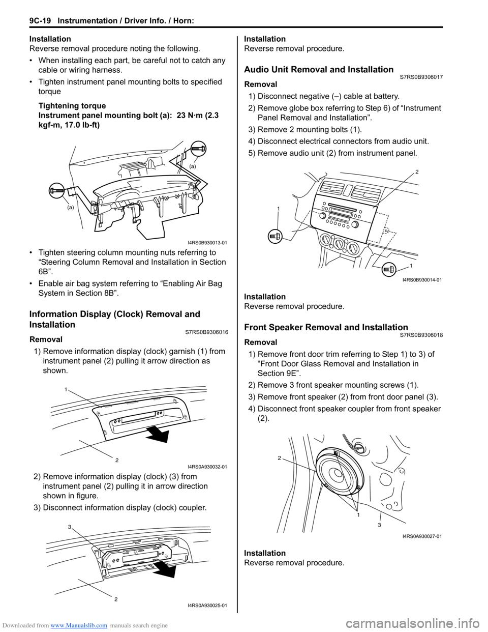
Installation
Reverse removal procedure noting the following.
• When installing each part, be careful not to catch any
cable or wiring harness.
• Tighten instrument panel mounting bolts to specified
torque
Tightening torque
Instrument panel mounting bolt (a): 23 N·m (2.3
kgf-m, 17.0 lb-ft)
• Tighten steering column mounting nuts referring to “Steering Column Removal an d Installation in Section
6B”.
• Enable air bag system referring to “Enabling Air Bag System in Section 8B”.
Information Display (Clock) Removal and
Installation
S7RS0B9306016
Removal
1) Remove information display (clock) garnish (1) from instrument panel (2) pulling it arrow direction as
shown.
2) Remove information di splay (clock) (3) from
instrument panel (2) pulli ng it in arrow direction
shown in figure.
3) Disconnect information display (clock) coupler. Installation
Reverse removal procedure.
Audio Unit Removal and InstallationS7RS0B9306017
Removal
1) Disconnect negative (–) cable at battery.
2) Remove globe box referring to Step 6) of “Instrument Panel Removal and Installation”.
3) Remove 2 mounting bolts (1).
4) Disconnect electrical connectors from audio unit.
5) Remove audio unit (2) from instrument panel.
Installation
Reverse removal procedure.
Front Speaker Removal and InstallationS7RS0B9306018
Removal 1) Remove front door trim refe rring to Step 1) to 3) of
“Front Door Glass Remo val and Installation in
Section 9E”.
2) Remove 3 front speaker mounting screws (1).
3) Remove front speaker (2) from front door panel (3).
4) Disconnect front speaker coupler from front speaker (2).
Installation
Reverse removal procedure.
(a) (a)
I4RS0B930013-01
1
2I4RS0A930032-01
3
2I4RS0A930025-01
2
1
1
I4RS0B930014-01
1
2
3
I4RS0A930027-01
Page 1315 of 1496
Downloaded from www.Manualslib.com manuals search engine Instrumentation / Driver Info. / Horn: 9C-20
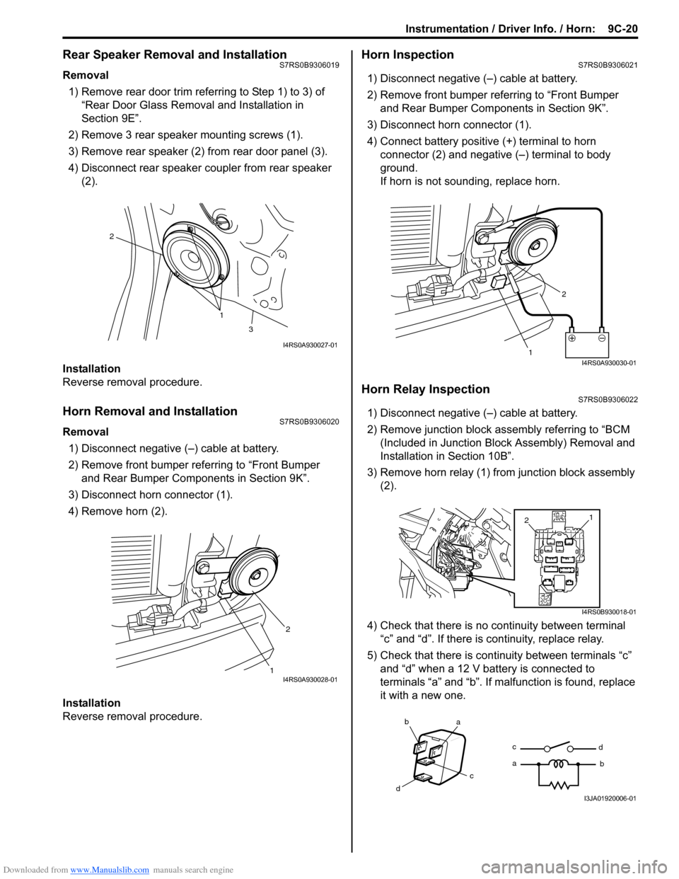
Rear Speaker Removal and InstallationS7RS0B9306019
Removal
1) Remove rear door trim referring to Step 1) to 3) of “Rear Door Glass Removal and Installation in
Section 9E”.
2) Remove 3 rear speaker mounting screws (1).
3) Remove rear speaker (2) from rear door panel (3).
4) Disconnect rear speaker coupler from rear speaker (2).
Installation
Reverse removal procedure.
Horn Removal and InstallationS7RS0B9306020
Removal 1) Disconnect negative (–) cable at battery.
2) Remove front bumper referring to “Front Bumper and Rear Bumper Components in Section 9K”.
3) Disconnect horn connector (1).
4) Remove horn (2).
Installation
Reverse removal procedure.
Horn InspectionS7RS0B9306021
1) Disconnect negative (–) cable at battery.
2) Remove front bumper referring to “Front Bumper and Rear Bumper Components in Section 9K”.
3) Disconnect horn connector (1).
4) Connect battery positive (+) terminal to horn
connector (2) and negative (–) terminal to body
ground.
If horn is not sounding, replace horn.
Horn Relay InspectionS7RS0B9306022
1) Disconnect negative (–) cable at battery.
2) Remove junction block assembly referring to “BCM (Included in Junction Bl ock Assembly) Removal and
Installation in Section 10B”.
3) Remove horn relay (1) from junction block assembly (2).
4) Check that there is no continuity between terminal “c” and “d”. If there is continuity, replace relay.
5) Check that there is continuity between terminals “c” and “d” when a 12 V battery is connected to
terminals “a” and “b”. If malfunction is found, replace
it with a new one.
1
2
3
I4RS0A930027-01
12I4RS0A930028-01
1 2I4RS0A930030-01
1
2
I4RS0B930018-01
ba
c
d c
a
d
bI3JA01920006-01