Radiator removal and installation SUZUKI SWIFT 2008 2.G Service Workshop Manual
[x] Cancel search | Manufacturer: SUZUKI, Model Year: 2008, Model line: SWIFT, Model: SUZUKI SWIFT 2008 2.GPages: 1496, PDF Size: 34.44 MB
Page 48 of 1496

Downloaded from www.Manualslib.com manuals search engine 1-iv Table of Contents
Engine Lubrication System.....................1E-1
General Description ............................................. 1E-1
Engine Lubrication Description ........................... 1E-1
Diagnostic Information and Procedures ............ 1E-2 Oil Pressure Check ............................................. 1E-2
Repair Instructions ........... ................................... 1E-3
Heat Exchanger Components ............................. 1E-3
Heat Exchanger On-Vehicle Inspection .............. 1E-4
Heat Exchanger Removal and Installation .......... 1E-4
Oil Pan and Oil Pump Strainer Components....... 1E-5
Oil Pan and Oil Pump Strainer Removal and
Installation ......................................................... 1E-5
Oil Pan and Oil Pump Stra iner Cleaning ............. 1E-7
Oil Pump Components ........................................ 1E-8
Oil Pump Removal and Installation ..................... 1E-8
Oil Pump Disassembly and Reassembly ............ 1E-8
Oil Pump Inspection ............................................ 1E-9
Specifications .... ................................................. 1E-11
Tightening Torque Specifications ...................... 1E-11
Special Tools and Equipmen t ........................... 1E-11
Recommended Service Material ....................... 1E-11
Special Tool ...................................................... 1E-11
Engine Cooling System ..... ...................... 1F-1
General Description .......... ................................... 1F-1
Cooling System Descriptio n ................................ 1F-1
Coolant Description ............................................. 1F-1
Schematic and Routing Diagram ........................ 1F-2 Coolant Circulation .............................................. 1F-2
Diagnostic Information and Procedures ............ 1F-4 Engine Cooling Symptom Diagnosis ................... 1F-4
Repair Instructions ........... ................................... 1F-5
Cooling System Components.............................. 1F-5
Coolant Level Check ........................................... 1F-6
Engine Cooling System Inspection and Cleaning ............................................................ 1F-6
Cooling System Draining.. ................................... 1F-6
Cooling System Flush and Refill ......................... 1F-7
Cooling Water Pipes or Hoses Removal and Installation ......................................................... 1F-7
Thermostat Removal and In stallation.................. 1F-8
Thermostat Inspection......................................... 1F-8
Radiator Cooling Fan Motor On-Vehicle Inspection .......................................................... 1F-9
Radiator Cooling Fan Rela y Inspection............... 1F-9
Radiator Cooling Fan Removal and Installation ....................................................... 1F-10
Radiator On-Vehicle Inspection and Cleaning .. 1F-10
Radiator Removal and Inst allation .................... 1F-10
Water Pump Removal and In stallation .............. 1F-11
Water Pump Inspection ..................................... 1F-11
Specifications .... ................................................. 1F-12
Tightening Torque Specifications ...................... 1F-12
Special Tools and Equipmen t ........................... 1F-12
Recommended Service Material ....................... 1F-12
Fuel System ................... .......................... 1G-1
Precautions.......................................................... 1G-1 Precautions on Fuel System Service ................. 1G-1
General Description ............................................ 1G-1 Fuel System Description .................................... 1G-1
Fuel Delivery System Description ...................... 1G-1
Fuel Pump Description ....................................... 1G-2
Schematic and Routing Diagram ....................... 1G-2 Fuel Delivery System Diag ram........................... 1G-2
Diagnostic Information and Procedures ........... 1G-2 Fuel Pressure Inspection ................................... 1G-2
Fuel Cut Operation Inspection ........................... 1G-3
Repair Instructions ............ ................................. 1G-4
Fuel System Components .................................. 1G-4
Fuel Hose Disconnecting and Reconnecting ..... 1G-5
Fuel Pressure Relief Procedure ......................... 1G-7
Fuel Leakage Check Procedure......................... 1G-7
Fuel Lines On-Vehicle Inspection ...................... 1G-7
Fuel Pipe Removal and Installation.................... 1G-7
Fuel Injector On-Vehicle Inspection ................... 1G-8
Fuel Injector Removal and Installation ............... 1G-8
Fuel Injector Inspection ...................................... 1G-9
Fuel Filler Cap Inspection . ............................... 1G-10
Fuel Tank Inlet Valve Removal and Installation ...................................................... 1G-11
Fuel Tank Inlet Valve Inspection ...................... 1G-12
Fuel Tank Removal and Installation ................. 1G-12
Fuel Tank Inspection ........................................ 1G-13
Fuel Tank Purging Procedure .......................... 1G-14
Fuel Pump On-Vehicle Inspection.................... 1G-14
Fuel Pump Assembly Removal and Installation ...................................................... 1G-14
Main Fuel Level Sensor Removal and Installation ...................................................... 1G-15
Fuel Pump Inspection ...................................... 1G-16
Specifications ..................... ............................... 1G-16
Tightening Torque Specifications ..................... 1G-16
Special Tools and Equipmen t .......................... 1G-17
Special Tool ..................................................... 1G-17
Ignition System .............. .......................... 1H-1
General Description .............................................1H-1
Ignition System Construction ..............................1H-1
Schematic and Routing Diagram ........................1H-2 Ignition System Wiring Circuit Diagram...............1H-2
Component Location ............ ...............................1H-3
Ignition System Components Location................1H-3
Diagnostic Information and Procedures ............1H-4 Ignition System Symptom Diagnosis...................1H-4
Reference Waveform of Ignition System.............1H-4
Ignition System Check ........................................1H-4
Ignition Spark Test ..............................................1H-6
Repair Instructions ............ ..................................1H-6
High-Tension Cord Removal and Installation......1H-6
High-Tension Cord Inspection.............................1H-7
Spark Plug Removal and Installation ..................1H-7
Spark Plug Inspection .........................................1H-7
Ignition Coil Assembly (Including ignitor)
Removal and Installation ...................................1H-8
Ignition Coil Assembly (Including ignitor)
Inspection ..........................................................1H-8
Page 92 of 1496
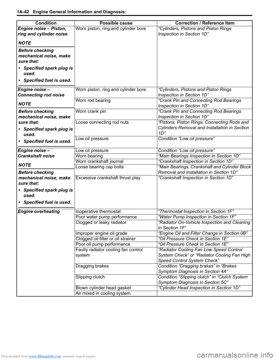
Downloaded from www.Manualslib.com manuals search engine 1A-42 Engine General Information and Diagnosis:
Engine noise – Piston,
ring and cylinder noise
NOTE
Before checking
mechanical noise, make
sure that:
• Specified spark plug is used.
• Specified fuel is used.
Worn piston, ring and cylinder bore “Cylinders, Pistons and Piston Rings
Inspection in Section 1D”
Engine noise –
Connecting rod noise
NOTE
Before checking
mechanical noise, make
sure that:
• Specified spark plug is used.
• Specified fuel is used.
Worn piston, ring and cylinder bore “Cylinders, Pistons and Piston Rings
Inspection in Section 1D”
Worn rod bearing “Crank Pin and Connecting Rod Bearings
Inspection in Section 1D”
Worn crank pin “Crank Pin and Connecting Rod Bearings
Inspection in Section 1D”
Loose connecting rod nuts “Pistons, Piston Rings, Connecting Rods and
Cylinders Removal and Installation in Section
1D”
Low oil pressure Condition “Low oil pressure”
Engine noise –
Crankshaft noise
NOTE
Before checking
mechanical noise, make
sure that:
• Specified spark plug is used.
• Specified fuel is used.
Low oil pressure Condition “Low oil pressure”
Worn bearing “Main Bearings Inspection in Section 1D”
Worn crankshaft journal “Crankshaft Inspection in Section 1D”
Loose bearing cap bolts “Main Bearings, Crankshaft and Cylinder Block
Removal and Installation in Section 1D”
Excessive crankshaft thrust play “Crankshaft Inspection in Section 1D”
Engine overheating Inoperative thermostat “Thermostat Inspection in Section 1F”
Poor water pump performance “Water Pump Inspection in Section 1F”
Clogged or leaky radiator “Radiator On-Vehicle Inspection and Cleaning
in Section 1F”
Improper engine oil grade “Engine Oil and Filter Change in Section 0B”
Clogged oil filter or oil strainer “Oil Pressure Check in Section 1E”
Poor oil pump performance “Oil Pressure Check in Section 1E”
Faulty radiator cooling fan control
system “Radiator Cooling Fan Low Speed Control
System Check” or “Rad
iator Cooling Fan High
Speed Control System Check”
Dragging brakes Condition “Dragging brakes” in “Brakes
Symptom Diagnosis in Section 4A”
Slipping clutch Condition “Slipping clutch” in “Clutch System
Symptom Diagnosis in Section 5C”
Blown cylinder head gasket “Cylinder Head Inspection in Section 1D”
Air mixed in cooling system
Condition Possible cause Correction / Reference Item
Page 243 of 1496
Downloaded from www.Manualslib.com manuals search engine Engine General Information and Diagnosis: 1A-193
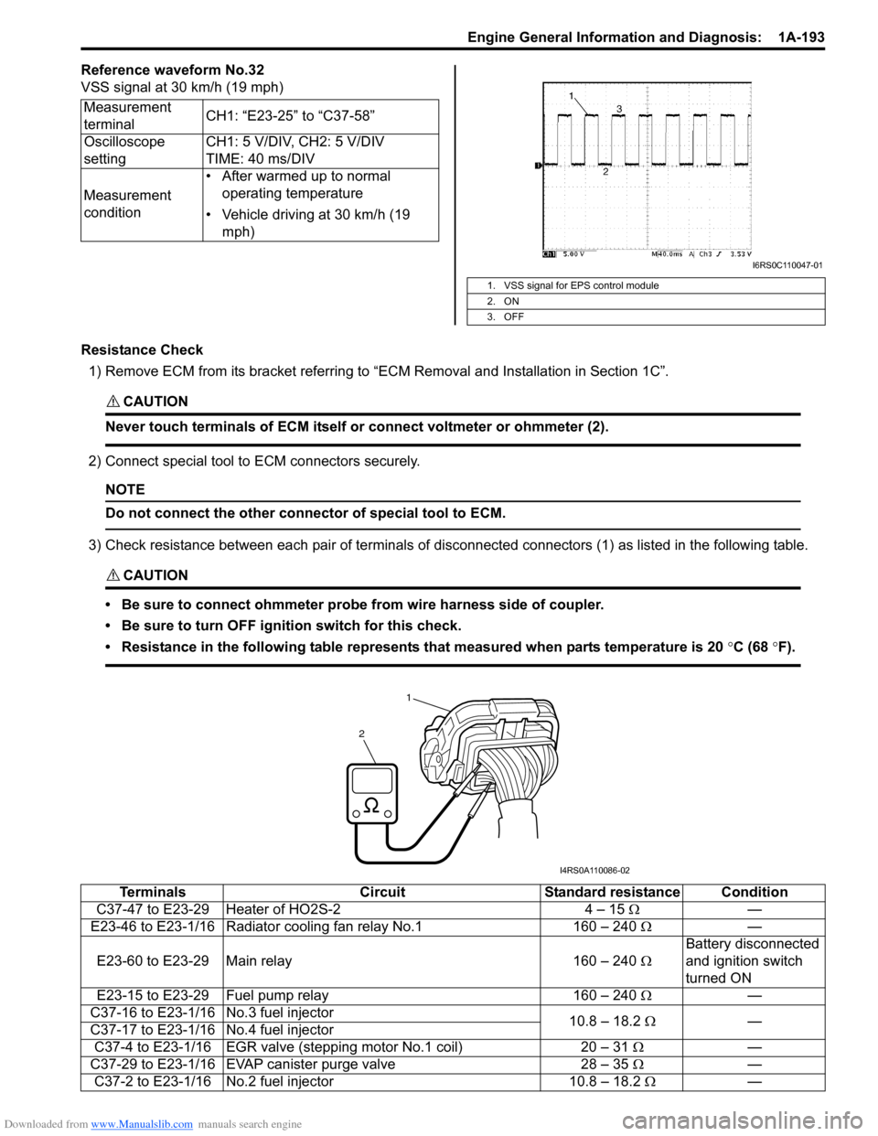
Reference waveform No.32
VSS signal at 30 km/h (19 mph)
Resistance Check1) Remove ECM from its bracket referring to “ECM Removal and Installation in Section 1C”.
CAUTION!
Never touch terminals of ECM itself or connect voltmeter or ohmmeter (2).
2) Connect special tool to ECM connectors securely.
NOTE
Do not connect the other connector of special tool to ECM.
3) Check resistance between each pair of terminals of disconnected connectors (1) as listed in the following table.
CAUTION!
• Be sure to connect ohmmeter probe from wire harness side of coupler.
• Be sure to turn OFF ignition switch for this check.
• Resistance in the following table represents that measured when parts temperature is 20 °C (68 °F).
Measurement
terminal CH1: “E23-25” to “C37-58”
Oscilloscope
setting CH1: 5 V/DIV, CH2: 5 V/DIV
TIME: 40 ms/DIV
Measurement
condition • After warmed up to normal
operating temperature
• Vehicle driving at 30 km/h (19 mph)
1. VSS signal for EPS control module
2. ON
3. OFF
I6RS0C110047-01
1
2
I4RS0A110086-02
Terminals CircuitStandard resistance Condition
C37-47 to E23-29 Heater of HO2S-2 4 – 15 Ω—
E23-46 to E23-1/16 Radiator cooling fan relay No.1 160 – 240 Ω —
E23-60 to E23-29 Main relay 160 – 240 ΩBattery disconnected
and ignition switch
turned ON
E23-15 to E23-29 Fuel pump relay 160 – 240 Ω —
C37-16 to E23-1/16 No.3 fuel injector 10.8 – 18.2 Ω —
C37-17 to E23-1/16 No.4 fuel injector
C37-4 to E23-1/16 EGR valve (st epping motor No.1 coil) 20 – 31 Ω —
C37-29 to E23-1/16 EVAP canister purge valve 28 – 35 Ω —
C37-2 to E23-1/16 No.2 fuel injector 10.8 – 18.2 Ω—
Page 278 of 1496
Downloaded from www.Manualslib.com manuals search engine 1C-6 Engine Electrical Devices:
APP Sensor Assembly InspectionS7RS0B1306007
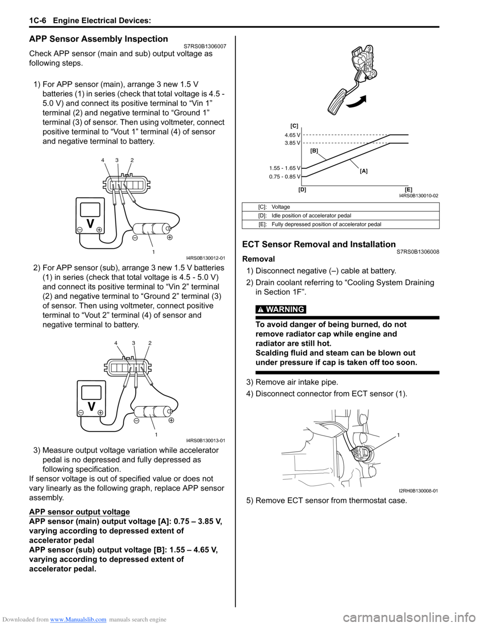
Check APP sensor (main and sub) output voltage as
following steps.
1) For APP sensor (main) , arrange 3 new 1.5 V
batteries (1) in series (check that total voltage is 4.5 -
5.0 V) and connect its positive terminal to “Vin 1”
terminal (2) and negative terminal to “Ground 1”
terminal (3) of sensor. Then using voltmeter, connect
positive terminal to “Vout 1” terminal (4) of sensor
and negative terminal to battery.
2) For APP sensor (s ub), arrange 3 new 1.5 V batteries
(1) in series (check that total voltage is 4.5 - 5.0 V)
and connect its positive terminal to “Vin 2” terminal
(2) and negative terminal to “Ground 2” terminal (3)
of sensor. Then using volt meter, connect positive
terminal to “Vout 2” terminal (4) of sensor and
negative termin al to battery.
3) Measure output voltage variation while accelerator pedal is no depressed and fully depressed as
following specification.
If sensor voltage is out of specified value or does not
vary linearly as the followin g graph, replace APP sensor
assembly.
APP sensor output voltage
APP sensor (main) output voltage [A]: 0.75 – 3.85 V,
varying according to depressed extent of
accelerator pedal
APP sensor (sub) output voltage [B]: 1.55 – 4.65 V,
varying according to depressed extent of
accelerator pedal.
ECT Sensor Removal and InstallationS7RS0B1306008
Removal
1) Disconnect negative (–) cable at battery.
2) Drain coolant referring to “Cooling System Draining in Section 1F”.
WARNING!
To avoid danger of being burned, do not
remove radiator cap while engine and
radiator are still hot.
Scalding fluid and steam can be blown out
under pressure if cap is taken off too soon.
3) Remove air intake pipe.
4) Disconnect connector from ECT sensor (1).
5) Remove ECT sensor from thermostat case.
1
234I4RS0B130012-01
1
234I4RS0B130013-01
[C]: Voltage
[D]: Idle position of accelerator pedal
[E]: Fully depressed position of accelerator pedal
[C]
[B]
[D] [E] [A]
4.65 V
3.85 V
1.55 - 1.65 V
0.75 - 0.85 V
I4RS0B130010-02
1
I2RH0B130008-01
Page 302 of 1496

Downloaded from www.Manualslib.com manuals search engine 1D-17 Engine Mechanical:
Engine Assembly Removal and InstallationS7RS0B1406011
NOTE
After replacing electric throttle body
assembly, perform calibration of throttle
valve referring to “Electric Throttle Body
System Calibration in Section 1C”.
Removal1) Relieve fuel pressure according to “Fuel Pressure Relief Procedure in Section 1G”.
2) Disconnect negative and pos itive cable at battery.
3) Remove battery and tray.
4) Remove engine hood after disconnecting windshield washer hose.
5) Remove right and left side engine under covers.
6) Remove A/C compressor belt by referring to “Compressor Drive Belt Remo val and Installation in
Section 7B” or “Compressor Drive Belt Removal and
Installation in Section 7B”.
7) Drain engine oil, transaxle oil and coolant.
8) Remove cowl top plate referring to “Cowl Top Components in Section 9K”.
9) Remove air cleaner assembly referring to “Air Cleaner Components”.
10) With hose connected, detach A/C compressor from its bracket (A/C model) referring to “Compressor
Assembly Removal and Installation in Section 7B” or
“Compressor Assembly Removal and Installation in
Section 7B”.
CAUTION!
Suspend removed A/C compressor at a place
where no damage will be caused during
removal and installation of engine assembly.
11) Remove intake manifold rear stiffener (1) from intake manifold and cylinder block. 12) Disconnect the following electric wires:
• MAP sensor (1)
• ECT sensor (2)
•EGR valve (3)
• CMP sensor (4)
• Electric throttle body assembly (5)
• Ignition coil assembly (6)
• Injectors (7)
• Heated oxygen sensor No. 2 (8) and No. 1 (9)
• Oil control valve (10)
• Engine oil pressure switch (11)
• CKP sensor (12)
• Knock sensor (13)
• Back up light switch (14)
• Generator (15)
• Starting motor (16)
• Ground terminal (17) from intake manifold
• Battery ground terminal (18) from exhaust manifold
• Battery ground cable (19) from transaxle
• Magnet clutch switch of A/C compressor (A/C model)
• Each wire harness clamps
• Output shaft speed sensor (VSS) (34) (A/T model)
• Solenoid valve (33) (A/T model)
• Transmission range sensor (32) (A/T model)
• Input shaft speed sensor (31) (A/T model)
13) Remove fuse box from its bracket.
14) Disconnect the following cables: • Gear select control cable (23) (M/T model)
• Gear shift control cable (24) (M/T model)
• A/T select cable (A/T model)
15) Disconnect the following hoses: • Brake booster hose (26) from intake manifold
• Radiator inlet and outlet hoses (20) from each pipe
• Heater inlet and outlet hoses (21) from each pipe
• Fuel feed hoses (22) from fuel feed pipe
• EVAP canister purge valve hose (30) from purge pipe
• A/T fluid cooler hoses (A/T model)
16) With hose connected, detach clutch operating cylinder (25). (M/T model)
CAUTION!
Suspend removed clutch operating cylinder
at a place where no damage will be caused
during removal and installation of engine
assembly.
1
I6RS0B141014-01
Page 370 of 1496
Downloaded from www.Manualslib.com manuals search engine 1F-7 Engine Cooling System:
Cooling System Flush and RefillS7RS0B1606005
WARNING!
To help avoid danger of being burned, do not
remove radiator cap while engine and
radiator are still hot. Scalding fluid and steam
can be blown out under pressure if cap is
taken off too soon.
NOTE
For detail of coolant specification, refer to
“Coolant Description”.
1) Remove radiator cap when engine is cool as follows.a) Turn cap counterclockwise slowly until it reaches a “stop” (Do not press down while turning it).
b) Wait until pressure is relieved (indicated by a hissing sound) then press down on cap and
continue to turn it counterclockwise.
2) With radiator cap removed, run engine until upper radiator hose is hot (this shows that thermostat is
open and coolant is flowing through system).
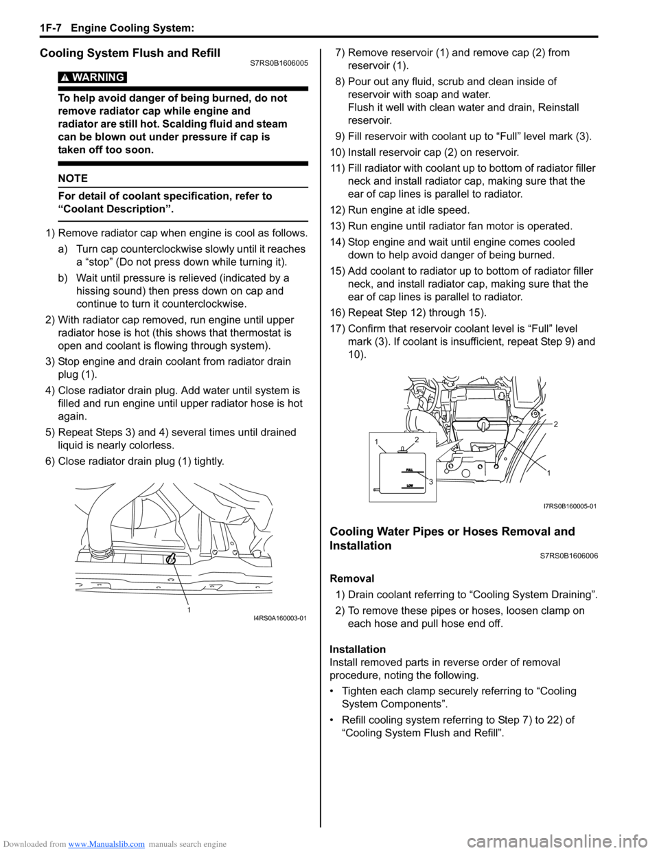
3) Stop engine and drain coolant from radiator drain plug (1).
4) Close radiator drain plug. Add water until system is filled and run engine until up per radiator hose is hot
again.
5) Repeat Steps 3) and 4) several times until drained liquid is nearly colorless.
6) Close radiator drain plug (1) tightly. 7) Remove reservoir (1) and remove cap (2) from
reservoir (1).
8) Pour out any fluid, scrub and clean inside of reservoir with soap and water.
Flush it well with clean water and drain, Reinstall
reservoir.
9) Fill reservoir with coolant up to “Full” level mark (3).
10) Install reservoir cap (2) on reservoir. 11) Fill radiator with coolant up to bottom of radiator filler neck and install radiator cap, making sure that the
ear of cap lines is parallel to radiator.
12) Run engine at idle speed.
13) Run engine until radiator fan motor is operated.
14) Stop engine and wait until engine comes cooled down to help avoid danger of being burned.
15) Add coolant to radiator up to bottom of radiator filler
neck, and install radiator ca p, making sure that the
ear of cap lines is parallel to radiator.
16) Repeat Step 12) through 15).
17) Confirm that reservoir cool ant level is “Full” level
mark (3). If coolant is insu fficient, repeat Step 9) and
10).
Cooling Water Pipes or Hoses Removal and
Installation
S7RS0B1606006
Removal
1) Drain coolant referring to “Cooling System Draining”.
2) To remove these pipes or hoses, loosen clamp on each hose and pull hose end off.
Installation
Install removed parts in reverse order of removal
procedure, noting the following.
• Tighten each clamp securely referring to “Cooling System Components”.
• Refill cooling system referrin g to Step 7) to 22) of
“Cooling System Flush and Refill”.
1I4RS0A160003-01
1
2
1
3
2
I7RS0B160005-01
Page 373 of 1496
Downloaded from www.Manualslib.com manuals search engine Engine Cooling System: 1F-10
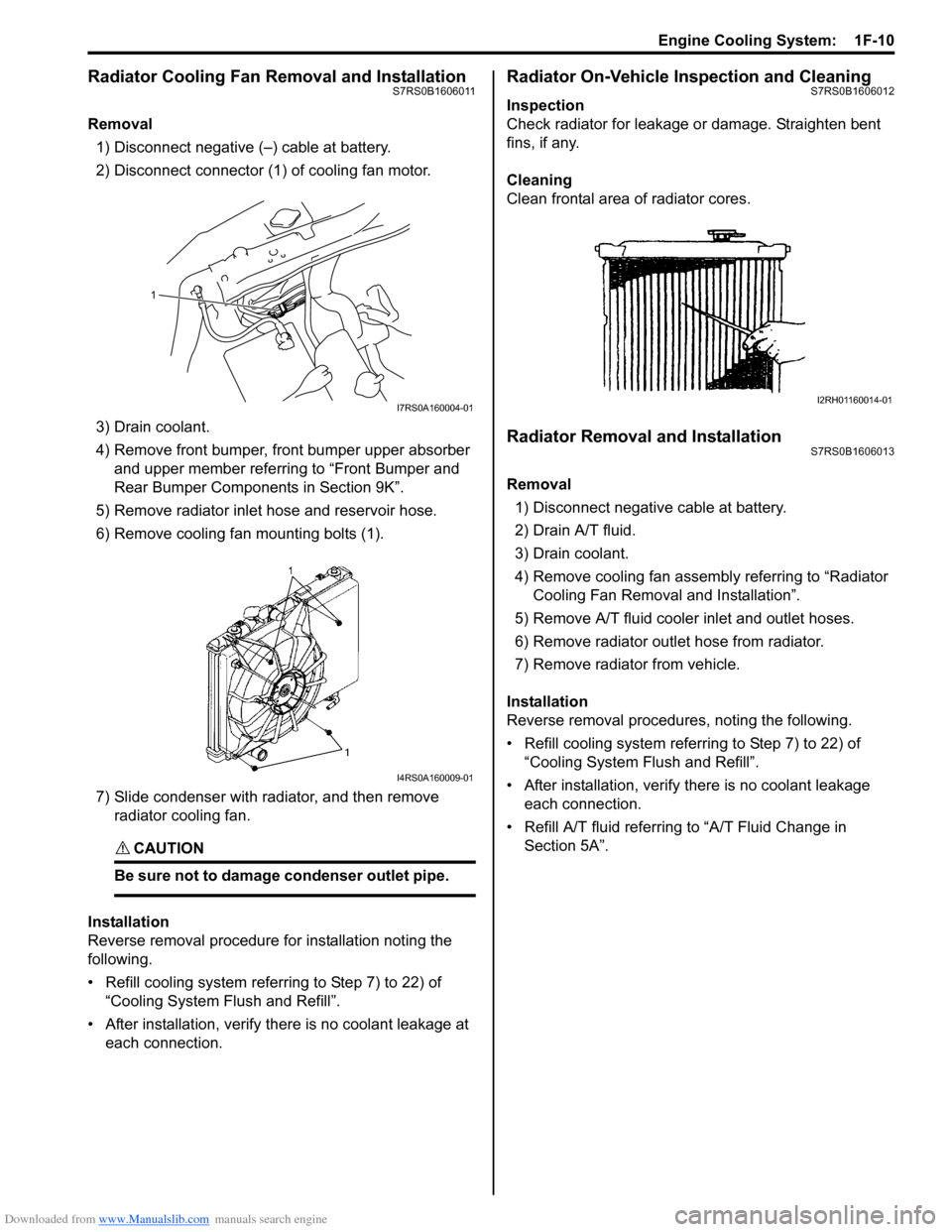
Radiator Cooling Fan Removal and InstallationS7RS0B1606011
Removal1) Disconnect negative (–) cable at battery.
2) Disconnect connector (1) of cooling fan motor.
3) Drain coolant.
4) Remove front bumper, front bumper upper absorber and upper member referring to “Front Bumper and
Rear Bumper Componen ts in Section 9K”.
5) Remove radiator inlet hose and reservoir hose.
6) Remove cooling fan mounting bolts (1).
7) Slide condenser with radiator, and then remove radiator cooling fan.
CAUTION!
Be sure not to damage condenser outlet pipe.
Installation
Reverse removal procedure for installation noting the
following.
• Refill cooling system referring to Step 7) to 22) of “Cooling System Fl ush and Refill”.
• After installation, verify there is no coolant leakage at each connection.
Radiator On-Vehicle Inspection and CleaningS7RS0B1606012
Inspection
Check radiator for leakage or damage. Straighten bent
fins, if any.
Cleaning
Clean frontal area of radiator cores.
Radiator Removal and InstallationS7RS0B1606013
Removal
1) Disconnect negative cable at battery.
2) Drain A/T fluid.
3) Drain coolant.
4) Remove cooling fan assemb ly referring to “Radiator
Cooling Fan Removal and Installation”.
5) Remove A/T fluid cooler inlet and outlet hoses.
6) Remove radiator outlet hose from radiator.
7) Remove radiator from vehicle.
Installation
Reverse removal procedures, noting the following.
• Refill cooling system referrin g to Step 7) to 22) of
“Cooling System Flush and Refill”.
• After installation, verify there is no coolant leakage each connection.
• Refill A/T fluid referring to “A/T Fluid Change in
Section 5A”.
1
I7RS0A160004-01
I4RS0A160009-01
I2RH01160014-01
Page 426 of 1496
Downloaded from www.Manualslib.com manuals search engine 1K-3 Exhaust System:
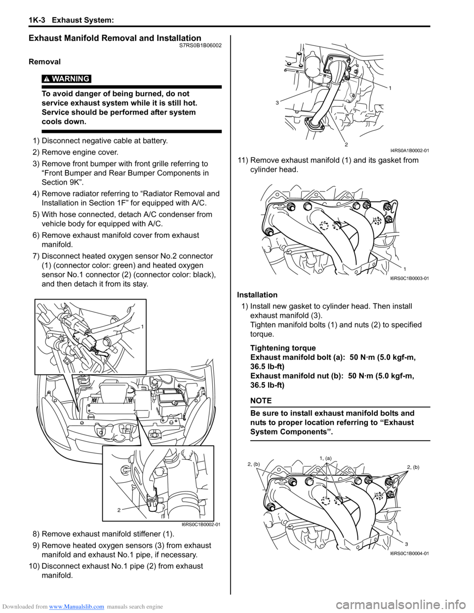
Exhaust Manifold Removal and InstallationS7RS0B1B06002
Removal
WARNING!
To avoid danger of being burned, do not
service exhaust system while it is still hot.
Service should be performed after system
cools down.
1) Disconnect negative cable at battery.
2) Remove engine cover.
3) Remove front bumper with front grille referring to
“Front Bumper and Rear Bumper Components in
Section 9K”.
4) Remove radiator referring to “Radiator Removal and Installation in Section 1F ” for equipped with A/C.
5) With hose connected, detach A/C condenser from vehicle body for equipped with A/C.
6) Remove exhaust manifold cover from exhaust manifold.
7) Disconnect heated oxygen sensor No.2 connector (1) (connector color: green) and heated oxygen
sensor No.1 connector (2) (connector color: black),
and then detach it from its stay.
8) Remove exhaust manifold stiffener (1).
9) Remove heated oxygen sensors (3) from exhaust manifold and exhaust No.1 pipe, if necessary.
10) Disconnect exhaust No.1 pipe (2) from exhaust manifold. 11) Remove exhaust manifold (1) and its gasket from
cylinder head.
Installation 1) Install new gasket to cylinder head. Then install exhaust manifold (3).
Tighten manifold bolts (1) and nuts (2) to specified
torque.
Tightening torque
Exhaust manifold bolt (a): 50 N·m (5.0 kgf-m,
36.5 lb-ft)
Exhaust manifold nut (b): 50 N·m (5.0 kgf-m,
36.5 lb-ft)
NOTE
Be sure to install exhaust manifold bolts and
nuts to proper location referring to “Exhaust
System Components”.
1
2
I6RS0C1B0002-01
1
2
3
I4RS0A1B0002-01
1
I6RS0C1B0003-01
2, (b) 2, (b)
3
1, (a)
I6RS0C1B0004-01
Page 427 of 1496
Downloaded from www.Manualslib.com manuals search engine Exhaust System: 1K-4
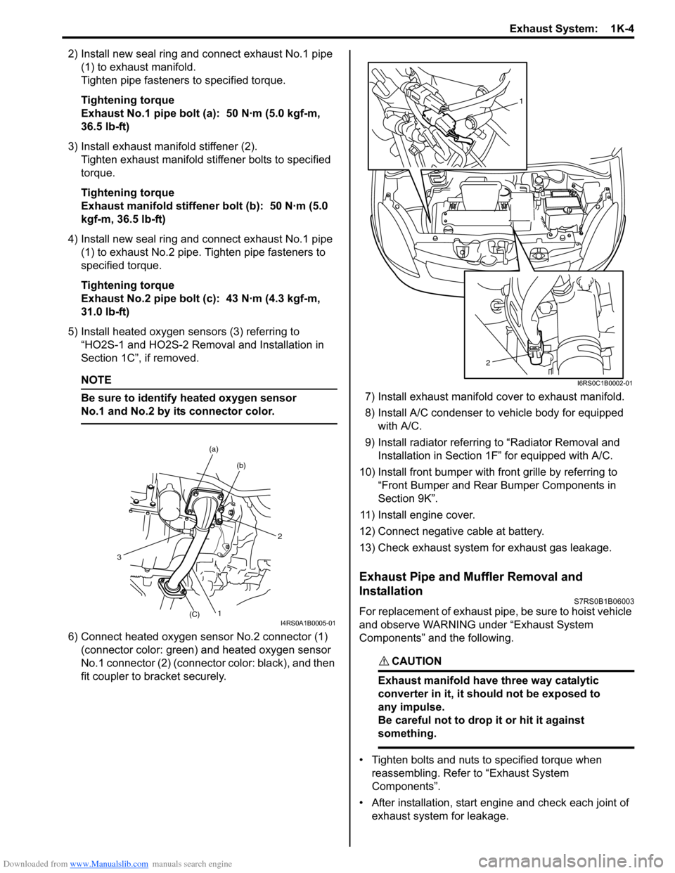
2) Install new seal ring and connect exhaust No.1 pipe (1) to exhaust manifold.
Tighten pipe fasteners to specified torque.
Tightening torque
Exhaust No.1 pipe bolt (a): 50 N·m (5.0 kgf-m,
36.5 lb-ft)
3) Install exhaust manifold stiffener (2). Tighten exhaust manifold stiffener bolts to specified
torque.
Tightening torque
Exhaust manifold stiffener bolt (b): 50 N·m (5.0
kgf-m, 36.5 lb-ft)
4) Install new seal ring and connect exhaust No.1 pipe (1) to exhaust No.2 pipe. Tighten pipe fasteners to
specified torque.
Tightening torque
Exhaust No.2 pipe bolt (c): 43 N·m (4.3 kgf-m,
31.0 lb-ft)
5) Install heated oxygen sensors (3) referring to “HO2S-1 and HO2S-2 Removal and Installation in
Section 1C”, if removed.
NOTE
Be sure to identify heated oxygen sensor
No.1 and No.2 by its connector color.
6) Connect heated oxygen sensor No.2 connector (1)
(connector color: green) and heated oxygen sensor
No.1 connector (2) (connector color: black), and then
fit coupler to br acket securely. 7) Install exhaust manifold cover to exhaust manifold.
8) Install A/C condenser to vehicle body for equipped
with A/C.
9) Install radiator referrin g to “Radiator Removal and
Installation in Section 1F” for equipped with A/C.
10) Install front bumper with fr ont grille by referring to
“Front Bumper and Rear Bumper Components in
Section 9K”.
11) Install engine cover.
12) Connect negative cable at battery.
13) Check exhaust system for exhaust gas leakage.
Exhaust Pipe and Muffler Removal and
Installation
S7RS0B1B06003
For replacement of exhaust pipe, be sure to hoist vehicle
and observe WARNING under “Exhaust System
Components” and the following.
CAUTION!
Exhaust manifold have three way catalytic
converter in it, it should not be exposed to
any impulse.
Be careful not to drop it or hit it against
something.
• Tighten bolts and nuts to specified torque when reassembling. Refer to “Exhaust System
Components”.
• After installation, start engine and check each joint of exhaust system for leakage.
2
(b)
(a)
1(C)
3
I4RS0A1B0005-01
1
2
I6RS0C1B0002-01
Page 940 of 1496
Downloaded from www.Manualslib.com manuals search engine 7A-4 Heater and Ventilation:
Repair Instructions
HVAC Unit ComponentsS7RS0B7106001
For manual type A/C, refer to “HVAC Unit Components
in Section 7B”.
For automatic type A/C, refer to “HVAC Unit
Components in Section 7B”.
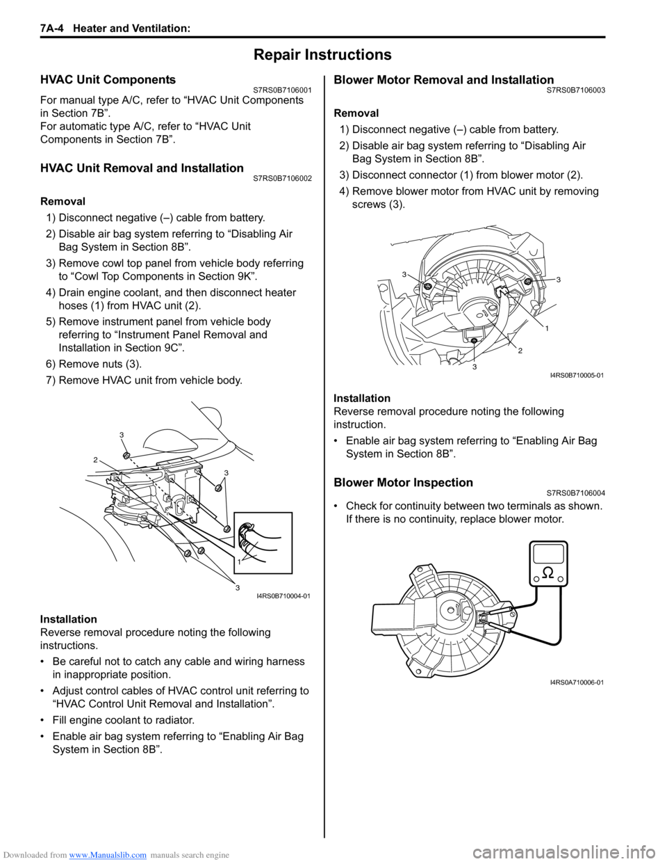
HVAC Unit Removal and InstallationS7RS0B7106002
Removal
1) Disconnect negative (–) cable from battery.
2) Disable air bag system referring to “Disabling Air Bag System in Section 8B”.
3) Remove cowl top panel from vehicle body referring to “Cowl Top Components in Section 9K”.
4) Drain engine coolant, and then disconnect heater hoses (1) from HVAC unit (2).
5) Remove instrument panel from vehicle body referring to “Instrument Panel Removal and
Installation in Section 9C”.
6) Remove nuts (3).
7) Remove HVAC unit from vehicle body.
Installation
Reverse removal procedure noting the following
instructions.
• Be careful not to catch any cable and wiring harness in inappropriate position.
• Adjust control cables of HVAC control unit referring to “HVAC Control Unit Remo val and Installation”.
• Fill engine coolant to radiator.
• Enable air bag system referring to “Enabling Air Bag System in Section 8B”.
Blower Motor Removal and InstallationS7RS0B7106003
Removal
1) Disconnect negative (–) cable from battery.
2) Disable air bag system referring to “Disabling Air Bag System in Section 8B”.
3) Disconnect connector (1) from blower motor (2).
4) Remove blower motor from HVAC unit by removing screws (3).
Installation
Reverse removal procedure noting the following
instruction.
• Enable air bag system referring to “Enabling Air Bag System in Section 8B”.
Blower Motor InspectionS7RS0B7106004
• Check for continuity between two terminals as shown. If there is no continuity, replace blower motor.
3
2
3
1
3I4RS0B710004-01
3
1
2
3
3
I4RS0B710005-01
I4RS0A710006-01