cord break SUZUKI SWIFT 2008 2.G Service Workshop Manual
[x] Cancel search | Manufacturer: SUZUKI, Model Year: 2008, Model line: SWIFT, Model: SUZUKI SWIFT 2008 2.GPages: 1496, PDF Size: 34.44 MB
Page 326 of 1496

Downloaded from www.Manualslib.com manuals search engine 1D-41 Engine Mechanical:
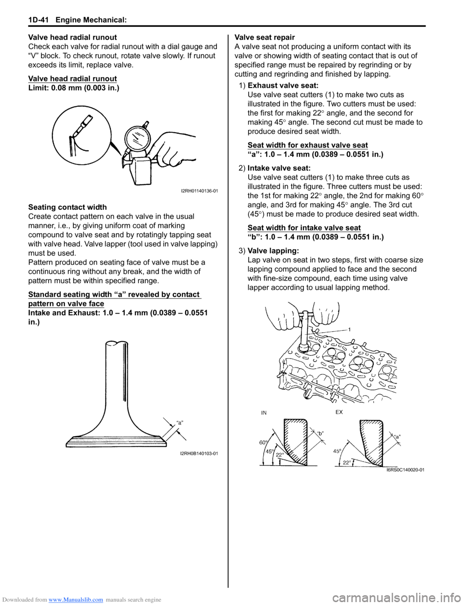
Valve head radial runout
Check each valve for radial runout with a dial gauge and
“V” block. To check runout, rotate valve slowly. If runout
exceeds its limit, replace valve.
Valve head radial runout
Limit: 0.08 mm (0.003 in.)
Seating contact width
Create contact pattern on each valve in the usual
manner, i.e., by giving uniform coat of marking
compound to valve seat and by rotatingly tapping seat
with valve head. Valve lapper (tool used in valve lapping)
must be used.
Pattern produced on seating face of valve must be a
continuous ring without any break, and the width of
pattern must be within specified range.
Standard seating width “a” revealed by contact
pattern on valve face
Intake and Exhaust: 1.0 – 1.4 mm (0.0389 – 0.0551
in.)Valve seat repair
A valve seat not producing
a uniform contact with its
valve or showing width of seating contact that is out of
specified range must be repaired by regrinding or by
cutting and regrinding and finished by lapping.
1) Exhaust valve seat:
Use valve seat cutters (1 ) to make two cuts as
illustrated in the figure. Two cutters must be used:
the first for making 22 ° angle, and the second for
making 45 ° angle. The second cut must be made to
produce desired seat width.
Seat width for exhaust valve seat
“a”: 1.0 – 1.4 mm (0.0389 – 0.0551 in.)
2) Intake valve seat:
Use valve seat cutters (1) to make three cuts as
illustrated in the figure. Th ree cutters must be used:
the 1st for making 22 ° angle, the 2nd for making 60 °
angle, and 3rd for making 45 ° angle. The 3rd cut
(45 °) must be made to produce desired seat width.
Seat width for intake valve seat
“b”: 1.0 – 1.4 mm (0.0389 – 0.0551 in.)
3) Valve lapping:
Lap valve on seat in two steps, first with coarse size
lapping compound applied to face and the second
with fine-size compound, each time using valve
lapper according to usual lapping method.
I2RH01140136-01
I2RH0B140103-01
I6RS0C140020-01
Page 469 of 1496

Downloaded from www.Manualslib.com manuals search engine Wheels and Tires: 2D-2
Lower than recommended pressure can cause:
• Tire squeal on turns
• Hard Steering
• Rapid and uneven wear on the edges of the tread
• Tire rim bruises and rupture
• Tire cord breakage
• High tire temperature
• Reduced handling
• High fuel consumption
Replacement Tires
When replacement is necessary, the original equipment
type tire should be used. Refer to the Tire Placard.
Replacement tires should be of the same size, load
range and construction as those originally on the vehicle.
Use of any other size or type tire may affect ride,
handling, speedometer / odometer calibration, vehicle
ground clearance and tire or snow chain clearance to the
body and chassis.
It is recommended that new tires be installed in pairs on
the same axle. If necessary to replace only one tire, it
should be paired with the tire having the most tread, to
equalize braking traction.
WARNING!
Do not mix different types of tires on the
same vehicle such as radial, bias and bias-
belted tires except in emergencies, because
handling may be seriously affected and may
result in loss of control.
The metric term for tire infl ation pressure is the kilo
pascal (kPa). Tire pressures is usually printed in both
kPa and kgf/cm
2 on the “Tire Placard”.
Metric tire gauges are available from tool suppliers.
The chart, shown the table, converts commonly used
inflation pressures from kPa to kgf/cm
2 and psi.
Wheels DescriptionS7RS0B2401002
Wheel Maintenance
Wheel repairs that use welding, heating, or peening are
not approved. All damaged wheels should be replaced.
Replacement Wheels
Wheels must be replaced if they are bent, dented, have
excessive lateral or radial runout, air leak through welds,
have elongated bolt holes, if lug wheel bolts won’t stay
tight, or if they are heavily rusted. Wheels with greater
runout than shown in the following may cause
objectional vibrations.
Replacement wheels must be equivalent to the original
equipment wheels in load capacity, diameter, rim with
offset and mounting configuration. A wheel of improper
size or type may affect wheel and bearing life, brake
cooling, speedometer / odometer calibration, vehicle
ground clearance and tire clearance to body and
chassis.
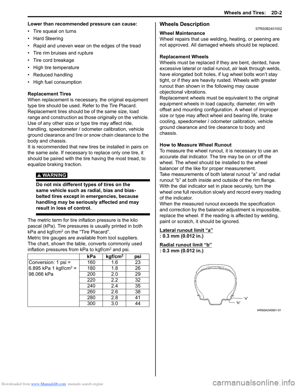
How to Measure Wheel Runout
To measure the wheel runout, it is necessary to use an
accurate dial indicator. The tire may be on or off the
wheel. The wheel should be installed to the wheel
balancer of the like for proper measurement.
Take measurements of both lateral runout “a” and radial
runout “b” at both inside an d outside of the rim flange.
With the dial indicator set in place securely, turn the
wheel one full revolution slowly and record every reading
of the indicator.
When the measured runout exceeds the specification
and correction by the balancer adjustment is impossible,
replace the wheel. If the reading is affected by welding,
paint or scratch, it should be ignored.
Lateral runout limit “a”
: 0.3 mm (0.012 in.)
Radial runout limit “b”
: 0.3 mm (0.012 in.)
kPa kgf/cm2psi
Conversion: 1 psi =
6.895 kPa 1 kgf/cm
2 =
98.066 kPa 160 1.6 23
180 1.8 26
200 2.0 29
220 2.2 32
240 2.4 35
260 2.6 38
280 2.8 41
300 3.0 44
I4RS0A240001-01
Page 1359 of 1496

Downloaded from www.Manualslib.com manuals search engine Security and Locks: 9F-13
Replacement of Transmitter Battery S7RS0B9606014
If transmitter becomes unreliable, replace transmitter
battery as follows.
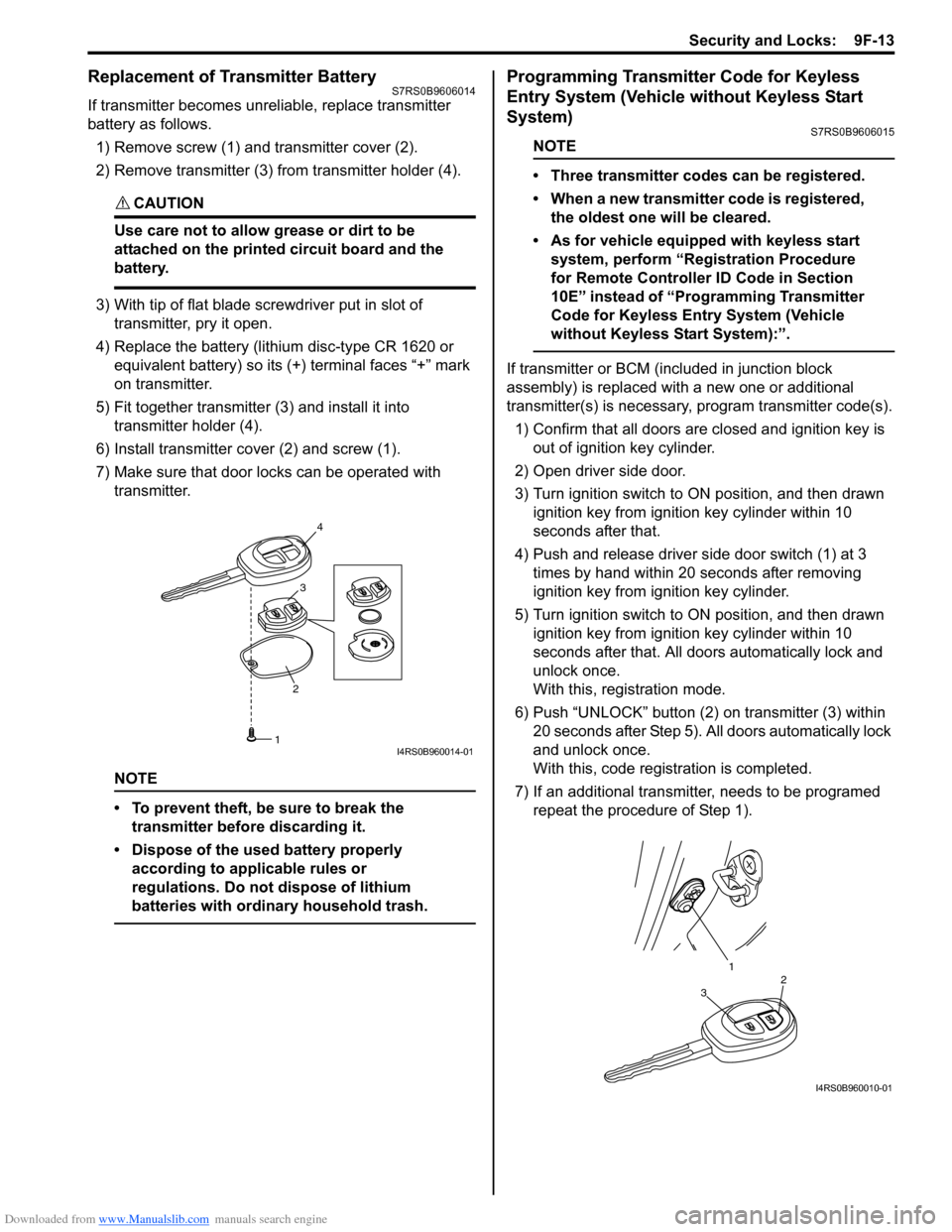
1) Remove screw (1) and transmitter cover (2).
2) Remove transmitter (3) from transmitter holder (4).
CAUTION!
Use care not to allow grease or dirt to be
attached on the printed circuit board and the
battery.
3) With tip of flat blade screwdriver put in slot of transmitter, pry it open.
4) Replace the battery (lithium disc-type CR 1620 or equivalent battery) so its (+) terminal faces “+” mark
on transmitter.
5) Fit together transmitter (3) and install it into
transmitter holder (4).
6) Install transmitter co ver (2) and screw (1).
7) Make sure that door locks can be operated with transmitter.
NOTE
• To prevent theft, be sure to break the transmitter before discarding it.
• Dispose of the used battery properly according to applicable rules or
regulations. Do not dispose of lithium
batteries with ordinary household trash.
Programming Transmitter Code for Keyless
Entry System (Vehicle without Keyless Start
System)
S7RS0B9606015
NOTE
• Three transmitter codes can be registered.
• When a new transmitter code is registered, the oldest one will be cleared.
• As for vehicle equipped with keyless start system, perform “Registration Procedure
for Remote Controller ID Code in Section
10E” instead of “Programming Transmitter
Code for Keyless Entry System (Vehicle
without Keyless Start System):”.
If transmitter or BCM (included in junction block
assembly) is replaced with a new one or additional
transmitter(s) is necessary, program transmitter code(s).
1) Confirm that all doors are closed and ignition key is
out of ignition key cylinder.
2) Open driver side door.
3) Turn ignition switch to ON position, and then drawn ignition key from igniti on key cylinder within 10
seconds after that.
4) Push and release driver side door switch (1) at 3 times by hand within 20 seconds after removing
ignition key from ig nition key cylinder.
5) Turn ignition switch to ON position, and then drawn ignition key from igniti on key cylinder within 10
seconds after that. All d oors automatically lock and
unlock once.
With this, registration mode.
6) Push “UNLOCK” button (2) on transmitter (3) within
20 seconds after Step 5). All doors automatically lock
and unlock once.
With this, code registration is completed.
7) If an additional transmitter, needs to be programed repeat the procedure of Step 1).
23
4
1I4RS0B960014-01
1
32
I4RS0B960010-01
Page 1495 of 1496

Downloaded from www.Manualslib.com manuals search engine Keyless Start System: 10E-33
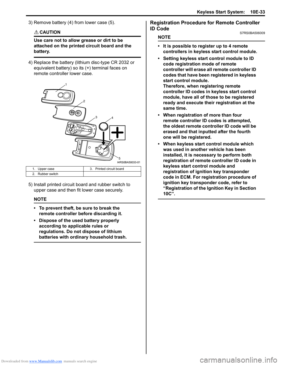
3) Remove battery (4) from lower case (5).
CAUTION!
Use care not to allow grease or dirt to be
attached on the printed circuit board and the
battery.
4) Replace the battery (lithium disc-type CR 2032 or equivalent battery) so its (+) terminal faces on
remote controller lower case.
5) Install printed circuit board and rubber switch to upper case and then fit lower case securely.
NOTE
• To prevent theft, be sure to break the remote controller be fore discarding it.
• Dispose of the used battery properly according to applicable rules or
regulations. Do not dispose of lithium
batteries with ordinary household trash.
Registration Procedure for Remote Controller
ID Code
S7RS0BA506009
NOTE
• It is possible to register up to 4 remote controllers in keyless start control module.
• Setting keyless start control module to ID code registration mode of remote
controller will erase all remote controller ID
codes that have been registered in keyless
start control module.
Therefore, when re gistering remote
controller ID codes in keyless start control
module, have all of those to be registered
ready and execute their registration at the
same time.
• When registration of more than four remote controller ID codes is attempted,
the oldest remote cont roller ID code will be
erased and that inputted after the fourth
one will be registered.
• When keyless start control module which was used in another vehicle has been
installed, it is nece ssary to perform both
registration of remote controller ID code in
keyless start control module and
registration of ignition key transponder
code in ECM. For registration procedure of
ignition key transponder code, refer to
“Registration of the Ignition Key in Section
10C”.
1. Upper case 3. Printed circuit board
2. Rubber switch
1
2
34
5I4RS0BA50033-01