exhaust removal SUZUKI SWIFT 2008 2.G Service Workshop Manual
[x] Cancel search | Manufacturer: SUZUKI, Model Year: 2008, Model line: SWIFT, Model: SUZUKI SWIFT 2008 2.GPages: 1496, PDF Size: 34.44 MB
Page 34 of 1496
Downloaded from www.Manualslib.com manuals search engine 0B-4 Maintenance and Lubrication:
Accessory Drive Belt ReplacementS7RS0B0206002
Water Pump and Generator Drive Belt
Replace belt with new one referring to “Water Pump /
Generator Drive Belt Removal and Installation in Section
1J”.
A/C Compressor Drive Belt
Replace belt with new one referring to “Compressor
Drive Belt Removal and Inst allation in Section 7B”.
Valve Lash (Clearance) InspectionS7RS0B0206003
Inspect intake and exhaust valve lash and adjust as
necessary.
Refer to “Valve Lash (Clearance) Inspection in Section
1D” for valve lash inspection and adjustment procedure.
Engine Oil and Filter ChangeS7RS0B0206004
WARNING!
• New and used engine oil can be
hazardous.
Be sure to read “WARNING” in “General
Precautions in Section 00” and observe
what is written there.
• Step 1) – 7) outlined below must be performed with ENGINE NOT RUNNING.
For Step 8), be sure to have adequate
ventilation while engine is running.
Before draining engine oil, check engine for oil leakage.
If any evidence of leakage is found, make sure to correct
defective part before proceeding to the following work.
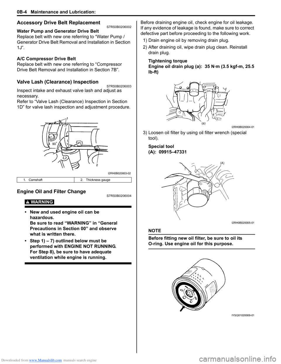
1) Drain engine oil by removing drain plug.
2) After draining oil, wipe drain plug clean. Reinstall drain plug.
Tightening torque
Engine oil drain plug (a): 35 N·m (3.5 kgf-m, 25.5
lb-ft)
3) Loosen oil filter by using oil filter wrench (special
tool).
Special tool
(A): 09915–47331
NOTE
Before fitting new oil filter, be sure to oil its
O-ring. Use engine oil for this purpose.
1. Camshaft 2. Thickness gauge
I2RH0B020003-02
I2RH0B020004-01
I2RH0B020005-01
IYSQ01020009-01
Page 36 of 1496
Downloaded from www.Manualslib.com manuals search engine 0B-6 Maintenance and Lubrication:
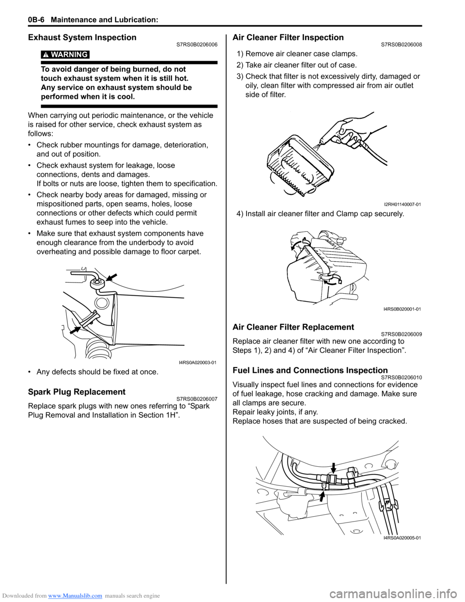
Exhaust System InspectionS7RS0B0206006
WARNING!
To avoid danger of being burned, do not
touch exhaust system when it is still hot.
Any service on exhaust system should be
performed when it is cool.
When carrying out periodic maintenance, or the vehicle
is raised for other service, check exhaust system as
follows:
• Check rubber mountings for damage, deterioration, and out of position.
• Check exhaust system for leakage, loose connections, dents and damages.
If bolts or nuts are loose, tighten them to specification.
• Check nearby body areas for damaged, missing or mispositioned parts, ope n seams, holes, loose
connections or other defects which could permit
exhaust fumes to seep into the vehicle.
• Make sure that exhaust system components have enough clearance from the underbody to avoid
overheating and possible damage to floor carpet.
• Any defects should be fixed at once.
Spark Plug ReplacementS7RS0B0206007
Replace spark plugs with new ones referring to “Spark
Plug Removal and Installation in Section 1H”.
Air Cleaner Filter InspectionS7RS0B0206008
1) Remove air cleaner case clamps.
2) Take air cleaner filter out of case.
3) Check that filter is not excessively dirty, damaged or oily, clean filter with compressed air from air outlet
side of filter.
4) Install air cleaner filter and Clamp cap securely.
Air Cleaner Filter ReplacementS7RS0B0206009
Replace air cleaner filter with new one according to
Steps 1), 2) and 4) of “Air Cleaner Filter Inspection”.
Fuel Lines and Connections InspectionS7RS0B0206010
Visually inspect fuel lines and connections for evidence
of fuel leakage, hose cracking and damage. Make sure
all clamps are secure.
Repair leaky joints, if any.
Replace hoses that are suspected of being cracked.
I4RS0A020003-01
I2RH01140007-01
I4RS0B020001-01
I4RS0A020005-01
Page 42 of 1496
Downloaded from www.Manualslib.com manuals search engine 0B-12 Maintenance and Lubrication:
HVAC Air Filter (If Equipped) InspectionS7RS0B0206032
1) Remove HVAC air filter from HVAC unit referring to
“HVAC Air Filter Removal and Installation (If
Equipped) in Section 7A”.
2) Check for dirt and dust. If HVAC air filter is excessively dirty, replace HVAC air filter with new
one. If not, go to next step.
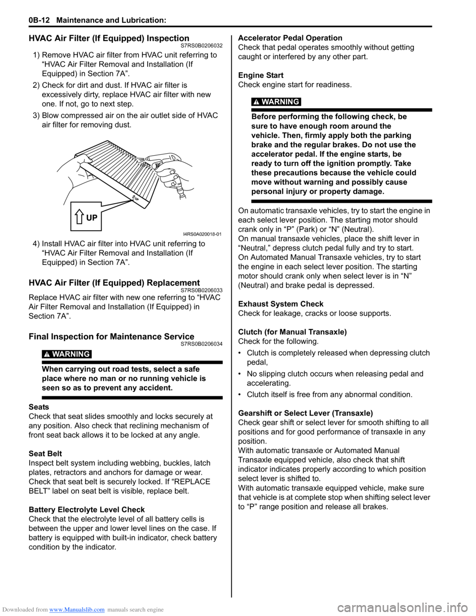
3) Blow compressed air on the air outlet side of HVAC air filter for removing dust.
4) Install HVAC air filter in to HVAC unit referring to
“HVAC Air Filter Removal and Installation (If
Equipped) in Section 7A”.
HVAC Air Filter (If Equipped) ReplacementS7RS0B0206033
Replace HVAC air filter with new one referring to “HVAC
Air Filter Removal and Installation (If Equipped) in
Section 7A”.
Final Inspection for Maintenance ServiceS7RS0B0206034
WARNING!
When carrying out road tests, select a safe
place where no man or no running vehicle is
seen so as to prevent any accident.
Seats
Check that seat slides smoot hly and locks securely at
any position. Also check that reclining mechanism of
front seat back allows it to be locked at any angle.
Seat Belt
Inspect belt system including webbing, buckles, latch
plates, retractors and anchors for damage or wear.
Check that seat belt is securely locked. If “REPLACE
BELT” label on seat belt is visible, replace belt.
Battery Electrolyte Level Check
Check that the electrolyte le vel of all battery cells is
between the upper and lower level lines on the case. If
battery is equipped with built-in indicator, check battery
condition by the indicator. Accelerator Pedal Operation
Check that pedal operates
smoothly without getting
caught or interfered by any other part.
Engine Start
Check engine start for readiness.
WARNING!
Before performing th e following check, be
sure to have enough room around the
vehicle. Then, firmly apply both the parking
brake and the regular brakes. Do not use the
accelerator pedal. If the engine starts, be
ready to turn off the ignition promptly. Take
these precautions because the vehicle could
move without warning and possibly cause
personal injury or property damage.
On automatic transaxle vehicles, try to start the engine in
each select lever position. The starting motor should
crank only in “P” (Park) or “N” (Neutral).
On manual transaxle vehicles, place the shift lever in
“Neutral,” depress clutch pedal fully and try to start.
On Automated Manual Transaxl e vehicles, try to start
the engine in each select le ver position. The starting
motor should crank only when select lever is in “N”
(Neutral) and brake pedal is depressed.
Exhaust System Check
Check for leakage, cracks or loose supports.
Clutch (for Manual Transaxle)
Check for the following.
• Clutch is completely released when depressing clutch pedal,
• No slipping clutch occurs when releasing pedal and accelerating.
• Clutch itself is free fr om any abnormal condition.
Gearshift or Select Lever (Transaxle)
Check gear shift or select lever for smooth shifting to all
positions and for good performance of transaxle in any
position.
With automatic transaxle or Automated Manual
Transaxle equipped vehicle, also check that shift
indicator indicates properly according to which position
select lever is shifted to.
With automatic transaxle equipped vehicle, make sure
that vehicle is at complete stop when shifting select lever
to “P” range position and release all brakes.
I4RS0A020018-01
Page 49 of 1496
Downloaded from www.Manualslib.com manuals search engine Table of Contents 1-v
Ignition Timing Inspection ................................... 1H-8
Specifications ....................................................... 1H-9
Tightening Torque Specifications ........................ 1H-9
Special Tools and Equipmen t ............................. 1H-9
Special Tool ........................................................ 1H-9
Starting System ................. ........................ 1I-1
Schematic and Routing Diagram ......................... 1I-1
Cranking System Circuit Diagram ........................ 1I-1
Diagnostic Information and Procedures ............. 1I-1
Cranking System Symptom Diagnosis ................. 1I-1
Cranking System Test.......................................... 1I-3
Repair Instructions ............................................... 1I-4 Starting Motor Dismounting and Remounting ...... 1I-4
Starting Motor Components ................................. 1I-5
Starting Motor Inspection ..................................... 1I-6
Specifications ........................................................ 1I-9
Cranking System Specifications........................... 1I-9
Tightening Torque Specifications ......................... 1I-9
Special Tools and Equipment .............................. 1I-9
Recommended Service Material .......................... 1I-9
Charging System ............ .......................... 1J-1
General Description ......... .................................... 1J-1
Battery Description ...............................................1J-1
Generator Descripti on ..........................................1J-2
Diagnostic Information and Procedures ............ 1J-4 Battery Inspection ................................................1J-4
Generator Symptom Diagnosis ............................1J-4 Generator Test (Undercharged Battery
Check) ............................................................... 1J-5
Generator Test (Overcharg ed Battery Check) .... 1J-6
Repair Instructions ........... ................................... 1J-6
Jump Starting in Case of Emergency.................. 1J-6
Battery Dismounting and Remounting ................ 1J-7
Water Pump / Generator Drive Belt Tension Inspection and Adjustment ................................ 1J-7
Water Pump / Generator Drive Belt Removal and Installation .................................................. 1J-8
Generator Unit Co mponents ............................... 1J-9
Generator Dismounting a nd Remounting............ 1J-9
Generator Components........ ............................. 1J-10
Generator Insp ection......................................... 1J-11
Specifications ..................................................... 1J-13 Charging System Specifications ....................... 1J-13
Tightening Torque Specifications ...................... 1J-13
Exhaust System .............. ......................... 1K-1
General Description .............................................1K-1
Exhaust System Description ............................... 1K-1
Diagnostic Information and Procedures ............1K-1 Exhaust System Check ....................................... 1K-1
Repair Instructions ........... ...................................1K-2
Exhaust System Components ............................. 1K-2
Exhaust Manifold Removal and Installation ........ 1K-3
Exhaust Pipe and Muffler Removal and Installation ......................................................... 1K-4
Specifications .................... ...................................1K-5
Tightening Torque Specifications ........................ 1K-5
Page 279 of 1496
Downloaded from www.Manualslib.com manuals search engine Engine Electrical Devices: 1C-7
Installation
Reverse removal procedure noting the following.
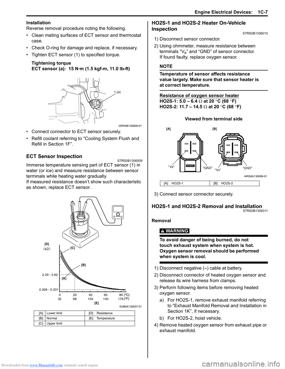
• Clean mating surfaces of ECT sensor and thermostat case.
• Check O-ring for damage and replace, if necessary.
• Tighten ECT sensor (1) to specified torque.
Tightening torque
ECT sensor (a): 15 N·m (1.5 kgf-m, 11.0 lb-ft)
• Connect connector to ECT sensor securely.
• Refill coolant referring to “Cooling System Flush and
Refill in Section 1F”.
ECT Sensor InspectionS7RS0B1306009
Immerse temperature sensing part of ECT sensor (1) in
water (or ice) and measure resistance between sensor
terminals while heating water gradually.
If measured resistance doesn’t show such characteristic
as shown, replace ECT sensor.
HO2S-1 and HO2S-2 Heater On-Vehicle
Inspection
S7RS0B1306010
1) Disconnect sensor connector.
2) Using ohmmeter, measure resistance between terminals “V
B” and “GND” of sensor connector.
If found faulty, replace oxygen sensor.
NOTE
Temperature of sensor affects resistance
value largely. Make sure that sensor heater is
at correct temperature.
Resistance of oxygen sensor heater
HO2S-1: 5.0 – 6.4 Ω at 20 °C (68 °F)
HO2S-2: 11.7 – 14.5 Ω at 20 °C (68 °F)
Viewed from terminal side
3) Connect sensor co nnector securely.
HO2S-1 and HO2S-2 Removal and InstallationS7RS0B1306011
Removal
WARNING!
To avoid danger of being burned, do not
touch exhaust system when system is hot.
Oxygen sensor removal should be performed
when system is cool.
1) Disconnect negative (–) cable at battery.
2) Disconnect connector of heated oxygen sensor and
release its wire harness from clamps.
3) Perform following items before removing heated oxygen sensor.
a) For HO2S-1, remove exhaust manifold referring to “Exhaust Manifold Remo val and Installation in
Section 1K”, if necessary.
b) For HO2S-2, hoist vehicle.
4) Remove heated oxygen sensor from exhaust pipe or exhaust manifold.
[A]: Lower limit [D]: Resistance
[B]: Normal [E]: Temperature
[C]: Upper limit
1,(a)
I2RH0B130009-01
20
0
68
32 104 140 176 40 60 80
[E]
2.29 - 2.62
0.309 - 0.331
[A]
[B]
[C][D]
I5JB0A130037-01
[A]: HO2S-1 [B]: HO2S-2
I4RS0A130006-01
Page 280 of 1496
Downloaded from www.Manualslib.com manuals search engine 1C-8 Engine Electrical Devices:
Installation
Reverse removal procedure noting the following.
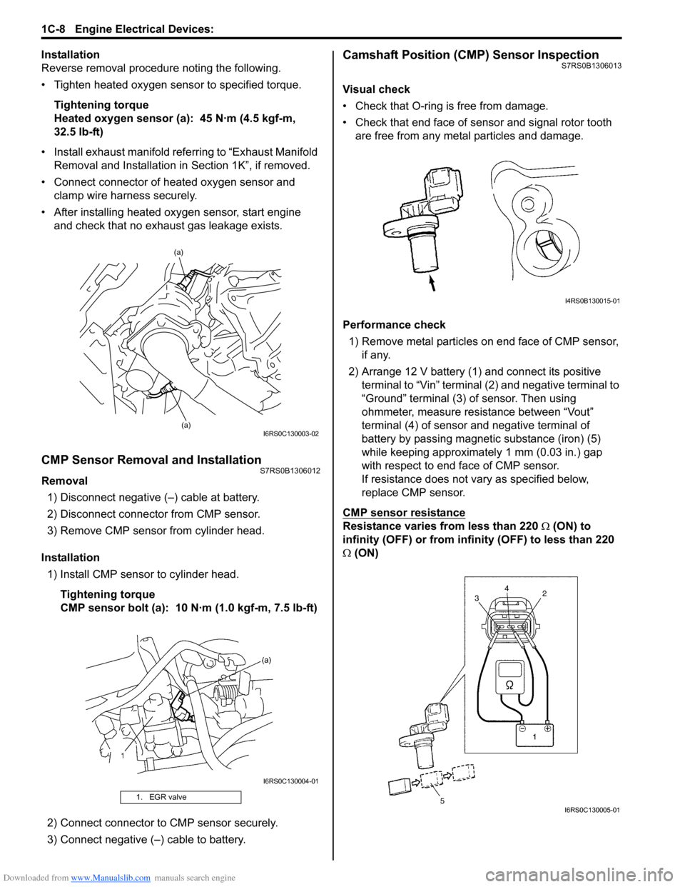
• Tighten heated oxygen sensor to specified torque.Tightening torque
Heated oxygen sensor (a): 45 N·m (4.5 kgf-m,
32.5 lb-ft)
• Install exhaust manifold referring to “Exhaust Manifold Removal and Installation in Section 1K”, if removed.
• Connect connector of heated oxygen sensor and clamp wire harness securely.
• After installing heated oxygen sensor, start engine and check that no exhaust gas leakage exists.
CMP Sensor Removal and InstallationS7RS0B1306012
Removal
1) Disconnect negative (–) cable at battery.
2) Disconnect connector from CMP sensor.
3) Remove CMP sensor from cylinder head.
Installation 1) Install CMP sensor to cylinder head.
Tightening torque
CMP sensor bolt (a): 10 N·m (1.0 kgf-m, 7.5 lb-ft)
2) Connect connector to CMP sensor securely.
3) Connect negative (–) cable to battery.
Camshaft Position (CMP) Sensor InspectionS7RS0B1306013
Visual check
• Check that O-ring is free from damage.
• Check that end face of sensor and signal rotor tooth are free from any metal particles and damage.
Performance check 1) Remove metal particles on end face of CMP sensor, if any.
2) Arrange 12 V battery (1) and connect its positive terminal to “Vin” terminal (2) and negative terminal to
“Ground” terminal (3) of sensor. Then using
ohmmeter, measure resistance between “Vout”
terminal (4) of sensor and negative terminal of
battery by passing magnetic substance (iron) (5)
while keeping approximately 1 mm (0.03 in.) gap
with respect to end face of CMP sensor.
If resistance does not vary as specified below,
replace CMP sensor.
CMP sensor resistance
Resistance varies from less than 220 Ω (ON) to
infinity (OFF) or from infinity (OFF) to less than 220
Ω (ON)
1. EGR valve
(a)
(a)
I6RS0C130003-02
I6RS0C130004-01
I4RS0B130015-01
I6RS0C130005-01
Page 291 of 1496
Downloaded from www.Manualslib.com manuals search engine Engine Mechanical: 1D-6
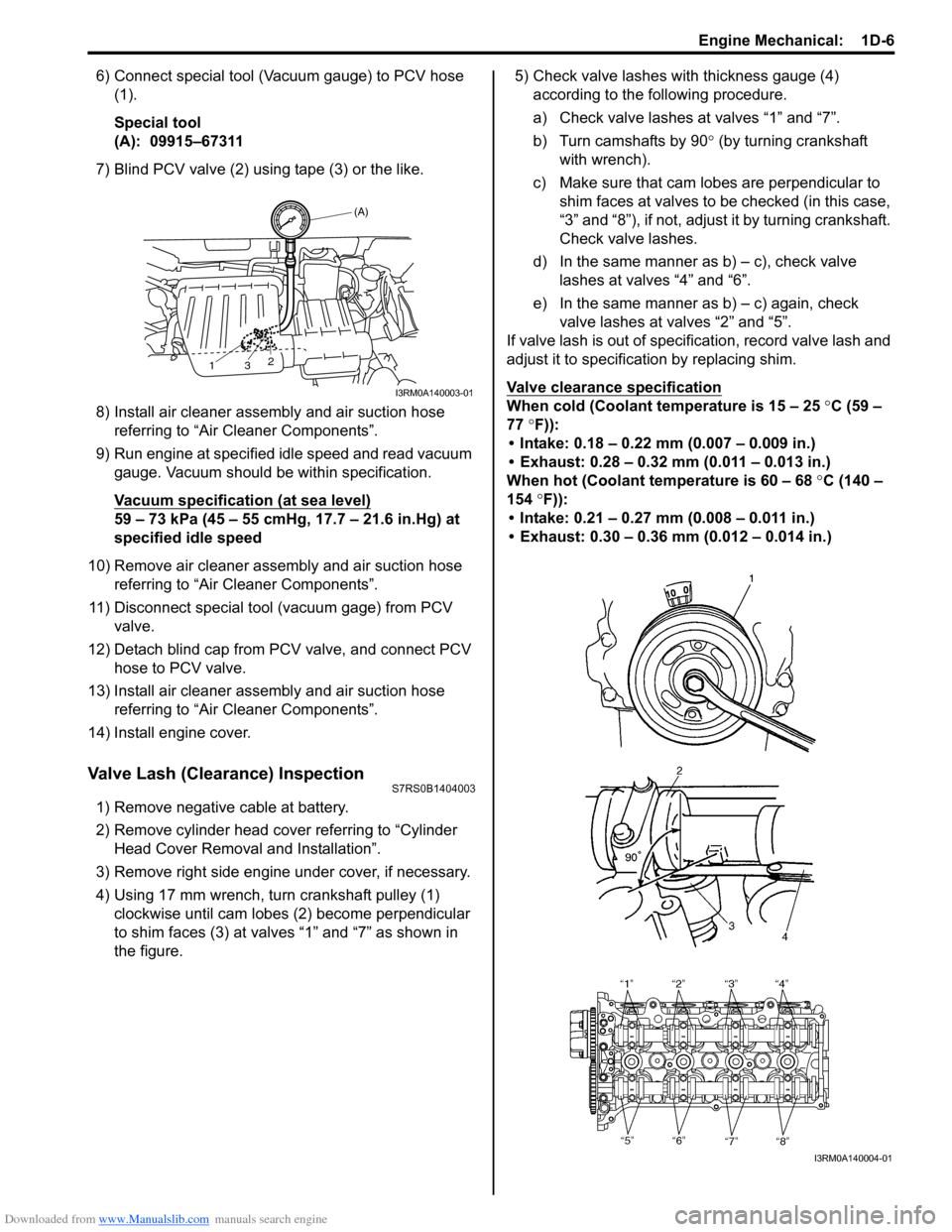
6) Connect special tool (Vacuum gauge) to PCV hose (1).
Special tool
(A): 09915–67311
7) Blind PCV valve (2) using tape (3) or the like.
8) Install air cleaner assembly and air suction hose referring to “Air Cleaner Components”.
9) Run engine at specified idle speed and read vacuum gauge. Vacuum should be within specification.
Vacuum specification (at sea level)
59 – 73 kPa (45 – 55 cmHg, 17.7 – 21.6 in.Hg) at
specified idle speed
10) Remove air cleaner assembly and air suction hose referring to “Air Cleaner Components”.
11) Disconnect special tool (vacuum gage) from PCV valve.
12) Detach blind cap from PCV valve, and connect PCV hose to PCV valve.
13) Install air cleaner assembly and air suction hose referring to “Air Cleaner Components”.
14) Install engine cover.
Valve Lash (Clearance) InspectionS7RS0B1404003
1) Remove negative cable at battery.
2) Remove cylinder head cover referring to “Cylinder Head Cover Removal and Installation”.
3) Remove right side engine under cover, if necessary.
4) Using 17 mm wrench, turn crankshaft pulley (1) clockwise until cam lobes (2) become perpendicular
to shim faces (3) at valves “1” and “7” as shown in
the figure. 5) Check valve lashes with thickness gauge (4)
according to the following procedure.
a) Check valve lashes at valves “1” and “7”.
b) Turn camshafts by 90 ° (by turning crankshaft
with wrench).
c) Make sure that cam lobes are perpendicular to shim faces at valves to be checked (in this case,
“3” and “8”), if not, adjust it by turning crankshaft.
Check valve lashes.
d) In the same manner as b) – c), check valve
lashes at valves “4” and “6”.
e) In the same manner as b) – c) again, check valve lashes at valves “2” and “5”.
If valve lash is out of specification, record valve lash and
adjust it to specification by replacing shim.
Valve clearance specification
When cold (Coolant te mperature is 15 – 25 °C (59 –
77 °F)):
• Intake: 0.18 – 0.22 mm (0.007 – 0.009 in.)
• Exhaust: 0.28 – 0.32 mm (0.011 – 0.013 in.)
When hot (Coolant temperature is 60 – 68 °C (140 –
154 °F)):
• Intake: 0.21 – 0.27 mm (0.008 – 0.011 in.)
• Exhaust: 0.30 – 0.36 mm (0.012 – 0.014 in.)
(A)
13 2
I3RM0A140003-01
I3RM0A140004-01
Page 302 of 1496

Downloaded from www.Manualslib.com manuals search engine 1D-17 Engine Mechanical:
Engine Assembly Removal and InstallationS7RS0B1406011
NOTE
After replacing electric throttle body
assembly, perform calibration of throttle
valve referring to “Electric Throttle Body
System Calibration in Section 1C”.
Removal1) Relieve fuel pressure according to “Fuel Pressure Relief Procedure in Section 1G”.
2) Disconnect negative and pos itive cable at battery.
3) Remove battery and tray.
4) Remove engine hood after disconnecting windshield washer hose.
5) Remove right and left side engine under covers.
6) Remove A/C compressor belt by referring to “Compressor Drive Belt Remo val and Installation in
Section 7B” or “Compressor Drive Belt Removal and
Installation in Section 7B”.
7) Drain engine oil, transaxle oil and coolant.
8) Remove cowl top plate referring to “Cowl Top Components in Section 9K”.
9) Remove air cleaner assembly referring to “Air Cleaner Components”.
10) With hose connected, detach A/C compressor from its bracket (A/C model) referring to “Compressor
Assembly Removal and Installation in Section 7B” or
“Compressor Assembly Removal and Installation in
Section 7B”.
CAUTION!
Suspend removed A/C compressor at a place
where no damage will be caused during
removal and installation of engine assembly.
11) Remove intake manifold rear stiffener (1) from intake manifold and cylinder block. 12) Disconnect the following electric wires:
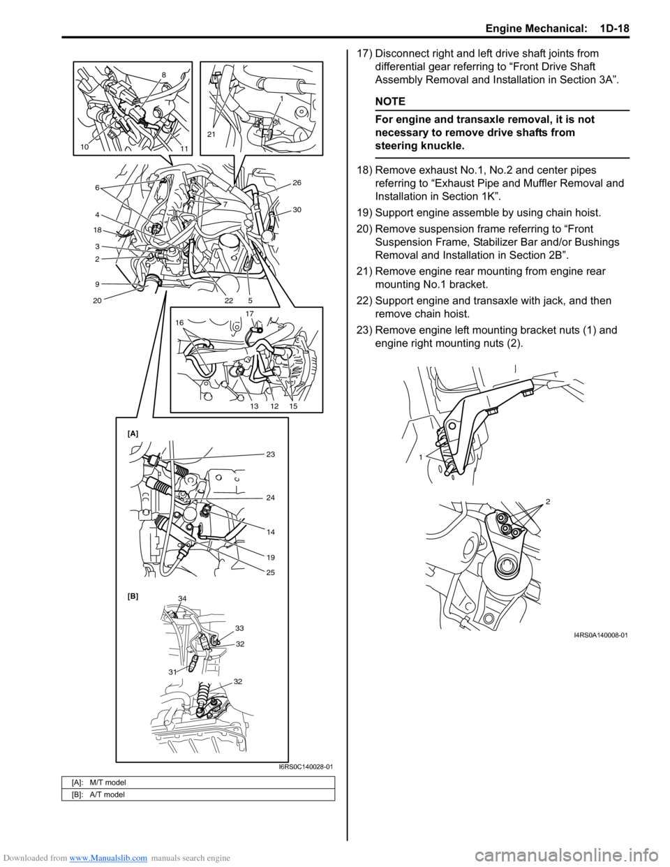
• MAP sensor (1)
• ECT sensor (2)
•EGR valve (3)
• CMP sensor (4)
• Electric throttle body assembly (5)
• Ignition coil assembly (6)
• Injectors (7)
• Heated oxygen sensor No. 2 (8) and No. 1 (9)
• Oil control valve (10)
• Engine oil pressure switch (11)
• CKP sensor (12)
• Knock sensor (13)
• Back up light switch (14)
• Generator (15)
• Starting motor (16)
• Ground terminal (17) from intake manifold
• Battery ground terminal (18) from exhaust manifold
• Battery ground cable (19) from transaxle
• Magnet clutch switch of A/C compressor (A/C model)
• Each wire harness clamps
• Output shaft speed sensor (VSS) (34) (A/T model)
• Solenoid valve (33) (A/T model)
• Transmission range sensor (32) (A/T model)
• Input shaft speed sensor (31) (A/T model)
13) Remove fuse box from its bracket.
14) Disconnect the following cables: • Gear select control cable (23) (M/T model)
• Gear shift control cable (24) (M/T model)
• A/T select cable (A/T model)
15) Disconnect the following hoses: • Brake booster hose (26) from intake manifold
• Radiator inlet and outlet hoses (20) from each pipe
• Heater inlet and outlet hoses (21) from each pipe
• Fuel feed hoses (22) from fuel feed pipe
• EVAP canister purge valve hose (30) from purge pipe
• A/T fluid cooler hoses (A/T model)
16) With hose connected, detach clutch operating cylinder (25). (M/T model)
CAUTION!
Suspend removed clutch operating cylinder
at a place where no damage will be caused
during removal and installation of engine
assembly.
1
I6RS0B141014-01
Page 303 of 1496
Downloaded from www.Manualslib.com manuals search engine Engine Mechanical: 1D-18
17) Disconnect right and left drive shaft joints from differential gear referring to “Front Drive Shaft
Assembly Removal and Installation in Section 3A”.
NOTE
For engine and transaxle removal, it is not
necessary to remove drive shafts from
steering knuckle.
18) Remove exhaust No.1, No.2 and center pipes referring to “Exhaust Pipe and Muffler Removal and
Installation in Section 1K”.
19) Support engine assemble by using chain hoist.
20) Remove suspension frame referring to “Front Suspension Frame, Stabiliz er Bar and/or Bushings
Removal and Installati on in Section 2B”.
21) Remove engine rear mounting from engine rear mounting No.1 bracket.
22) Support engine and transaxle with jack, and then remove chain hoist.
23) Remove engine left mounting bracket nuts (1) and engine right mounting nuts (2).
[A]: M/T model
[B]: A/T model
7
26
30
5
4
22
3
2
20
6
9
18
8
11
10
21 1
16
17
151213
[B]
23
24
14
25 19
34
33
32
32
31
[A]
I6RS0C140028-01
1
2
I4RS0A140008-01
Page 304 of 1496
Downloaded from www.Manualslib.com manuals search engine 1D-19 Engine Mechanical:
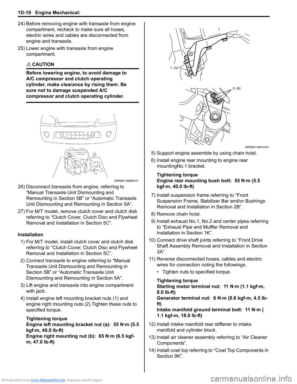
24) Before removing engine with transaxle from engine compartment, recheck to make sure all hoses,
electric wires and cables are disconnected from
engine and transaxle.
25) Lower engine with transaxle from engine compartment.
CAUTION!
Before lowering engine, to avoid damage to
A/C compressor and clutch operating
cylinder, make clearance by rising them. Be
sure not to damage suspended A/C
compressor and clutch operating cylinder.
26) Disconnect transaxle from engine, referring to “Manual Transaxle Unit Dismounting and
Remounting in Section 5B” or “Automatic Transaxle
Unit Dismounting and Re mounting in Section 5A”.
27) For M/T model, remove clutch cover and clutch disk referring to “Clutch Cover, Clutch Disc and Flywheel
Removal and Installa tion in Section 5C”.
Installation 1) For M/T model, install clutch cover and clutch disk referring to “Clutch Cover, Clutch Disc and Flywheel
Removal and Installa tion in Section 5C”.
2) Connect transaxle to engine referring to “Manual Transaxle Unit Dismounting and Remounting in
Section 5B” or “Automatic Transaxle Unit
Dismounting and Remounting in Section 5A”.
3) Lift engine and transaxle into engine compartment with jack.
4) Install engine left mounting bracket nuts (1) and engine right mounting nuts (2).Tighten these nuts to
specified torque.
Tightening torque
Engine left mounting bracket nut (a): 55 N·m (5.5
kgf-m, 40.0 lb-ft)
Engine right mounting nut (b): 65 N·m (6.5 kgf-
m, 47.0 lb-ft) 5) Support engine assemble by using chain hoist.
6) Install engine rear mounting to engine rear
mountingNo.1 bracket.
Tightening torque
Engine rear mounting bush bolt: 55 N·m (5.5
kgf-m, 40.0 lb-ft)
7) Install suspension frame referring to “Front Suspension Frame, Stabiliz er Bar and/or Bushings
Removal and Installati on in Section 2B”.
8) Remove chain hoist.
9) Install exhaust No.1, No.2 and center pipes referring to “Exhaust Pipe and Muffler Removal and
Installation in Section 1K”.
10) Connect drive shaft joints referring to “Front Drive Shaft Assembly Removal and Installation in Section
3A”.
11) Reverse disconnected hoses, cables and electric wires for connection noting the followings.
• Tighten nuts to specified torque.
Tightening torque
Starting motor terminal nut: 11 N·m (1.1 kgf-m,
8.0 lb-ft)
Generator terminal nut: 6 N·m (0.6 kgf-m, 4.5 lb-
ft)
Intake manifold ground terminal bolt: 11 N·m (
1.1 kgf-m, 18.0 lb-ft)
12) Install intake manifold rear stiffener to intake
manifold and cylinder block.
13) Install air cleaner assembly referring to “Air Cleaner Components”.
14) Install cowl top referring to “Cowl Top Components in
Section 9K”.
I4RS0A140009-01
1, (a)
2, (b)
I4RS0A140010-01