headlight leveling switch SUZUKI SWIFT 2008 2.G Service Workshop Manual
[x] Cancel search | Manufacturer: SUZUKI, Model Year: 2008, Model line: SWIFT, Model: SUZUKI SWIFT 2008 2.GPages: 1496, PDF Size: 34.44 MB
Page 947 of 1496
Downloaded from www.Manualslib.com manuals search engine Heater and Ventilation: 7A-11
Side Ventilation Louver Removal and
Installation
S7RS0B7106015
Driver side ventilation louver
Removal1) Disconnect negative (–) cable from battery.
2) Disable air bag system referring to “Disabling Air Bag System in Section 8B”.
3) Remove steering column hol e cover from instrument
panel.
4) Remove combination meter cluster panel from instrument panel, and then disconnect connectors
from front fog lamp switch, illumination cancel switch
and headlight leveling switch (if equipped) of
combination meter cluster panel.
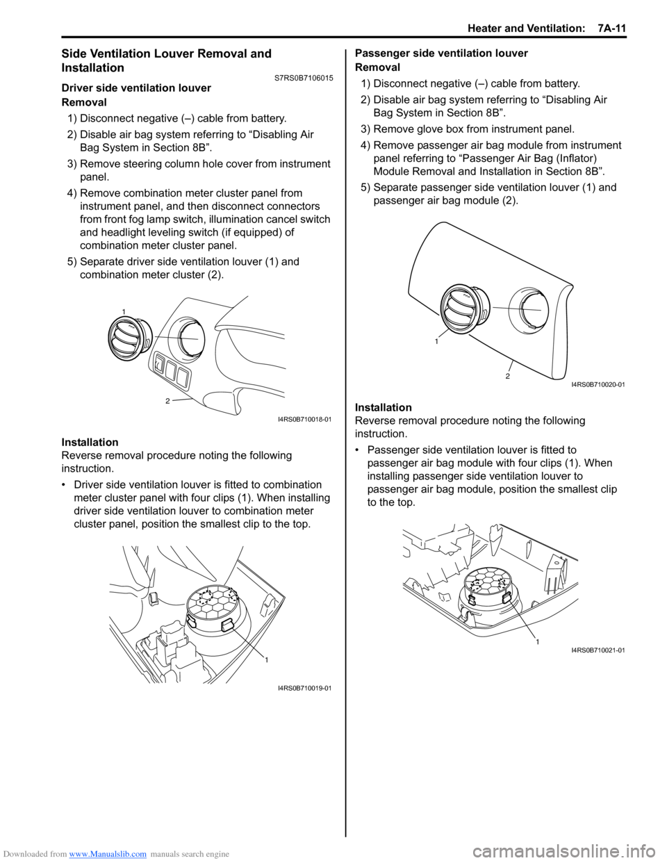
5) Separate driver side ventilation louver (1) and combination meter cluster (2).
Installation
Reverse removal procedure noting the following
instruction.
• Driver side ventilation louver is fitted to combination meter cluster panel with four clips (1). When installing
driver side ventilation louv er to combination meter
cluster panel, position the smallest clip to the top. Passenger side ventilation louver
Removal
1) Disconnect negative (–) cable from battery.
2) Disable air bag system referring to “Disabling Air Bag System in Section 8B”.
3) Remove glove box from instrument panel.
4) Remove passenger air bag module from instrument panel referring to “Passenger Air Bag (Inflator)
Module Removal and Installation in Section 8B”.
5) Separate passenger side ventilation louver (1) and passenger air bag module (2).
Installation
Reverse removal procedure noting the following
instruction.
• Passenger side ventilation louver is fitted to passenger air bag module with four clips (1). When
installing passenger side ventilation louver to
passenger air bag module, position the smallest clip
to the top.
2
1
I4RS0B710018-01
1
I4RS0B710019-01
2
1
I4RS0B710020-01
1I4RS0B710021-01
Page 1168 of 1496

Downloaded from www.Manualslib.com manuals search engine 9-ii Table of Contents
List of Connectors ........................................... 9A-103
C Connector .................................................... 9A-103
D Connector (M16A engine) ........................... 9A-104
E Connector .................................................... 9A-104
G Connector .................................................... 9A-106
J Connector ..................................................... 9A-108
K Connector .................................................... 9A-109
L Connector..................................................... 9A-109
M Connector (SPORT model) ......................... 9A-111
O Connector .................................................... 9A-111
R Connector .................................................... 9A-111
Lighting Systems .................................... 9B-1
Component Location ........... ................................9B-1
Lighting System Component s Location............... 9B-1
Interior Light System Location............................. 9B-2
Diagnostic Information and Procedures ............ 9B-2 Headlight Symptom Diagnosis ............................ 9B-2
Headlight Leveling System Symptom Diagnosis (If Equipped) ..................................... 9B-2
Turn Signal and Hazard Warning Light Symptom Diagnosis .......................................... 9B-3
Clearance, Tail and License Plate Light Symptom Diagnosis .......................................... 9B-3
Back-Up Light Symptom Diagnosis..................... 9B-4
Brake Light Symptom Diagnosis ......................... 9B-4
Front Fog Light Symptom Diagnosis (If Equipped) .......................................................... 9B-4
Interior Light Symptom Diagnosis ....................... 9B-5
Repair Instructions ..............................................9B-5 Headlight Housing Removal and Installation ...... 9B-5
Headlight Bulb Replacemen t............................... 9B-6
Headlight Aiming Adjustment with Screen .......... 9B-6
Headlight Switch (in Lighting Switch) Removal and Installation ................................... 9B-8
Headlight Switch (in Lighting Switch) Inspection .......................................................... 9B-8
Hazard Warning Switch Removal and Installation ......................................................... 9B-8
Hazard Warning Switch Inspection ..................... 9B-9
Brake Light Switch Inspection ............................. 9B-9
Turn Signal Light Switch (in Lighting Switch) Removal and Installation ................................... 9B-9
Turn Signal Light Switch (in Lighting Switch) Inspection .......................................................... 9B-9
Turn Signal and Hazard Warning Relay Removal and Installation ................................... 9B-9
Turn Signal and Hazard Warning Relay Inspection ........................................................ 9B-10
License Light Removal and Installation............. 9B-10
Front Fog Light Removal and Installation (If Equipped) ........................................................ 9B-11
Front Fog Light Bulb Replacement (If Equipped) ........................................................ 9B-11
Front Fog Light Switch Inspection (If Equipped) ........................................................ 9B-11
Front Fog Light Relay Inspection (If Equipped) ........................................................ 9B-11
Front Fog Light Aiming Adjustment with Screen (If Equipped) ....................................... 9B-12 Headlight Leveling Switch Inspection (If
Equipped) ........................................................ 9B-13
Headlight Leveling Actuator Inspection (If Equipped) ........................................................ 9B-13
Instrumentation / Driver Info. / Horn ...... 9C-1
Precautions ...........................................................9C-1 Precautions in Diagnosing Troubles for Combination Meter ............................................9C-1
General Description .............................................9C-1 CAN Communication System Description...........9C-1
Auto Volume Co ntrol System Description (If
Equipped) ..........................................................9C-3
Schematic and Routing Diagram ........................9C-4 Combination Meter Circuit Diagram ....................9C-4
Component Location ............ ...............................9C-6
Audio System Component Location ....................9C-6
Diagnostic Information and Procedures ............9C-6 Speedometer and VSS Symp tom Diagnosis ......9C-6
Tachometer Symptom Diagnosis ........................9C-6
Engine Coolant Temperature (ECT) Meter Symptom Diagnosis ..........................................9C-7
Fuel Meter Symptom Diagnosis ..........................9C-7
Low Fuel Warning Light Symptom Diagnosis .....9C-7
Oil Pressure Warning Light Symptom Diagnosis ..........................................................9C-8
Brake and Parking Brake Warning Light Symptom Diagnosis ..........................................9C-8
Seat Belt Reminder Light Symptom Diagnosis (If Equipped)......................................................9C-8
A/T Shift Position Indicator Symptom Diagnosis (A/T Model).......................................9C-9
Charge Warning Light Sy mptom Diagnosis ........9C-9
Main Beam (High Beam) Indicator Symptom Diagnosis ..........................................................9C-9
Warning Buzzer Circuit Sy mptom Diagnosis ....9C-10
Cigarette Lighter Symptom Diagnosis (If Equipped) ........................................................9C-10
Horn Symptom Diagnosis .................................9C-10
Information Display Symptom Diagnosis (If Equipped) ........................................................9C-11
Clock Symptom Diagnosis (If Equipped)...........9C-12
Audio System Symptom Diagnosis (If Equipped) ........................................................9C-12
Remote Audio Control Switch Symptom Diagnosis (If Equipped) ...................................9C-13
Navigation Symptom Diagnosis (If Equipped)...9C-14
Repair Instructions ............ ................................9C-14
Ignition Switch Removal and Installation...........9C-14
Ignition Switch Inspection..................................9C-14
Combination Meter Removal and Installation ...9C-15
Fuel Level Sensor Removal and Installation .....9C-15
Fuel Level Sensor Inspection ............................9C-15
Oil Pressure Switch Remova l and Installation ..9C-15
Oil Pressure Switch Inspec tion .........................9C-16
Engine Coolant Temperature (ECT) Sensor Inspection ........................................................9C-16
Brake Fluid Level Switch Inspection .................9C-16
Parking Brake Switch Inspec tion.......................9C-16
Page 1174 of 1496
Downloaded from www.Manualslib.com manuals search engine 9A-3 Wiring Systems:
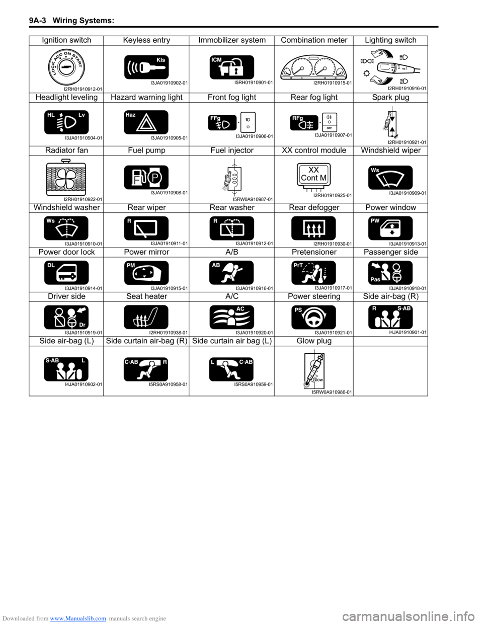
Ignition switch Keyless entry Immobilizer system Combination meter Lighting switch
Headlight leveling Hazard warning light Front fog light Rear fog light Spark plug Radiator fan Fuel pumpFuel injectorXX control module Windshield wiper
Windshield washer Rear wiper Rear washer Rear defogger Power window
Power door lock Power mirror A/BPretensioner Passenger side
Driver side Seat heater A/CPower steering Side air-bag (R)
Side air-bag (L) Side curtain air-bag (R) Side curtain air bag (L) Glow plug
I2RH01910912-01I3JA01910902-01I5RH01910901-01I2RH01910915-01I2RH01910916-01
I3JA01910904-01I3JA01910905-01I3JA01910906-01I3JA01910907-01I2RH01910921-01
I2RH01910922-01I3JA01910908-01I5RW0A910987-01
XX
Cont M
I2RH01910925-01I3JA01910909-01
I3JA01910910-01I3JA01910911-01I3JA01910912-01I2RH01910930-01I3JA01910913-01
I3JA01910914-01I3JA01910915-01I3JA01910916-01I3JA01910917-01I3JA01910918-01
I3JA01910919-01I2RH01910938-01I3JA01910920-01I3JA01910921-01I4JA01910901-01
I4JA01910902-01I5RS0A910958-01I5RS0A910959-01
I5RW0A910986-01
Page 1186 of 1496
Downloaded from www.Manualslib.com manuals search engine 9A-15 Wiring Systems:
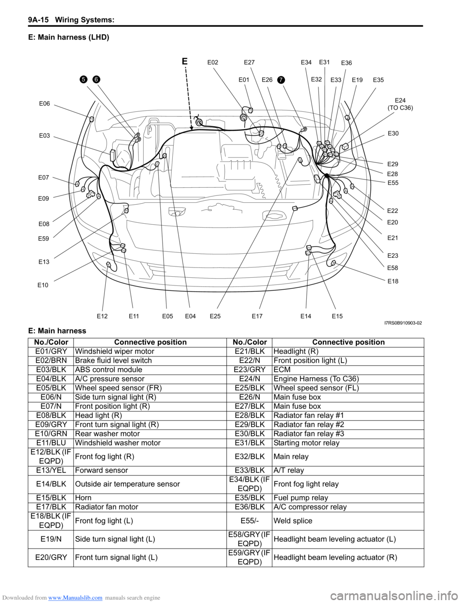
E: Main harness (LHD)
E: Main harness
56
E06E12
E
E03
E07
E09
E59E08
E13
E10
E11E05 E04
E01
E02E197
E34
E31
E32
E24
(TO C36)
E33
E36
E35
E30
E29
E28
E20
E21
E22
E58
E27
E26
E23
E25E17
E18
E14 E15
E55
I7RS0B910903-02
No./Color
Connective position No./ColorConnective position
E01/GRY Windshield wiper motor E21/BLK Headlight (R)
E02/BRN Brake fluid level switch E22/N Front position light (L)
E03/BLK ABS control module E23/GRY ECM
E04/BLK A/C pressure sensor E24/N Engine Harness (To C36)
E05/BLK Wheel speed sensor (FR) E25/BLK Wheel speed sensor (FL)
E06/N Side turn signal light (R) E26/N Main fuse box
E07/N Front position light (R) E27/BLK Main fuse box
E08/BLK Head light (R) E28/BLK Radiator fan relay #1
E09/GRY Front turn signal light (R) E29/BLK Radiator fan relay #2
E10/GRN Rear washer motor E30/BLK Radiator fan relay #3
E11/BLU Windshield washer motor E31/BLK Starting motor relay
E12/BLK (IF EQPD) Front fog light (R)
E32/BLK Main relay
E13/YEL Forward sensor E33/BLK A/T relay
E14/BLK Outside air temperature sensor E34/BLK (IF
EQPD) Front fog light relay
E15/BLK Horn E35/BLK Fuel pump relay
E17/BLK Radiator fan motor E36/BLK A/C compressor relay
E18/BLK (IF
EQPD) Front fog light (L)
E55/- Weld splice
E19/N Side turn signal light (L) E58/GRY (IF
EQPD) Headlight beam leveling actuator (L)
E20/GRY Front turn signal light (L) E59/GRY (IF
EQPD) Headlight beam leveling actuator (R)
Page 1190 of 1496
Downloaded from www.Manualslib.com manuals search engine 9A-19 Wiring Systems:
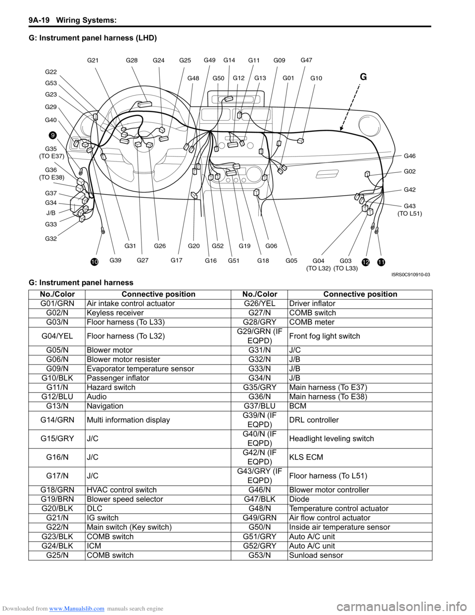
G: Instrument panel harness (LHD)
G: Instrument panel harness
J/B
9
10
G33
G32 G34 G35
(TO E37)
G36
(TO E38)
G29
G40
G23
G53
G22 G21
G28
G20G52
G27G39 G26
G31
1112G03
(TO L33)G04
(TO L32)
G46
G02
G42
G43
(TO L51)
G10
G47G11
G13G01
G14
G49
G50G48
G25
G24
G12
G17
G16G51G19
G18
G06
G05
G
G09
G37
I5RS0C910910-03
No./Color Connective position No./ColorConnective position
G01/GRN Air intake control ac tuatorG26/YEL Driver inflator
G02/N Keyless receiver G27/N COMB switch
G03/N Floor harness (To L33) G28/GRY COMB meter
G04/YEL Floor harness (To L32) G29/GRN (IF
EQPD) Front fog light switch
G05/N Blower motor G31/N J/C
G06/N Blower motor resister G32/N J/B
G09/N Evaporator temperature sensor G33/N J/B
G10/BLK Passenger inflator G34/N J/B
G11/N Hazard switch G35/GRY Main harness (To E37)
G12/BLU Audio G36/N Main harness (To E38)
G13/N Navigation G37/BLU BCM
G14/GRN Multi information display G39/N (IF
EQPD) DRL controller
G15/GRY J/C G40/N (IF
EQPD) Headlight leveling switch
G16/N J/C G42/N (IF
EQPD) KLS ECM
G17/N J/C G43/GRY (IF
EQPD) Floor harness (To L51)
G18/GRN HVAC control switch G46/N Blower motor controller
G19/BRN Blower speed selector G47/BLK Diode
G20/BLK DLC G48/N Temperature control actuator
G21/N IG switch G49/GRN Air flow control actuator
G22/N Main switch (Key switch) G50/N Inside air temperature sensor
G23/BLK COMB switch G51/GRY Auto A/C unit
G24/BLK ICM G52/GRY Auto A/C unit
G25/N COMB switch G53/N Sunload sensor
Page 1206 of 1496
Downloaded from www.Manualslib.com manuals search engine 9A-35 Wiring Systems:
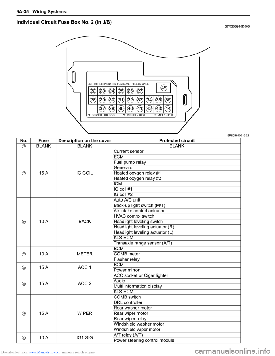
Individual Circuit Fuse Box No. 2 (In J/B)S7RS0B910D006
22
28
23
29
37
24
30
38
25
31
39
26
32
40
27
33
41
34
42
35
43
36
44
45USE THE DESINGNATED FUSES AND RELAYS ONLY.
*1: DEICER / RR FOG *2: DIESEL / HID L *3: MTA / HID R
I5RS0B910919-02
No. Fuse Description on the coverProtected circuit
BLANK BLANK BLANK
15 A IG COILCurrent sensor
ECM
Fuel pump relay
Generator
Heated oxygen relay #1
Heated oxygen relay #2
ICM
IG coil #1
IG coil #2
10 A BACKAuto A/C unit
Back-up light switch (M/T)
Air intake control actuator
HVAC control switch
Headlight leveling switch
Headlight leveling actuator (R)
Headlight leveling actuator (L)
KLS ECM
Transaxle range sensor (A/T)
10 A METERBCM
COMB meter
Flasher relay
15 A ACC 1BCM
Power mirror
15 A ACC 2ACC socket or Cigar lighter
Audio
Multi information display
KLS ECM
15 A WIPERCOMB switch
DRL controller
Rear washer motor
Rear wiper motor
Rear wiper relay
Windshield washer motor
Windshield wiper motor
10 A IG1 SIGA/T relay (A/T)
Power steering control module
Page 1258 of 1496
Downloaded from www.Manualslib.com manuals search engine 9A-87 Wiring Systems:
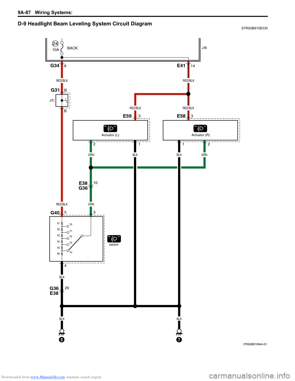
D-9 Headlight Beam Leveling System Circuit DiagramS7RS0B910E030
10A
RED/BLK
GRN
GRN
RED/BLKRED/BLK
GRN
BLK
BLKBLK
switch
24BACK
RED/BLKRED/BLK
E59
G343E583
1
8E4114
12
G40 E38
G3653
4 10
G36
E3820 2
BLKBLK
Actuator (L)
Actuator (R)
R1
P0
P1
P2
P3
P4
R2
R3
R4
R5
R6
J/B
57
B
B
J/C
G31
I7RS0B910944-01
Page 1283 of 1496
Downloaded from www.Manualslib.com manuals search engine Lighting Systems: 9B-1
Body, Cab and Accessories
Lighting Systems
Component Location
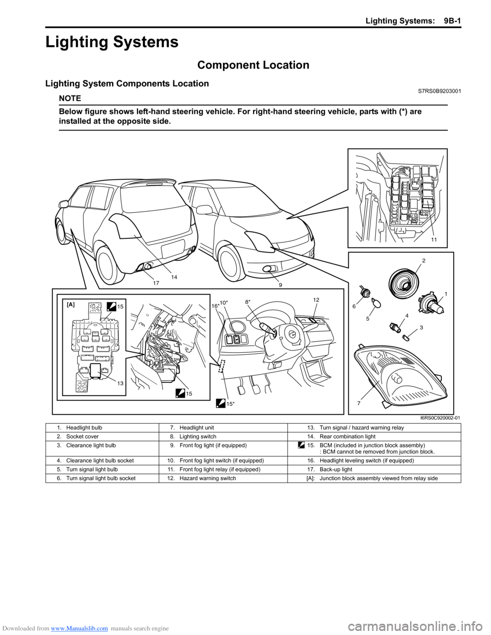
Lighting System Components LocationS7RS0B9203001
NOTE
Below figure shows left-hand steering vehicle. For right-hand steering vehicle, parts with (*) are
installed at the opposite side.
2
1
3
4
6
14
5
7
11
9
15
[A]
1515*
10*
8* 12
13
16*
17
I6RS0C920002-01
1. Headlight bulb 7. Headlight unit 13. Turn signal / hazard warning relay
2. Socket cover 8. Lighting switch 14. Rear combination light
3. Clearance light bulb 9. Front fog light (if equipped)15. BCM (included in junction block assembly)
: BCM cannot be removed from junction block.
4. Clearance light bulb socket 10. Front fog light switch (if equipped) 16. Headlight leveling switch (if equipped)
5. Turn signal light bulb 11. Front fog light relay (if equipped) 17. Back-up light
6. Turn signal light bulb socket 12. Hazard warning switch [A]: Junction block assembly viewed from relay side
Page 1284 of 1496
Downloaded from www.Manualslib.com manuals search engine 9B-2 Lighting Systems:
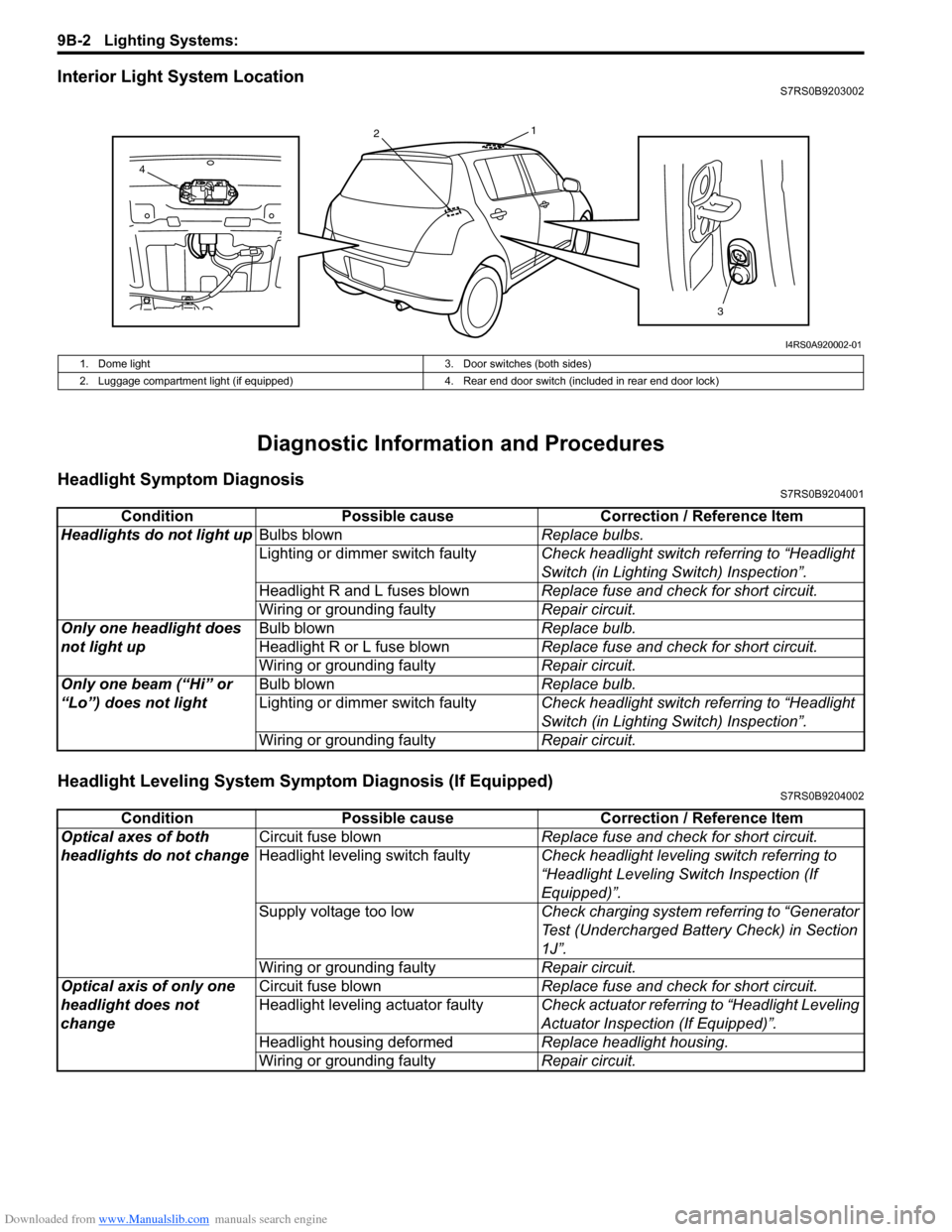
Interior Light System LocationS7RS0B9203002
Diagnostic Information and Procedures
Headlight Symptom DiagnosisS7RS0B9204001
Headlight Leveling System Symptom Diagnosis (If Equipped)S7RS0B9204002
13
2
4
I4RS0A920002-01
1. Dome light 3. Door switches (both sides)
2. Luggage compartment light (if equipped) 4. Rear end door switch (included in rear end door lock)
ConditionPossible cause Correction / Reference Item
Headlights do not light up Bulbs blown Replace bulbs.
Lighting or dimmer switch faulty Check headlight switch referring to “Headlight
Switch (in Lighting Switch) Inspection”.
Headlight R and L fuses blown Replace fuse and check for short circuit.
Wiring or grounding faulty Repair circuit.
Only one headlight does
not light up Bulb blown
Replace bulb.
Headlight R or L fuse blown Replace fuse and check for short circuit.
Wiring or grounding faulty Repair circuit.
Only one beam (“Hi” or
“Lo”) does not light Bulb blown
Replace bulb.
Lighting or dimmer switch faulty Check headlight switch referring to “Headlight
Switch (in Lighting Switch) Inspection”.
Wiring or grounding faulty Repair circuit.
ConditionPossible cause Correction / Reference Item
Optical axes of both
headlights do not change Circuit fuse blown
Replace fuse and check for short circuit.
Headlight leveling switch faulty Check headlight leveling switch referring to
“Headlight Leveling Switch Inspection (If
Equipped)”.
Supply voltage too low Check charging system referring to “Generator
Test (Undercharged Battery Check) in Section
1J”.
Wiring or grounding faulty Repair circuit.
Optical axis of only one
headlight does not
change Circuit fuse blown
Replace fuse and check for short circuit.
Headlight leveling actuator faulty Check actuator referring to “Headlight Leveling
Actuator Inspection (If Equipped)”.
Headlight housing deformed Replace headlight housing.
Wiring or grounding faulty Repair circuit.
Page 1288 of 1496
Downloaded from www.Manualslib.com manuals search engine 9B-6 Lighting Systems:
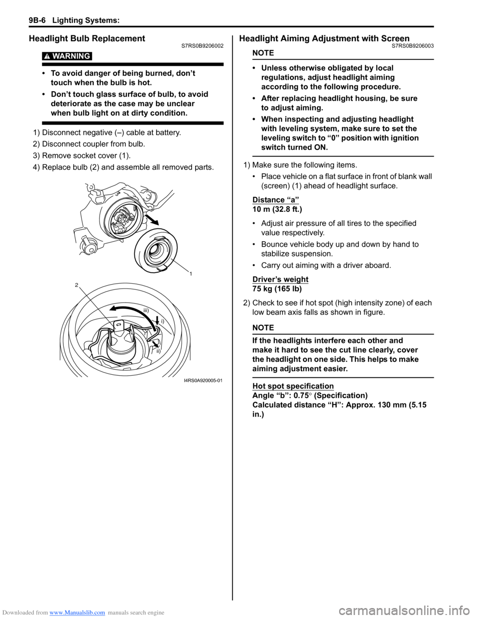
Headlight Bulb ReplacementS7RS0B9206002
WARNING!
• To avoid danger of being burned, don’t touch when the bulb is hot.
• Don’t touch glass surface of bulb, to avoid deteriorate as the case may be unclear
when bulb light on at dirty condition.
1) Disconnect negative (–) cable at battery.
2) Disconnect coupler from bulb.
3) Remove socket cover (1).
4) Replace bulb (2) and assemble all removed parts.
Headlight Aiming Adjustment with ScreenS7RS0B9206003
NOTE
• Unless otherwise obligated by local regulations, adjust headlight aiming
according to the following procedure.
• After replacing headlight housing, be sure to adjust aiming.
• When inspecting and adjusting headlight with leveling system, make sure to set the
leveling switch to “0 ” position with ignition
switch turned ON.
1) Make sure the following items.
• Place vehicle on a flat surface in front of blank wall (screen) (1) ahead of headlight surface.
Distance “a”
10 m (32.8 ft.)
• Adjust air pressure of all tires to the specified value respectively.
• Bounce vehicle body up and down by hand to stabilize suspension.
• Carry out aiming with a driver aboard.
Driver’s weight
75 kg (165 lb)
2) Check to see if hot spot (high intensity zone) of each low beam axis falls as shown in figure.
NOTE
If the headlights interfere each other and
make it hard to see the cut line clearly, cover
the headlight on one side. This helps to make
aiming adjustment easier.
Hot spot specification
Angle “b”: 0.75 ° (Specification)
Calculated distance “H”: Approx. 130 mm (5.15
in.)
1
iii)
2
i)
ii)
I4RS0A920005-01