headlight tool SUZUKI SWIFT 2008 2.G Service Workshop Manual
[x] Cancel search | Manufacturer: SUZUKI, Model Year: 2008, Model line: SWIFT, Model: SUZUKI SWIFT 2008 2.GPages: 1496, PDF Size: 34.44 MB
Page 228 of 1496
Downloaded from www.Manualslib.com manuals search engine 1A-178 Engine General Information and Diagnosis:
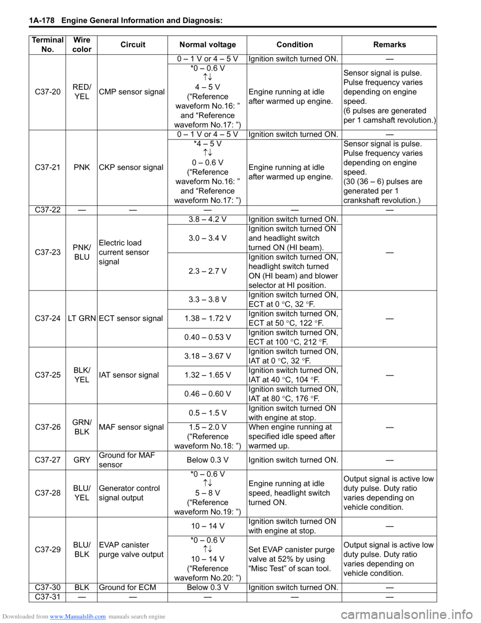
C37-20RED/
YEL CMP sensor signal 0 – 1 V or 4 – 5 V Ignition switch turned ON. —
*0 – 0.6 V↑↓
4 – 5 V
(“Reference
waveform No.16: ” and “Reference
waveform No.17: ”) Engine running at idle
after warmed up engine.
Sensor signal is pulse.
Pulse frequency varies
depending on engine
speed.
(6 pulses are generated
per 1 camshaft revolution.)
C37-21 PNK CKP sensor signal 0 – 1 V or 4 – 5 V Ignition switch turned ON. —
*4 – 5 V↑↓
0 – 0.6 V
(“Reference
waveform No.16: ” and “Reference
waveform No.17: ”) Engine running at idle
after warmed up engine. Sensor signal is pulse.
Pulse frequency varies
depending on engine
speed.
(30 (36 – 6) pulses are
generated per 1
crankshaft revolution.)
C37-22 — — — — —
C37-23 PNK/
BLU Electric load
current sensor
signal 3.8 – 4.2 V Ignition switch turned ON.
—
3.0 – 3.4 V
Ignition switch turned ON
and headlight switch
turned ON (HI beam).
2.3 – 2.7 V Ignition switch turned ON,
headlight switch turned
ON (HI beam) and blower
selector at HI position.
C37-24 LT GRN ECT sensor signal 3.3 – 3.8 V
Ignition switch turned ON,
ECT at 0
°C, 32 °F.
—
1.38 – 1.72 V Ignition switch turned ON,
ECT at 50
°C, 122 °F.
0.40 – 0.53 V Ignition switch turned ON,
ECT at 100
°C, 212 °F.
C37-25 BLK/
YEL IAT sensor signal 3.18 – 3.67 V
Ignition switch turned ON,
IAT at 0
°C, 32 °F.
—
1.32 – 1.65 V Ignition switch turned ON,
IAT at 40
°C, 104 °F.
0.46 – 0.60 V Ignition switch turned ON,
IAT at 80
°C, 176 °F.
C37-26 GRN/
BLK MAF sensor signal 0.5 – 1.5 V
Ignition switch turned ON
with engine at stop.
—
1.5 – 2.0 V
(“Reference
waveform No.18: ”) Wh
en engine running at
specified idle speed after
warmed up.
C37-27 GRY Ground for MAF
sensor Below 0.3 V Ignition switch turned ON.
—
C37-28 BLU/
YEL Generator control
signal output *0 – 0.6 V
↑↓
5 – 8 V
(“Reference
waveform No.19: ”) Engine running at idle
speed, headlight switch
turned ON.
Output signal is active low
duty pulse. Duty ratio
varies depending on
vehicle condition.
C37-29 BLU/
BLK EVAP canister
purge valve output 10 – 14 V
Ignition switch turned ON
with engine at stop. —
*0 – 0.6 V ↑↓
10 – 14 V
(“Reference
waveform No.20: ”) Set EVAP canister purge
valve at 52% by using
“Misc Test” of scan tool.
Output signal is active low
duty pulse. Duty ratio
varies depending on
vehicle condition.
C37-30 BLK Ground for ECM Below 0.3 V Ignition switch turned ON. —
C37-31 — —— — —
Terminal
No. Wire
color Circuit Normal voltage
ConditionRemarks
Page 239 of 1496
Downloaded from www.Manualslib.com manuals search engine Engine General Information and Diagnosis: 1A-189
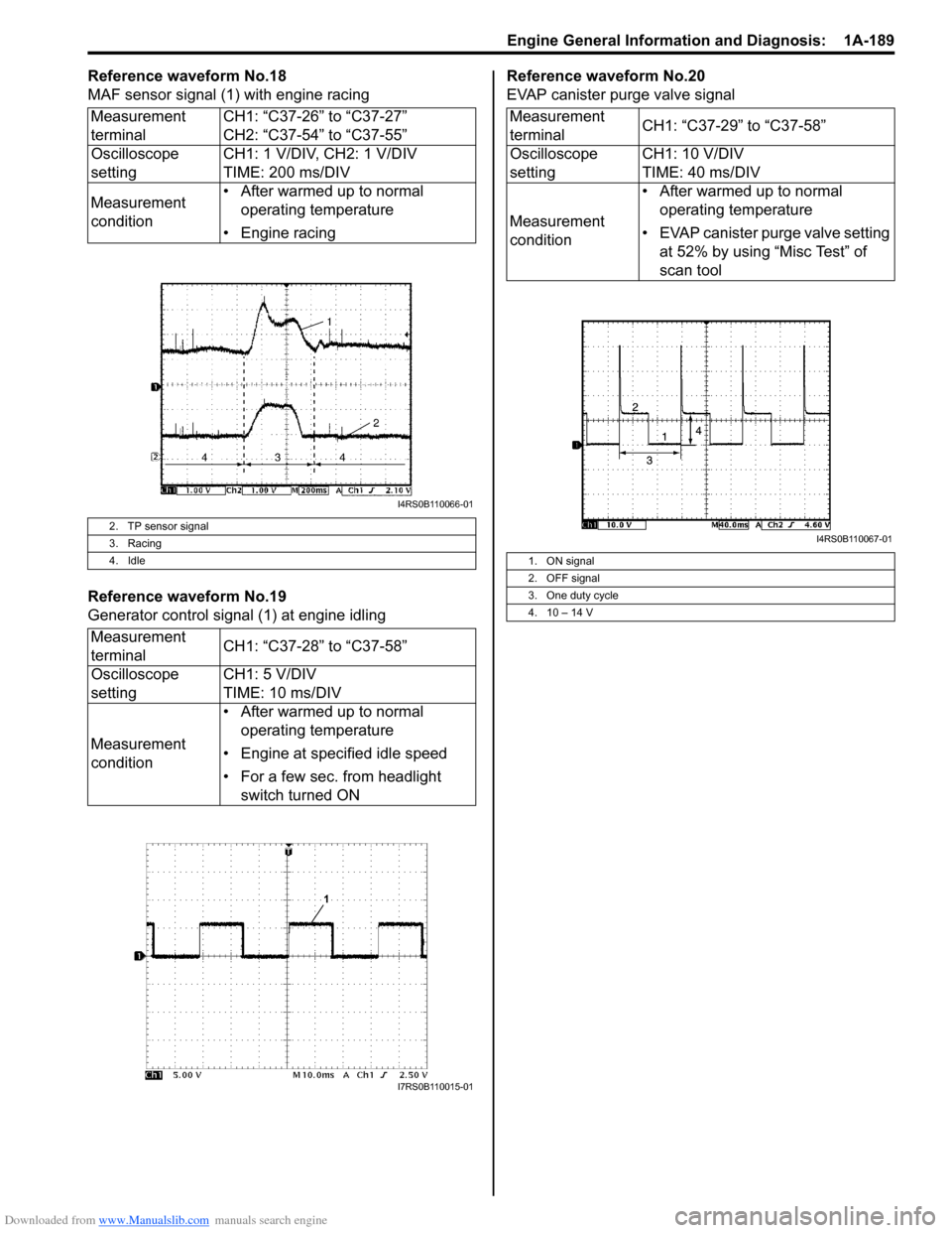
Reference waveform No.18
MAF sensor signal (1) with engine racing
Reference waveform No.19
Generator control signal (1) at engine idlingReference waveform No.20
EVAP canister purge valve signal
Measurement
terminal CH1: “C37-26” to “C37-27”
CH2: “C37-54” to “C37-55”
Oscilloscope
setting CH1: 1 V/DIV, CH2: 1 V/DIV
TIME: 200 ms/DIV
Measurement
condition • After warmed up to normal
operating temperature
• Engine racing
2. TP sensor signal
3. Racing
4. Idle
Measurement
terminal CH1: “C37-28” to “C37-58”
Oscilloscope
setting CH1: 5 V/DIV
TIME: 10 ms/DIV
Measurement
condition • After warmed up to normal
operating temperature
• Engine at specified idle speed
• For a few sec. from headlight switch turned ON
I4RS0B110066-01
I7RS0B110015-01
Measurement
terminal CH1: “C37-29” to “C37-58”
Oscilloscope
setting CH1: 10 V/DIV
TIME: 40 ms/DIV
Measurement
condition • After warmed up to normal
operating temperature
• EVAP canister purge valve setting at 52% by using “Misc Test” of
scan tool
1. ON signal
2. OFF signal
3. One duty cycle
4. 10 – 14 V
I4RS0B110067-01
Page 259 of 1496
Downloaded from www.Manualslib.com manuals search engine Engine General Information and Diagnosis: 1A-209
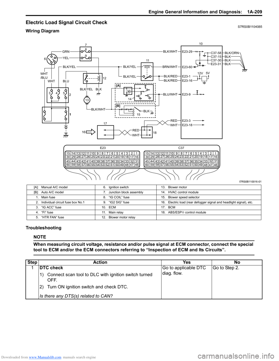
Electric Load Signal Circuit CheckS7RS0B1104085
Wiring Diagram
Troubleshooting
NOTE
When measuring circuit voltage, resistance and/or pulse signal at ECM connector, connect the special
tool to ECM and/or the ECM connectors referri ng to “Inspection of ECM and Its Circuits”.
BLK/WHT
BLK/RED
WHT
BRN/WHT
12V5V
11
BLK/YELBLK/YEL
BLK/YEL
BLKBLKBLK
BLK/ORN
10
18
17
BLU/WHT
15
WHTRED
43
YEL
5
13
BLK/WHT
BLKBLK/YEL
GRN
WHT
/BLU
BLU
16
2
6
7
12
8
9
BLK
WHT
RED
E23-29
E23-60
E23-1E23-16
E23-9
E23-3E23-18
C37-58C37-15
E23-31C37-30
BLK/RED
[A]
[B]
E23 C37
34
1819
567
10
11
17
20
47 46
495051
2122
52 16
25 9
24
14
29
5557 54 53
59
60 58 2
262728
15
30
56 4832 31
34353637
4042 39 38
44
45 43 41 331
1213
238
34
1819
567
10
11
17
20
47 46
495051
2122
52 16
25 9
24
14
29
5557 54 53
59
60 58 2
262728
15
30
56 4832 31
34353637
4042 39 38
44
45 43 41 331
12
13
238
1
14
I7RS0B110016-01
[A]: Manual A/C model
6. Ignition switch13. Blower motor
[B]: Auto A/C model 7. Junction block assembly14. HVAC control module
1. Main fuse 8. “IG COIL” fuse15. Blower speed selector
2. Individual circuit fuse box No.1 9. “IG2 SIG” fuse16. Electric load (rear defogger signal and headlight signal), etc.
3. “IG ACC” fuse 10. ECM17. BCM
4. “FI” fuse 11. Main relay18. ABS/ESP® control module
5. “HTR FAN” fuse 12. Blower motor relay
StepAction YesNo
1 DTC check
1) Connect scan tool to DLC with ignition switch turned
OFF.
2) Turn ON ignition switch and check DTC.
Is there any DTS(s) related to CAN? Go to applicable DTC
diag. flow.
Go to Step 2.
Page 260 of 1496
Downloaded from www.Manualslib.com manuals search engine 1A-210 Engine General Information and Diagnosis:
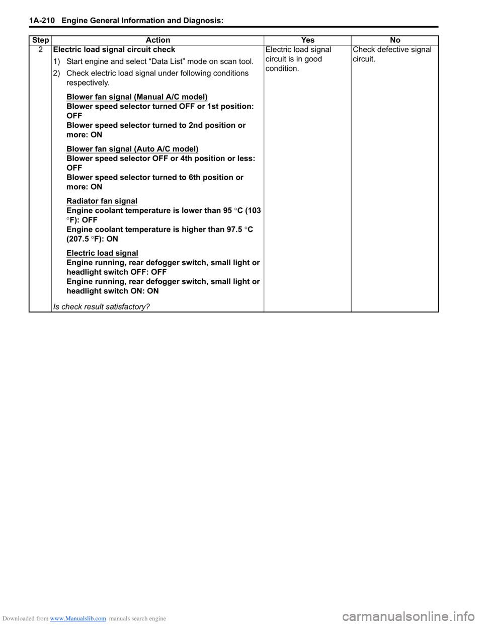
2Electric load signal circuit check
1) Start engine and select “Data List” mode on scan tool.
2) Check electric load signal under following conditions
respectively.
Blower fan signal (Manual A/C model)
Blower speed selector turned OFF or 1st position:
OFF
Blower speed selector turned to 2nd position or
more: ON
Blower fan signal (Auto A/C model)
Blower speed selector OFF or 4th position or less:
OFF
Blower speed selector turned to 6th position or
more: ON
Radiator fan signal
Engine coolant temperature is lower than 95 °C (103
° F): OFF
Engine coolant temperature is higher than 97.5 °C
(207.5 °F): ON
Electric load signal
Engine running, rear defogger switch, small light or
headlight switch OFF: OFF
Engine running, rear defogger switch, small light or
headlight switch ON: ON
Is check result satisfactory? Electric load signal
circuit is in good
condition.
Check defective signal
circuit.
Step Action Yes No
Page 284 of 1496
Downloaded from www.Manualslib.com manuals search engine 1C-12 Engine Electrical Devices:
MAF and IAT Sensor InspectionS7RS0B1306020
CAUTION!
Do not heat up MAF and IAT sensor more
than 100 °C (212 °F). Otherwise, MAF and IAT
sensor will be damaged.
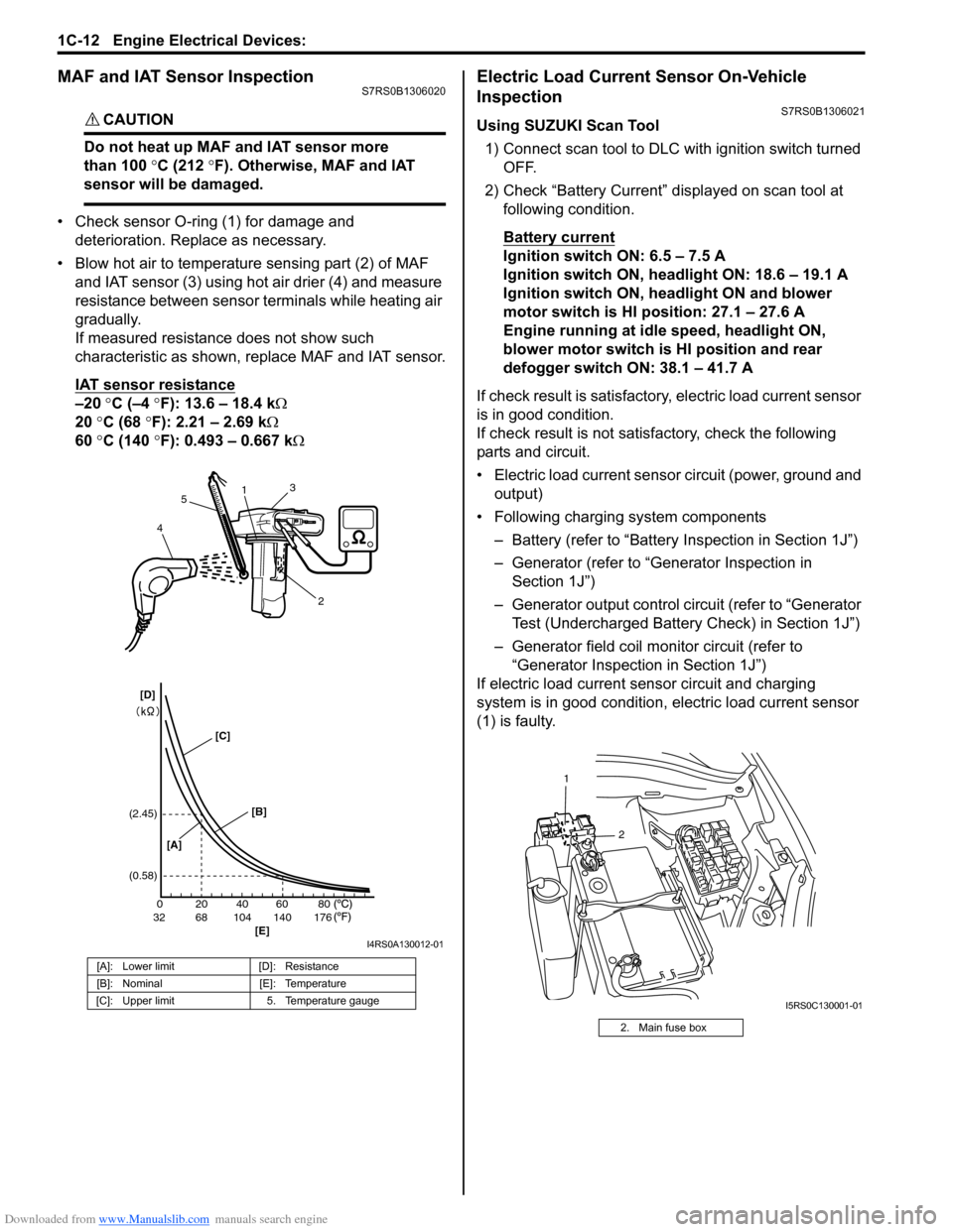
• Check sensor O-ring (1) for damage and deterioration. Replace as necessary.
• Blow hot air to temperature sensing part (2) of MAF and IAT sensor (3) using hot air drier (4) and measure
resistance between sensor terminals while heating air
gradually.
If measured resistance does not show such
characteristic as shown, replace MAF and IAT sensor.
IAT sensor resistance
–20 °C (–4 °F): 13.6 – 18.4 k Ω
20 °C (68 °F): 2.21 – 2.69 k Ω
60 °C (140 °F): 0.493 – 0.667 k Ω
Electric Load Current Sensor On-Vehicle
Inspection
S7RS0B1306021
Using SUZUKI Scan Tool
1) Connect scan tool to DLC with ignition switch turned OFF.
2) Check “Battery Current” displayed on scan tool at following condition.
Battery current
Ignition switch ON: 6.5 – 7.5 A
Ignition switch ON, headlight ON: 18.6 – 19.1 A
Ignition switch ON, headlight ON and blower
motor switch is HI position: 27.1 – 27.6 A
Engine running at idle speed, headlight ON,
blower motor switch is HI position and rear
defogger switch ON: 38.1 – 41.7 A
If check result is satisfactory, electric load current sensor
is in good condition.
If check result is not satisf actory, check the following
parts and circuit.
• Electric load current sensor circuit (power, ground and output)
• Following charging system components
– Battery (refer to “Battery Inspection in Section 1J”)
– Generator (refer to “Generator Inspection in Section 1J”)
– Generator output control ci rcuit (refer to “Generator
Test (Undercharged Battery Check) in Section 1J”)
– Generator field coil monitor circuit (refer to “Generator Inspection in Section 1J”)
If electric load current sensor circuit and charging
system is in good condition, electric load current sensor
(1) is faulty.
[A]: Lower limit [D]: Resistance
[B]: Nominal [E]: Temperature
[C]: Upper limit 5. Temperature gauge
200
6832104 140 17640 60 80
(2.45)
(0.58)
1
2
3
4 5
[A] [B]
[E]
[C]
[D]
I4RS0A130012-01
2. Main fuse box
2
1
I5RS0C130001-01
Page 1285 of 1496
Downloaded from www.Manualslib.com manuals search engine Lighting Systems: 9B-3
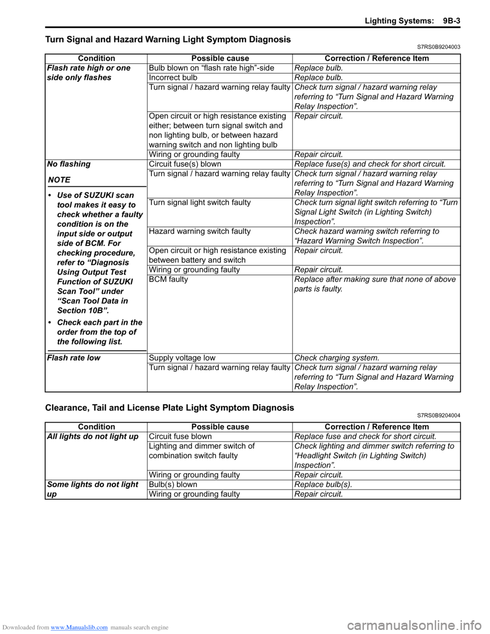
Turn Signal and Hazard Warning Light Symptom DiagnosisS7RS0B9204003
Clearance, Tail and License Plate Light Symptom DiagnosisS7RS0B9204004
ConditionPossible cause Correction / Reference Item
Flash rate high or one
side only flashes Bulb blown on “flash rate high”-side
Replace bulb.
Incorrect bulb Replace bulb.
Turn signal / hazard warning relay faulty Check turn signal / hazard warning relay
referring to “Turn Signal and Hazard Warning
Relay Inspection”.
Open circuit or high resistance existing
either; between turn signal switch and
non lighting bulb, or between hazard
warning switch and non lighting bulb Repair circuit.
Wiring or grounding faulty Repair circuit.
No flashing
NOTE
• Use of SUZUKI scan tool makes it easy to
check whether a faulty
condition is on the
input side or output
side of BCM. For
checking procedure,
refer to “Diagnosis
Using Output Test
Function of SUZUKI
Scan Tool” under
“Scan Tool Data in
Section 10B”.
• Check each part in the order from the top of
the following list.
Circuit fuse(s) blown Replace fuse(s) and check for short circuit.
Turn signal / hazard warning relay faulty Check turn signal / hazard warning relay
referring to “Turn Signal and Hazard Warning
Relay Inspection”.
Turn signal light switch faulty Check turn signal light switch referring to “Turn
Signal Light Switch (in Lighting Switch)
Inspection”.
Hazard warning switch faulty Check hazard warning switch referring to
“Hazard Warning Switch Inspection”.
Open circuit or high resistance existing
between battery and switch Repair circuit.
Wiring or grounding faulty Repair circuit.
BCM faulty Replace after making sure that none of above
parts is faulty.
Flash rate low Supply voltage low Check charging system.
Turn signal / hazard warning relay faulty Check turn signal / hazard warning relay
referring to “Turn Signal and Hazard Warning
Relay Inspection”.
ConditionPossible cause Correction / Reference Item
All lights do not light up Circuit fuse blown Replace fuse and check for short circuit.
Lighting and dimmer switch of
combination switch faulty Check lighting and dimmer switch referring to
“Headlight Switch (in Lighting Switch)
Inspection”.
Wiring or grounding faulty Repair circuit.
Some lights do not light
up Bulb(s) blown
Replace bulb(s).
Wiring or grounding faulty Repair circuit.
Page 1287 of 1496
Downloaded from www.Manualslib.com manuals search engine Lighting Systems: 9B-5
Interior Light Symptom DiagnosisS7RS0B9204008
NOTE
• Use of SUZUKI scan tool makes it easy to check whether a faulty condition is on the input side or
output side of BCM. For checking procedure, re fer to “Diagnosis Using Output Test Function of
SUZUKI Scan Tool” under “Scan Tool Data in Section 10B”.
• Check each part in the order from the top of the following list.
Repair Instructions
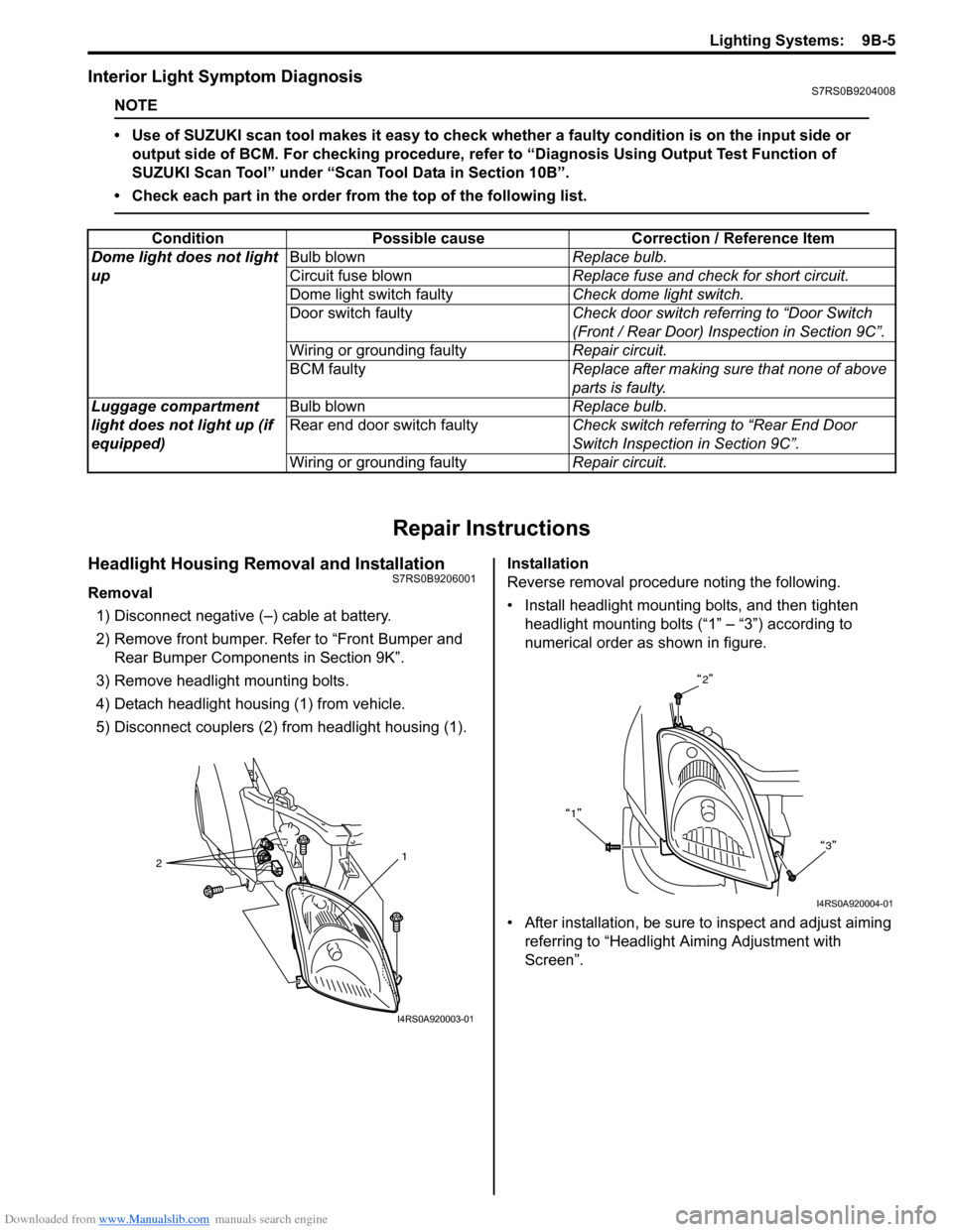
Headlight Housing Removal and InstallationS7RS0B9206001
Removal 1) Disconnect negative (–) cable at battery.
2) Remove front bumper. Refer to “Front Bumper and Rear Bumper Componen ts in Section 9K”.
3) Remove headlight mounting bolts.
4) Detach headlight housing (1) from vehicle.
5) Disconnect couplers (2) from headlight housing (1). Installation
Reverse removal procedure noting the following.
• Install headlight mounting bolts, and then tighten
headlight mounting bolts (“1” – “3”) according to
numerical order as shown in figure.
• After installation, be sure to inspect and adjust aiming referring to “Headlight Aiming Adjustment with
Screen”.
Condition Possible cause Correction / Reference Item
Dome light does not light
up Bulb blown
Replace bulb.
Circuit fuse blown Replace fuse and check for short circuit.
Dome light switch faulty Check dome light switch.
Door switch faulty Check door switch referring to “Door Switch
(Front / Rear Door) Inspection in Section 9C”.
Wiring or grounding faulty Repair circuit.
BCM faulty Replace after making sure that none of above
parts is faulty.
Luggage compartment
light does not light up (if
equipped) Bulb blown
Replace bulb.
Rear end door switch faulty Check switch referring to “Rear End Door
Switch Inspection in Section 9C”.
Wiring or grounding faulty Repair circuit.
2 1
I4RS0A920003-01
2
1 3
I4RS0A920004-01
Page 1305 of 1496
Downloaded from www.Manualslib.com manuals search engine Instrumentation / Driver Info. / Horn: 9C-10
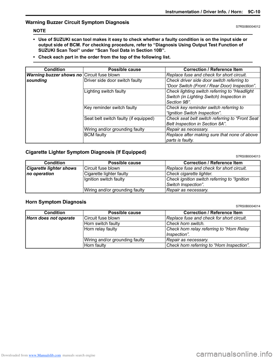
Warning Buzzer Circuit Symptom DiagnosisS7RS0B9304012
NOTE
• Use of SUZUKI scan tool makes it easy to check wh ether a faulty condition is on the input side or
output side of BCM. For checking procedure, re fer to “Diagnosis Using Output Test Function of
SUZUKI Scan Tool” under “Scan Tool Data in Section 10B”.
• Check each part in the order from the top of the following list.
Cigarette Lighter Symptom Diagnosis (If Equipped)S7RS0B9304013
Horn Symptom DiagnosisS7RS0B9304014
Condition Possible cause Correction / Reference Item
Warning buzzer shows no
sounding Circuit fuse blown
Replace fuse and check for short circuit.
Driver side door switch faulty Check driver side door switch referring to
“Door Switch (Front / Rear Door) Inspection”.
Lighting switch faulty Check lighting switch referring to “Headlight
Switch (in Lighting Switch) Inspection in
Section 9B”.
Key reminder switch faulty Check key reminder switch referring to
“Ignition Switch Inspection”.
Seat belt switch faulty (if equipped) Check seat belt switch referring to “Front Seat
Belt Inspection in Section 8A”.
Wiring and/or grounding faulty Repair as necessary.
BCM faulty Replace after making sure that none of above
parts is faulty.
ConditionPossible cause Correction / Reference Item
Cigarette lighter shows
no operation Circuit fuse blown
Replace fuse and check for short circuit.
Cigarette lighter faulty Check cigarette lighter.
Ignition switch faulty Check ignition switch referring to “Ignition
Switch Inspection”.
Wiring and/or grounding faulty Repair as necessary.
ConditionPossible cause Correction / Reference Item
Horn does not operate Circuit fuse blown Replace fuse and check for short circuit.
Horn switch faulty Check horn switch.
Horn relay faulty Check horn relay referring to “Horn Relay
Inspection”.
Wiring and/or grounding faulty Repair as necessary.
Horn faulty Check horn referring to “Horn Inspection”.
Page 1418 of 1496
Downloaded from www.Manualslib.com manuals search engine 10B-15 Body Electrical Control System:
Without Using SUZUKI Scan Tool1) Turn ignition switch to OFF position.
2) Perform following Steps a) to d) within 10 seconds af ter ignition switch is turned ON and engine stops.
a) Turn headlight switch to “SMALL” position.
b) Turn headlight switch to “OFF” position.
c) Repeat Steps a) and b) 2 times.
d) Press and release driver side door switch 3 times.
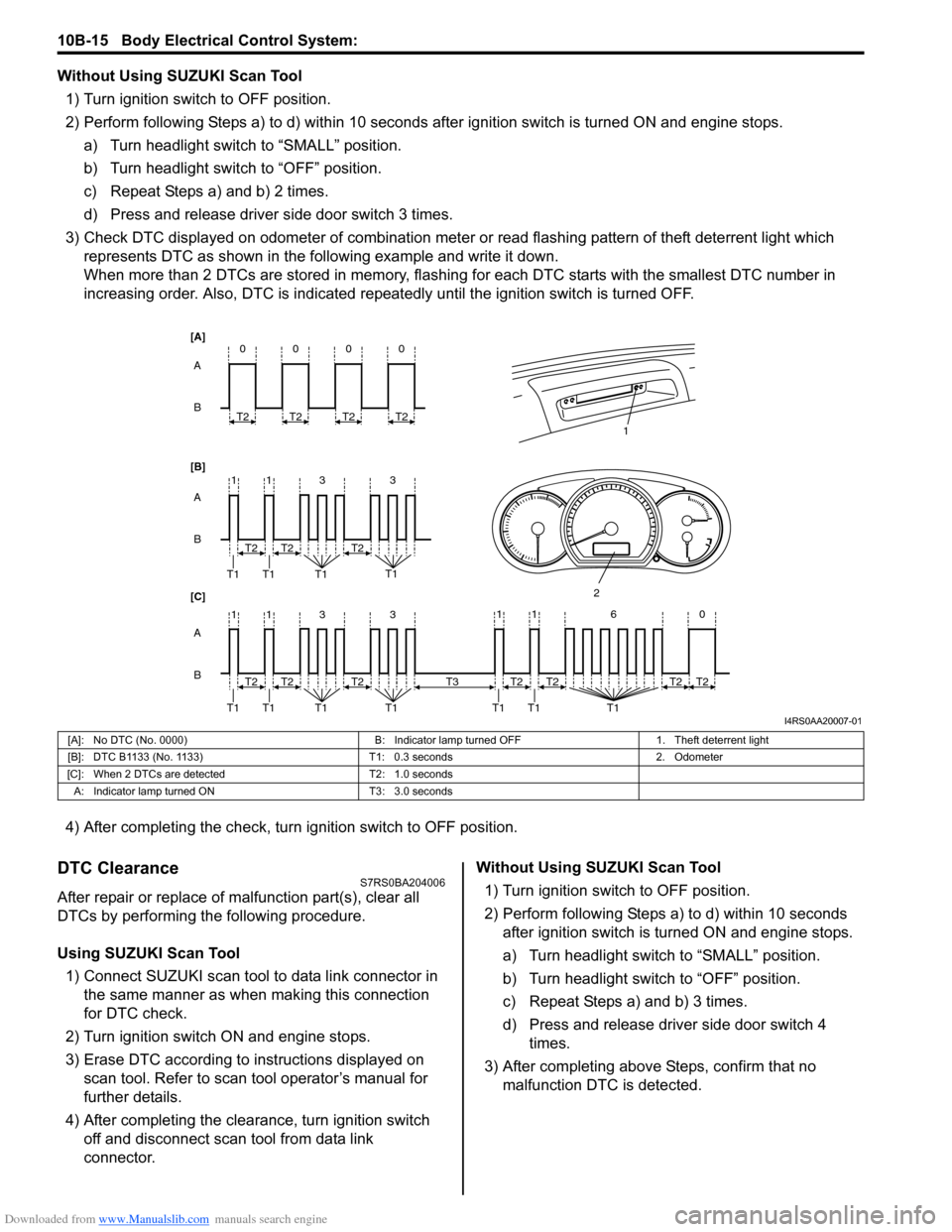
3) Check DTC displayed on odometer of combination meter or read flashing pattern of theft deterrent light which
represents DTC as shown in the following example and write it down.
When more than 2 DTCs are stored in memory, flashing for each DTC starts with the smallest DTC number in
increasing order. Also, DTC is indicated repeatedly until the ignition switch is turned OFF.
4) After completing the check, turn ignition switch to OFF position.
DTC ClearanceS7RS0BA204006
After repair or replace of malfunction part(s), clear all
DTCs by performing the following procedure.
Using SUZUKI Scan Tool 1) Connect SUZUKI scan tool to data link connector in the same manner as when making this connection
for DTC check.
2) Turn ignition switch ON and engine stops.
3) Erase DTC according to instructions displayed on scan tool. Refer to scan tool operator’s manual for
further details.
4) After completing the clear ance, turn ignition switch
off and disconnect scan tool from data link
connector. Without Using SUZUKI Scan Tool
1) Turn ignition switch to OFF position.
2) Perform following Steps a) to d) within 10 seconds after ignition switch is turned ON and engine stops.
a) Turn headlight switch to “SMALL” position.
b) Turn headlight switch to “OFF” position.
c) Repeat Steps a) and b) 3 times.
d) Press and release driver side door switch 4 times.
3) After completing above Steps, confirm that no malfunction DTC is detected.
B A
[B] [A]
[C]
B A B A
3
113
3
113
T2
T1 T1 T1 T1
1
2
T2T2
T2
T1 T1 T1 T1T2T2
0
T2
0
T2
0
T2
0
T2
11 6 0
T1 T1 T1
T2
T3T2T2T2
I4RS0AA20007-01
[A]: No DTC (No. 0000) B: Indicator lamp turned OFF1. Theft deterrent light
[B]: DTC B1133 (No. 1133) T1: 0.3 seconds2. Odometer
[C]: When 2 DTCs are detected T2: 1.0 seconds
A: Indicator lamp tur ned ON T3: 3.0 seconds