parking light SUZUKI SWIFT 2008 2.G Service Workshop Manual
[x] Cancel search | Manufacturer: SUZUKI, Model Year: 2008, Model line: SWIFT, Model: SUZUKI SWIFT 2008 2.GPages: 1496, PDF Size: 34.44 MB
Page 4 of 1496

Downloaded from www.Manualslib.com manuals search engine 00
0
1
2
3
4
5
6
7
8
9
10
11
Vo l u m e 1
Precautions............................................................... 00-iPrecautions ............................................................ 00-1
General Information ................ ................................... 0-i
General Information ............................................... 0A-1
Maintenance and Lubricatio n ................................. 0B-1
Engine ......................................................................... 1-i Precautions .............................................................. 1-1
Engine General Information and Diagnosis ........... 1A-1
Aux. Emission Control Devices .............................. 1B-1
Engine Electrical Devices....................................... 1C-1
Engine Mechanical ................................................. 1D-1
Engine Lubrication System .................................... 1E-1
Engine Cooling System .......................................... 1F-1
Fuel System ...........................................................1G-1
Ignition System....................................................... 1H-1
Starting System ....................................................... 1I-1
Charging System.....................................................1J-1
Exhaust System ..................................................... 1K-1
Suspension ................................................................. 2-i Precautions .............................................................. 2-1
Suspension General Diagnosis .............................. 2A-1
Front Suspension ................................................... 2B-1
Rear Suspension................ .................................... 2C-1
Wheels and Tires ................................................... 2D-1
Driveline / Axle ........................................................... 3-i Precautions .............................................................. 3-1
Drive Shaft / Axle ................................................... 3A-1
Brakes ......................................................................... 4-i Precautions .............................................................. 4-1
Brake Control System and Diagnosis .................... 4A-1
Front Brakes........................................................... 4B-1
Rear Brakes ........................................................... 4C-1
Parking Brake......................................................... 4D-1
ABS ........................................................................ 4E-1
Electronic Stability Program ................................... 4F-1
Vo l u m e 2
Precautions ............................................................... 00-iPrecautions ............................................................ 00-1
Transmission / Transaxle .... ...................................... 5-i
Precautions .............................................................. 5-1
Automatic Transmission/Transaxle ........................ 5A-1
Manual Transmission/Transaxle ............................ 5B-1
Clutch .....................................................................5C-1
Steering ....................................................................... 6-i Precautions .............................................................. 6-1
Steering General Diagnosis ................................... 6A-1
Steering Wheel and Column .................................. 6B-1
Power Assisted Steering System ...........................6C-1
HVAC ........................................................................... 7-i Precautions .............................................................. 7-1
Heater and Ventilation............................................ 7A-1
Air Conditioning System ......................................... 7B-1
Restraint ...................................................................... 8-i Precautions .............................................................. 8-1
Seat Belts ............................................................... 8A-1
Air Bag System ...................................................... 8B-1
Body, Cab and Accessories .... .................................. 9-i
Precautions .............................................................. 9-1
Wiring Systems ...................................................... 9A-1
Lighting Systems .................................................... 9B-1
Instrumentation / Driver Info. / Horn .......................9C-1
Wipers / Washers ...................................................9D-1
Glass / Windows / Mirrors ...................................... 9E-1
Security and Locks ................................................. 9F-1
Seats ..................................................................... 9G-1
Interior Trim ............................................................9H-1
Hood / Fenders / Doors .......................................... 9J-1
Body Structure ....................................................... 9K-1
Paint / Coatings ...................................................... 9L-1
Exterior Trim .......................................................... 9M-1
Control Systems ....................................................... 10-i Precautions ............................................................ 10-1
Body Electrical Control Sy stem ............................ 10B-1
Immobilizer Control System .................................10C-1
Keyless Start System ........................................... 10E-1
TABLE OF CONTENTS
Page 43 of 1496
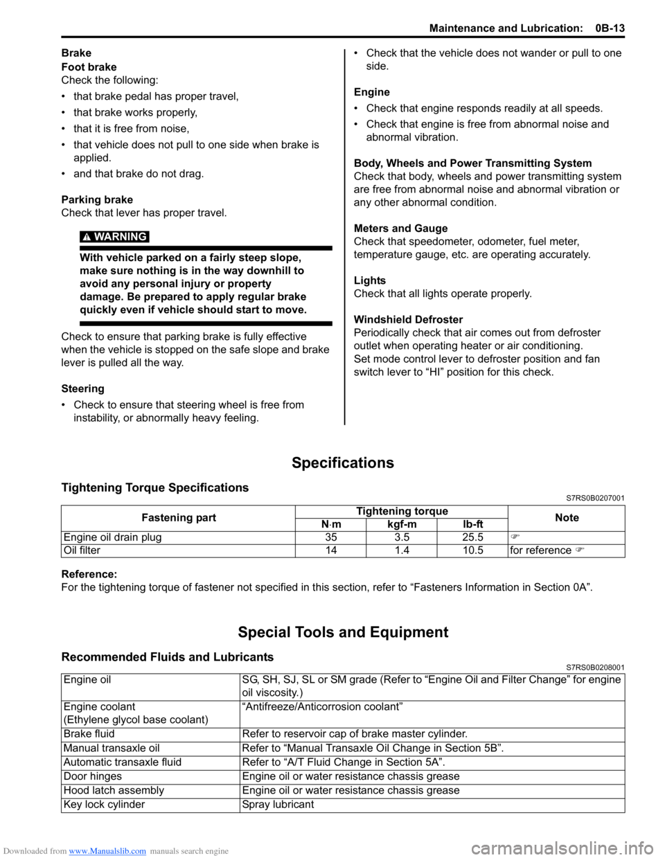
Downloaded from www.Manualslib.com manuals search engine Maintenance and Lubrication: 0B-13
Brake
Foot brake
Check the following:
• that brake pedal has proper travel,
• that brake works properly,
• that it is free from noise,
• that vehicle does not pull to one side when brake is applied.
• and that brake do not drag.
Parking brake
Check that lever has proper travel.
WARNING!
With vehicle parked on a fairly steep slope,
make sure nothing is in the way downhill to
avoid any personal injury or property
damage. Be prepared to apply regular brake
quickly even if vehicle should start to move.
Check to ensure that parking brake is fully effective
when the vehicle is stopped on the safe slope and brake
lever is pulled all the way.
Steering
• Check to ensure that steering wheel is free from instability, or abnormally heavy feeling. • Check that the vehicle does not wander or pull to one
side.
Engine
• Check that engine responds readily at all speeds.
• Check that engine is free from abnormal noise and abnormal vibration.
Body, Wheels and Power Transmitting System
Check that body, wheels and power transmitting system
are free from abnormal noise and abnormal vibration or
any other abnormal condition.
Meters and Gauge
Check that speedometer, odometer, fuel meter,
temperature gauge, etc. are operating accurately.
Lights
Check that all lights operate properly.
Windshield Defroster
Periodically check that ai r comes out from defroster
outlet when operating heater or air conditioning.
Set mode control lever to defroster position and fan
switch lever to “HI” position for this check.
Specifications
Tightening Torque SpecificationsS7RS0B0207001
Reference:
For the tightening torque of fastener not specified in this section, refer to “Fasteners Information in Section 0A”.
Special Tools and Equipment
Recommended Fluids and LubricantsS7RS0B0208001
Fastening part Tightening torque
Note
N ⋅mkgf-mlb-ft
Engine oil drain plug 35 3.5 25.5 �)
Oil filter 14 1.4 10.5 for reference �)
Engine oilSG, SH, SJ, SL or SM grade (Refer to “Engine Oil and Filter Change” for engine
oil viscosity.)
Engine coolant
(Ethylene glycol base coolant) “Antifreeze/Antico
rrosion coolant”
Brake fluid Refer to reservoir cap of brake master cylinder.
Manual transaxle oil Refer to “Manual Transaxle Oil Change in Section 5B”.
Automatic transaxle fluid Refer to “A/T Fluid Change in Section 5A”.
Door hinges Engine oil or water resistance chassis grease
Hood latch assembly Engine oil or water resistance chassis grease
Key lock cylinder Spray lubricant
Page 83 of 1496
Downloaded from www.Manualslib.com manuals search engine Engine General Information and Diagnosis: 1A-33
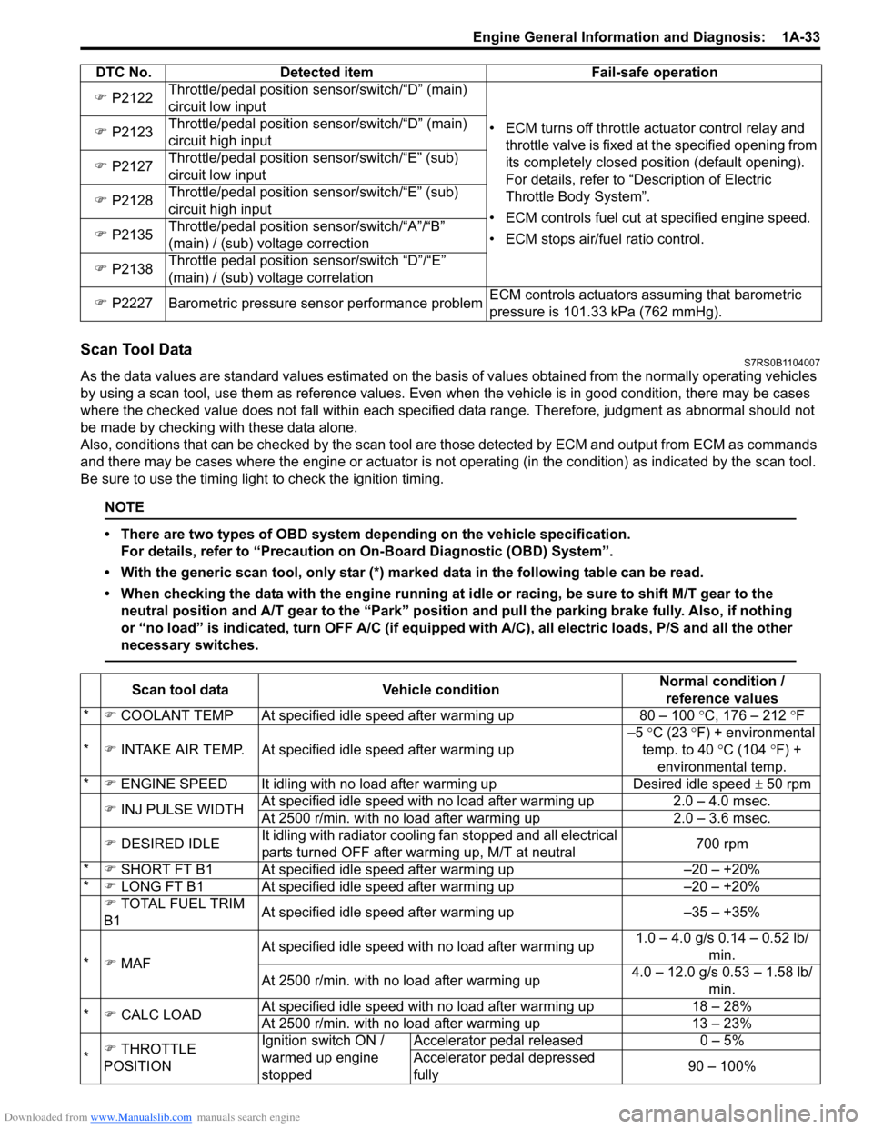
Scan Tool DataS7RS0B1104007
As the data values are standard values estimated on the basis of values obtained from the normally operating vehicles
by using a scan tool, use them as re ference values. Even when the vehicle is in good condition, there may be cases
where the checked value does not fall within each specified data range. Therefore, judgment as abnormal should not
be made by checking with these data alone.
Also, conditions that can be checked by the scan tool are those detected by ECM and output from ECM as commands
and there may be cases where the engine or actuator is not operating (in the condition) as indicated by the scan tool.
Be sure to use the timing light to check the ignition timing.
NOTE
• There are two types of OBD system depending on the vehicle specification.
For details, refer to “Precaution on On-Board Diagnostic (OBD) System”.
• With the generic scan tool, only star (*) marked data in the following table can be read.
• When checking the data with the engine running at idle or racing, be sure to shift M/T gear to the neutral position and A/T gear to the “Park” position and pull the parking brake fully. Also, if nothing
or “no load” is indicated, turn O FF A/C (if equipped with A/C), all electric loads, P/S and all the other
necessary switches.
�) P2122 Throttle/pedal position sensor/switch/“D” (main)
circuit low input
• ECM turns off throttle actuator control relay and throttle valve is fixed at the specified opening from
its completely closed position (default opening).
For details, refer to “Description of Electric
Throttle Body System”.
• ECM controls fuel cut at specified engine speed.
• ECM stops air/fuel ratio control.
�)
P2123 Throttle/pedal position sensor/switch/“D” (main)
circuit high input
�) P2127 Throttle/pedal position sensor/switch/“E” (sub)
circuit low input
�) P2128 Throttle/pedal position sensor/switch/“E” (sub)
circuit high input
�) P2135 Throttle/pedal position sensor/switch/“A”/“B”
(main) / (sub) voltage correction
�) P2138 Throttle pedal position sensor/switch “D”/“E”
(main) / (sub) voltage correlation
�) P2227 Barometric pressure sensor performance problem ECM controls actuators assuming that barometric
pressure is 101.33 kPa (762 mmHg).
DTC No. Detected item Fail-safe operation
Scan tool data
Vehicle condition Normal condition /
reference values
* �) COOLANT TEMP At specified idle speed after warming up 80 – 100 °C, 176 – 212 °F
* �) INTAKE AIR TEMP. At specifie d idle speed after warming up –5
°C (23 °F) + environmental
temp. to 40 °C (104 °F) +
environmental temp.
* �) ENGINE SPEED It idling with no load after warming upDesired idle speed ± 50 rpm
�) INJ PULSE WIDTH At specified idle speed with no load after warming up
2.0 – 4.0 msec.
At 2500 r/min. with no load after warming up 2.0 – 3.6 msec.
�) DESIRED IDLE It idling with radiator cooling fan stopped and all electrical
parts turned OFF after warming up, M/T at neutral 700 rpm
* �) SHORT FT B1 At specified idle speed after warming up –20 – +20%
* �) LONG FT B1 At specified idle speed after warming up –20 – +20%
�) TOTAL FUEL TRIM
B1 At specified idle speed after warming up
–35 – +35%
* �) MAF At specified idle speed wit
h no load after warming up 1.0 – 4.0 g/s 0.14 – 0.52 lb/
min.
At 2500 r/min. with no load after warming up 4.0 – 12.0 g/s 0.53 – 1.58 lb/
min.
* �) CALC LOAD At specified idle speed with no load after warming up
18 – 28%
At 2500 r/min. with no load after warming up 13 – 23%
* �)
THROTTLE
POSITION Ignition switch ON /
warmed up engine
stoppedAccelerator pedal released
0 – 5%
Accelerator pedal depressed
fully 90 – 100%
Page 266 of 1496
Downloaded from www.Manualslib.com manuals search engine 1A-216 Engine General Information and Diagnosis:
Repair Instructions
Idle Speed and IAC Throttle Valve Opening
Inspection
S7RS0B1106001
Before idle speed check, make sure of the following.
• Lead wires and hoses of electronic fuel injection and engine and emission control systems are connected
securely.
• Valve lash is checked according to maintenance schedule.
• Ignition timing is within specification.
• All accessories (wipers, heater, lights, A/C, etc.) are out of service.
• Air cleaner has been properly installed and is in good condition.
• No abnormal air drawn in from air intake system.
After all items are confirmed, check idle speed and IAC
duty as follows.
NOTE
Before starting engine, place transmission
gear shift lever in “Neutral” (shift selector
lever to “P” range for A/T vehicle), and set
parking brake and block drive wheels.
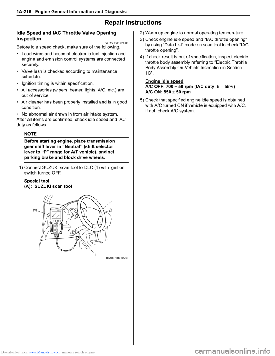
1) Connect SUZUKI scan tool to DLC (1) with ignition
switch turned OFF.
Special tool
(A): SUZUKI scan tool 2) Warm up engine to normal operating temperature.
3) Check engine idle speed and “IAC throttle opening”
by using “Data List” mode on scan tool to check “IAC
throttle opening”.
4) If check result is out of sp ecification, inspect electric
throttle body assembly referring to “Electric Throttle
Body Assembly On-Vehicle Inspection in Section
1C”.
Engine idle speed
A/C OFF: 700 ± 50 rpm (IAC duty: 5 – 55%)
A/C ON: 850 ± 50 rpm
5) Check that specified engine idle speed is obtained with A/C turned ON if vehi cle is equipped with A/C.
If not, check A/C system.
(A)
1
I4RS0B110093-01
Page 289 of 1496
Downloaded from www.Manualslib.com manuals search engine Engine Mechanical: 1D-4
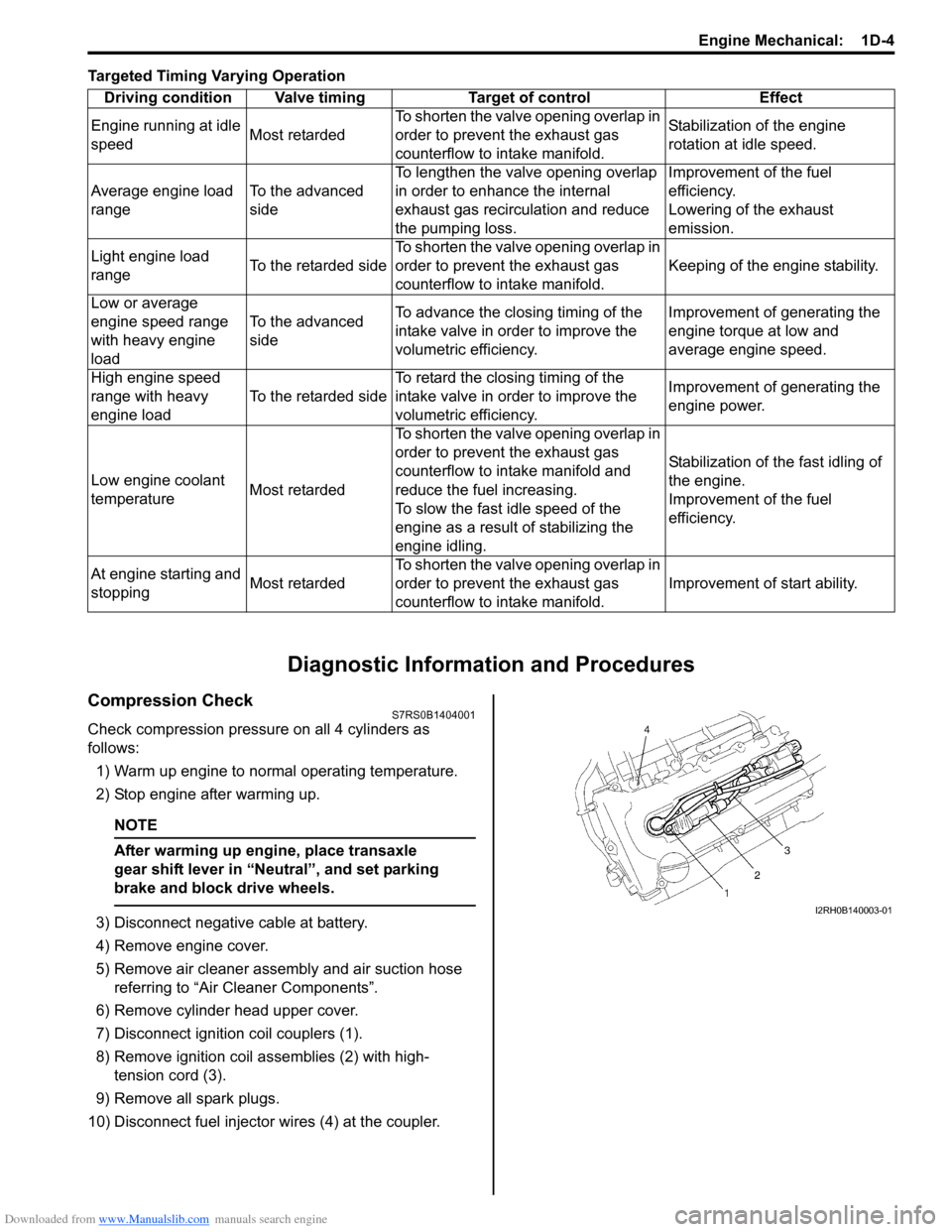
Targeted Timing Varying Operation
Diagnostic Information and Procedures
Compression CheckS7RS0B1404001
Check compression pressure on all 4 cylinders as
follows:
1) Warm up engine to normal operating temperature.
2) Stop engine after warming up.
NOTE
After warming up engine, place transaxle
gear shift lever in “Neutral”, and set parking
brake and block drive wheels.
3) Disconnect negative cable at battery.
4) Remove engine cover.
5) Remove air cleaner assembly and air suction hose referring to “Air Cleaner Components”.
6) Remove cylinder head upper cover.
7) Disconnect ignition coil couplers (1).
8) Remove ignition coil assemblies (2) with high- tension cord (3).
9) Remove all spark plugs.
10) Disconnect fuel injector wires (4) at the coupler. Driving condition Valve timing Target of control Effect
Engine running at idle
speed Most retardedTo shorten the valve opening overlap in
order to prevent the exhaust gas
counterflow to in
take manifold. Stabilization of the engine
rotation at idle speed.
Average engine load
range To the advanced
sideTo lengthen the valve opening overlap
in order to enhance the internal
exhaust gas recirculation and reduce
the pumping loss. Improvement of the fuel
efficiency.
Lowering of the exhaust
emission.
Light engine load
range To the retarded sideTo shorten the valve opening overlap in
order to prevent the exhaust gas
counterflow to in
take manifold. Keeping of the engine stability.
Low or average
engine speed range
with heavy engine
load To the advanced
side
To advance the closing timing of the
intake valve in order to improve the
volumetric efficiency. Improvement of generating the
engine torque at low and
average engine speed.
High engine speed
range with heavy
engine load To the retarded sideTo retard the closing timing of the
intake valve in order to improve the
volumetric efficiency. Improvement of generating the
engine power.
Low engine coolant
temperature Most retardedTo shorten the valve opening overlap in
order to prevent the exhaust gas
counterflow to intake manifold and
reduce the fuel increasing.
To slow the fast idle speed of the
engine as a result of stabilizing the
engine idling. Stabilization of the fast idling of
the engine.
Improvement of the fuel
efficiency.
At engine starting and
stopping Most retardedTo shorten the valve opening overlap in
order to prevent the exhaust gas
counterflow to in
take manifold. Improvement of start ability.I2RH0B140003-01
Page 290 of 1496
Downloaded from www.Manualslib.com manuals search engine 1D-5 Engine Mechanical:
11) Connect negative cable at battery.
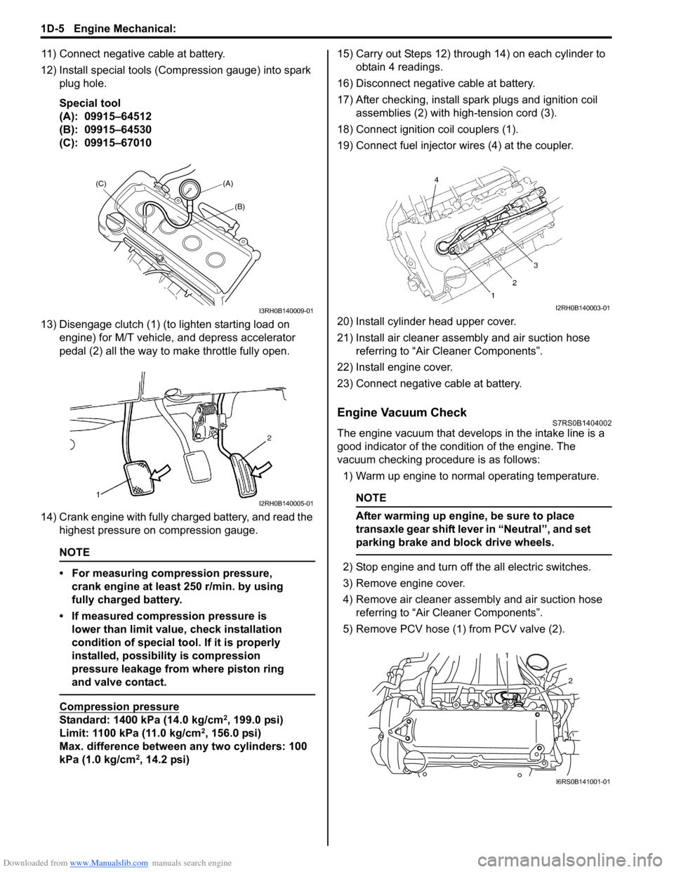
12) Install special tools (Compression gauge) into spark plug hole.
Special tool
(A): 09915–64512
(B): 09915–64530
(C): 09915–67010
13) Disengage clutch (1) (to lighten starting load on engine) for M/T vehicle, and depress accelerator
pedal (2) all the way to make throttle fully open.
14) Crank engine with fully charged battery, and read the highest pressure on compression gauge.
NOTE
• For measuring compression pressure, crank engine at least 250 r/min. by using
fully charged battery.
• If measured compression pressure is lower than limit value, check installation
condition of special tool. If it is properly
installed, possibility is compression
pressure leakage from where piston ring
and valve contact.
Compression pressure
Standard: 1400 kPa (14.0 kg/cm2, 199.0 psi)
Limit: 1100 kPa (11.0 kg/cm2, 156.0 psi)
Max. difference between any two cylinders: 100
kPa (1.0 kg/cm
2, 14.2 psi) 15) Carry out Steps 12) through 14) on each cylinder to
obtain 4 readings.
16) Disconnect negative cable at battery.
17) After checking, install spark plugs and ignition coil assemblies (2) with high-tension cord (3).
18) Connect ignition coil couplers (1).
19) Connect fuel injector wires (4) at the coupler.
20) Install cylinder head upper cover.
21) Install air cleaner assembly and air suction hose referring to “Air Cleaner Components”.
22) Install engine cover.
23) Connect negative cable at battery.
Engine Vacuum CheckS7RS0B1404002
The engine vacuum that develops in the intake line is a
good indicator of the condition of the engine. The
vacuum checking procedure is as follows:
1) Warm up engine to normal operating temperature.
NOTE
After warming up engine, be sure to place
transaxle gear shift lever in “Neutral”, and set
parking brake and block drive wheels.
2) Stop engine and turn off the all electric switches.
3) Remove engine cover.
4) Remove air cleaner assembly and air suction hose referring to “Air Cleaner Components”.
5) Remove PCV hose (1) from PCV valve (2).
(A)
(C)
(B)
I3RH0B140009-01
I2RH0B140005-01
I2RH0B140003-01
2
1
I6RS0B141001-01
Page 416 of 1496
Downloaded from www.Manualslib.com manuals search engine 1J-6 Charging System:
Generator Test (Overcharged Battery Check)S7RS0B1A04004
1) To determine battery condition, refer to “Battery Description”.
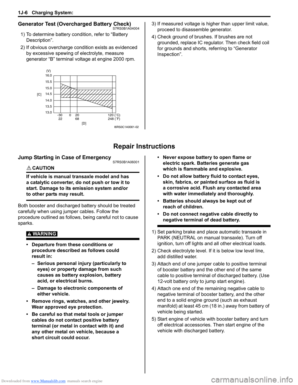
2) If obvious overcharge condition exists as evidenced by excessive spewing of electrolyte, measure
generator “B” terminal voltage at engine 2000 rpm. 3) If measured voltage is higher than upper limit value,
proceed to disassemble generator.
4) Check ground of brushes. If brushes are not grounded, replace IC regulator. Then check field coil
for grounds and shorts, referring to “Generator
Inspection”.
Repair Instructions
Jump Starting in Case of EmergencyS7RS0B1A06001
CAUTION!
If vehicle is manual transaxle model and has
a catalytic converter, do not push or tow it to
start. Damage to its emission system and/or
to other parts may result.
Both booster and discharged battery should be treated
carefully when using ju mper cables. Follow the
procedure outlined as follows, being careful not to cause
sparks.
WARNING!
• Departure from these conditions or procedure described as follows could
result in:
– Serious personal injury (particularly to eyes) or property damage from such
causes as battery explosion, battery
acid, or electrical burns.
– Damage to electronic components of either vehicle.
• Remove rings, watches, and other jewelry. Wear approved eye protection.
• Be careful so that metal tools or jumper cables do not contact positive battery
terminal (or metal in contact with it) and
any other metal on vehicle, because a
short circuit could occur. • Never expose battery to open flame or
electric spark. Batteries generate gas
which is flammable and explosive.
• Do not allow battery fluid to contact eyes, skin, fabrics, or painted surface as fluid is
a corrosive acid. Flush any contacted area
with water immediately and thoroughly.
• Batteries should always be kept out of reach of children.
• Do not connect negative cable directly to negative terminal of dead battery.
1) Set parking brake and place automatic transaxle in PARK (NEUTRAL on manual transaxle). Turn off
ignition, turn off lights and all other electrical loads.
2) Check electrolyte level. If it is below low level line, add distilled water.
3) Attach end of one jumper cable to positive terminal of booster battery and the other end of the same
cable to positive terminal of discharged battery. (Use
12-volt battery only to jump start engine).
4) Attach one end of the remaining negative cable to negative terminal of booster battery, and the other
end to a solid engine ground (such as exhaust
manifold) at least 45 cm (18 in.) away from battery of
vehicle being started.
5) Start engine of vehicle with booster battery and turn off electrical accessories. Then start engine of the
vehicle with discharged battery.
16.0
15.5
15.0
14.5
14.0
13.5
13.0 -30 0 20
[C]
[D]
68
22120 (˚C)
248 (˚F)
(V)
I6RS0C1A0001-02
Page 495 of 1496
Downloaded from www.Manualslib.com manuals search engine Table of Contents 4- i
4
Section 4
CONTENTS
Brakes
Precautions ................................................. 4-1
Precautions............................................................. 4-1
Precautions for Brakes .......................................... 4-1
Brake Control System and Diagnosis ... 4A-1
Precautions........................................................... 4A-1Precautions on Brake .......................................... 4A-1
General Description ............................................. 4A-1 Brakes Construction ............................................ 4A-1
Brake Pedal Foot Protection System Construction ...................................................... 4A-2
Front Brake Hose / Pipe Co nstruction................. 4A-3
Rear Brake Hose / Pipe Construction ................. 4A-4
Diagnostic Information and Procedures ............ 4A-4 Brakes Diagnosis Note ....................................... 4A-4
Brakes Symptom Diagnosis ................................ 4A-5
Repair Instructions .............................................. 4A-7 Brake Pedal Components ................................... 4A-7
Brake Pedal Free Height Inspection ................... 4A-7
Brake Pedal Play Inspection ............................... 4A-7
Excessive Pedal Travel Inspection ..................... 4A-8
Brake Fluid Level Inspection ............................... 4A-8
Stop Light Switch Adjustment ............................. 4A-8
Air Bleeding of Brake System ............................. 4A-9
Front Brake Hose / Pipe Removal and Installation ....................................................... 4A-10
Rear Brake Hose / Pipe Removal and Installation ....................................................... 4A-10
Brake Hose and Pipe Inspection ....................... 4A-11
Master Cylinder Components............................ 4A-11
Master Cylinder Assembly Removal and Installation ....................................................... 4A-12
Master Cylinder Rese rvoir Removal and
Installation ....................................................... 4A-13
Master Cylinder Assemb ly Disassembly and
Assembly ........................................................ 4A-14
Master Cylinder Assembly Inspection ............... 4A-15
Brake Booster Components .............................. 4A-15
Booster Operation Inspection ........................... 4A-16
Brake Booster Removal and Installation ........... 4A-17
Brake Booster Inspection and Adjustment ........ 4A-18
Specifications ..................................................... 4A-18
Tightening Torque Specifications ...................... 4A-18
Special Tools and Equipmen t ........................... 4A-18 Recommended Service Material ....................... 4A-18
Front Brakes .......
..................................... 4B-1
Repair Instructions ........... ...................................4B-1
Front Disc Brake Components ............................ 4B-1
Front Disc Brake Pad On-Vehicle Inspection ...... 4B-2
Front Disc Brake Pad Removal and Installation ......................................................... 4B-2
Front Disc Brake Pad Inspection......................... 4B-3
Front Disc Brake Ca liper Removal and
Installation ......................................................... 4B-3
Front Disc Brake Caliper Disassembly and Assembly........................................................... 4B-4
Front Disc Brake Caliper In spection.................... 4B-6
Front Brake Disc Removal and Installation ......... 4B-6
Front Brake Disc Inspection ................................ 4B-7
Specifications .................... ...................................4B-8
Tightening Torque Specifications ........................ 4B-8
Special Tools and Equipmen t .............................4B-8
Recommended Service Material ......................... 4B-8
Special Tool ........................................................ 4B-8
Rear Brakes................... ........................... 4C-1
Repair Instructions ........... ...................................4C-1
Rear Disc Brake Components.............................4C-1
Rear Disc Brake Pad Removal and Installation .........................................................4C-2
Rear Disc Brake Caliper Removal and Installation .........................................................4C-3
Rear Disc Brake Pad Inspection .........................4C-6
Rear Disc Brake Caliper Disassembly and Assembly...........................................................4C-6
Rear Disc Brake Caliper Inspection ....................4C-8
Rear Flexible Hose Remova l and Installation .....4C-8
Rear Brake Disc Removal and Installation..........4C-9
Rear Brake Disc Inspection.................................4C-9
Specifications .................... .................................4C-10
Tightening Torque Specifications ......................4C-10
Special Tools and Equipmen t ...........................4C-11
Recommended Service Material .......................4C-11
Special Tool ......................................................4C-11
Parking Brake ................. ......................... 4D-1
General Description .............................................4D-1
Parking Brake Cable Construction ......................4D-1
Page 496 of 1496

Downloaded from www.Manualslib.com manuals search engine 4-ii Table of Contents
Repair Instructions ..............................................4D-2Parking Brake Inspection and Adjustment ..........4D-2
Parking Brake Cable Removal and Installation ......................................................... 4D-3
Parking Brake Lever Removal and Installation ....4D-3
Specifications .... ...................................................4D-4
Tightening Torque Specifications ........................4D-4
ABS ........................................... .................4E-1
Precautions........................................................... 4E-1
Precautions in Diagnosing Troubles ................... 4E-1
Precautions in On-Vehicle Service...................... 4E-1
Precautions in Hydraulic Unit Operation Check ................................................................ 4E-1
General Description ............................................. 4E-2 ABS Description .................................................. 4E-2
ABS Hydraulic Unit / Control Module Assembly Description ....................................... 4E-2
CAN Communication System Description........... 4E-3
Schematic and Routing Diagram ........................ 4E-4 ABS Schematic ................................................... 4E-4
ABS Wiring Circuit Diagram ................................ 4E-5
Component Location ........... ................................ 4E-7
ABS Components Location ................................. 4E-7
Front Wheel Speed Sensor Components Location ............................................................ 4E-7
Rear Wheel Speed Sensor Components Location ............................................................ 4E-8
Diagnostic Information and Procedures ............ 4E-8 ABS Check .......................................................... 4E-8
ABS Warning Light Check................................. 4E-10
EBD Warning Light (Brake Warning Light) Check .............................................................. 4E-10
DTC Check........................................................ 4E-11
DTC Table ......................................................... 4E-11
DTC Clearance ................................................. 4E-12
Scan Tool Data ................................................. 4E-12
ABS Warning Light Does Not Come ON at Ignition Switch ON .......................................... 4E-13
ABS Warning Light Comes ON Steady ............. 4E-14
EBD Warning Light (Brake Warning Light) Comes ON Steady .......................................... 4E-15
Serial Data Link Circuit Check .......................... 4E-16
DTC C1021, C1022 / C1025, C1026 / C1031, C1032 / C1035, C1036: Right-Front / Left-
Front / Right-Rear / Left-Rear Wheel Speed
Sensor Circuit or Sensor Ring ........................ 4E-18
DTC C1041 / C1045 / C1051 / C1055, DTC C1042 / C1046 / C1052 / C1056: Right-Front
/ Left-Front / Right-Rear / Left-Rear Inlet
Solenoid Circuit, Right-Front / Left-Front /
Right-Rear / Left-Rear Outlet Solenoid
Circuit .............................................................. 4E-20
DTC C1057: Power Source Circuit ................... 4E-21
DTC C1061: ABS Pump Motor and/or Motor Driver Circuit ................................................... 4E-22
DTC C1063: Solenoid Valve Power Supply Driver Circuit ................................................... 4E-23
DTC C1071: ABS Control Module..................... 4E-24 DTC U1073: Control Module Communication
Bus Off ............................................................ 4E-25
DTC U1100: Lost Communication with ECM (Reception Error)............................................. 4E-27
Repair Instructions ............ ................................ 4E-28
ABS Hydraulic Unit Operati on Check................ 4E-28
ABS Hydraulic Unit / Control Module
Assembly Components ...... ............................. 4E-29
ABS Hydraulic Unit / Control Module
Assembly On-Vehicle Inspection .................... 4E-29
ABS Hydraulic Unit / Control Module
Assembly Removal and Inst allation ................ 4E-29
Front / Rear Wheel Speed Sensor On-Vehicle Inspection ........................................................ 4E-31
Front Wheel Speed Sensor Removal and Installation ....................................................... 4E-32
Front Wheel Speed Sensor Inspection ............. 4E-32
Rear Wheel Speed Sensor Removal and Installation ....................................................... 4E-33
Rear Wheel Speed Sensor Inspection .............. 4E-34
Front Wheel Encoder On-Veh icle Inspection .... 4E-34
Front wheel Enco der Removal and
Installation ....................................................... 4E-34
Rear Wheel Encoder On-Veh icle Inspection..... 4E-34
Rear Wheel Encoder Removal and Installation ....................................................... 4E-34
Specifications ..................... ................................ 4E-35
Tightening Torque Specifications ...................... 4E-35
Special Tools and Equipmen t ........................... 4E-35
Special Tool ...................................................... 4E-35
Electronic Stability Prog ram ...................4F-1
Precautions ........................................................... 4F-1
Precautions in Diagnosing Troubles ................... 4F-1
Precautions in On-Vehicle Service...................... 4F-1
Precautions in Hydraulic Unit Operation Check ................................................................ 4F-1
Precautions in Sensor Calibration ....................... 4F-1
Precautions in Speedometer Test or Other Tests ................................................................. 4F-2
General Description ............................................. 4F-2 Electronic Stability Program Description ............. 4F-2
Electronic Stability Program Construction ........... 4F-3
ESP® Hydraulic Unit / Control Module
Assembly Description........................................ 4F-5
Warning Lamp, Indicator Lamp Description ........ 4F-6
CAN Communication System Description........... 4F-6
CAN Communication System For Electronic Stability Program Description ............................ 4F-7
Schematic and Routing Diagram ........................ 4F-8 Electronic Stability Program Schematic .............. 4F-8
Electronic Stability Program Wiring Circuit Diagram............................................................. 4F-9
Component Location ............ ............................. 4F-11
Electronic Stability Program Component
Location........................................................... 4F-11
Diagnostic Information and Procedures .......... 4F-12 Electronic Stability Program System Check ...... 4F-12
ESP® Warning lamp Check .............................. 4F-14
Page 503 of 1496
Downloaded from www.Manualslib.com manuals search engine Brake Control System and Diagnosis: 4A-5
If deterioration of rubber is evident, disassemble all
hydraulic parts and wash with alcohol. Dry these parts
with compressed air before assembly to keep alcohol out
of the system. Replace all rubber parts in the system,
including hoses. Also, when working on the brake
mechanisms, check for fluid on the linings.
If excessive fluid is found, replace the pads. If master cylinder piston seals
are satisfactory, check for
leakage or excessive heat co nditions. If leakage is not
found, drain fluid, flush with brake fluid, refill and bleed
system.
The system must be flushed if there is any doubt as to
the grade of fluid in the system or if fluid has been used
which contained parts that have been subjected to
contaminated fluid.
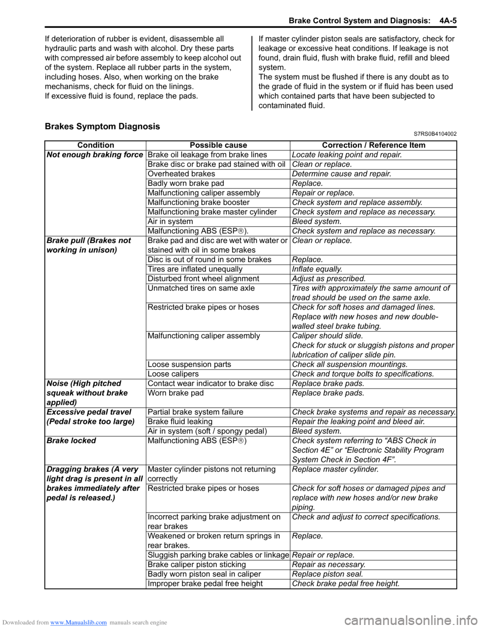
Brakes Symptom DiagnosisS7RS0B4104002
Condition Possible cause Correction / Reference Item
Not enough braking force Brake oil leakage from brake lines Locate leaking point and repair.
Brake disc or brake pad stained with oil Clean or replace.
Overheated brakes Determine cause and repair.
Badly worn brake pad Replace.
Malfunctioning caliper assembly Repair or replace.
Malfunctioning brake booster Check system and replace assembly.
Malfunctioning brake master cylinder Check system and replace as necessary.
Air in system Bleed system.
Malfunctioning ABS (ESP ®). Check system and replace as necessary.
Brake pull (Brakes not
working in unison) Brake pad and disc are wet with water or
stained with oil in some brakes Clean or replace.
Disc is out of round in some brakes Replace.
Tires are inflated unequally Inflate equally.
Disturbed front wheel alignment Adjust as prescribed.
Unmatched tires on same axle Tires with approximately the same amount of
tread should be used on the same axle.
Restricted brake pipes or hoses Check for soft hoses and damaged lines.
Replace with new hoses and new double-
walled steel brake tubing.
Malfunctioning caliper assembly Caliper should slide.
Check for stuck or sluggish pistons and proper
lubrication of caliper slide pin.
Loose suspension parts Check all suspension mountings.
Loose calipers Check and torque bolts to specifications.
Noise (High pitched
squeak without brake
applied) Contact wear indicator to brake disc
Replace brake pads.
Worn brake pad Replace brake pads.
Excessive pedal travel
(Pedal stroke too large) Partial brake system failure
Check brake systems and repair as necessary.
Brake fluid leaking Repair the leaking point and bleed air.
Air in system (soft / spongy pedal) Bleed system.
Brake locked Malfunctioning ABS (ESP®) Check system referri ng to “ABS Check in
Section 4E” or “Electronic Stability Program
System Check in Section 4F”.
Dragging brakes (A very
light drag is present in all
brakes immediately after
pedal is released.) Master cylinder pistons not returning
correctly
Replace master cylinder.
Restricted brake pipes or hoses Check for soft hoses or damaged pipes and
replace with new hoses and/or new brake
piping.
Incorrect parking brake adjustment on
rear brakes Check and adjust to correct specifications.
Weakened or broken return springs in
rear brakes. Replace.
Sluggish parking brake cables or linkage Repair or replace.
Brake caliper piston sticking Repair as necessary.
Badly worn piston seal in caliper Replace piston seal.
Improper brake pedal free height Check brake pedal free height.