tape SUZUKI SWIFT 2008 2.G Service Workshop Manual
[x] Cancel search | Manufacturer: SUZUKI, Model Year: 2008, Model line: SWIFT, Model: SUZUKI SWIFT 2008 2.GPages: 1496, PDF Size: 34.44 MB
Page 13 of 1496
Downloaded from www.Manualslib.com manuals search engine Precautions: 00-8
Precautions for Electrical Circuit ServiceS7RS0B0000008
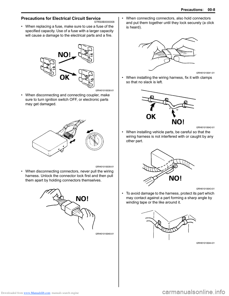
• When replacing a fuse, make sure to use a fuse of the specified capacity. Use of a fuse with a larger capacity
will cause a damage to the electrical parts and a fire.
• When disconnecting and connecting coupler, make sure to turn ignition switch OFF, or electronic parts
may get damaged.
• When disconnecting connectors, never pull the wiring harness. Unlock the connecto r lock first and then pull
them apart by holding connectors themselves. • When connecting connectors, also hold connectors
and put them together until th ey lock securely (a click
is heard).
• When installing the wiring harness, fix it with clamps so that no slack is left.
• When installing vehicle parts, be careful so that the wiring harness is not interfered with or caught by any
other part.
• To avoid damage to the harnes s, protect its part which
may contact against a part forming a sharp angle by
winding tape or the like around it.
I2RH01010038-01
I2RH01010039-01
I2RH01010040-01
I2RH01010041-01
I2RH01010042-01
I2RH01010043-01
I2RH01010044-01
Page 291 of 1496
Downloaded from www.Manualslib.com manuals search engine Engine Mechanical: 1D-6
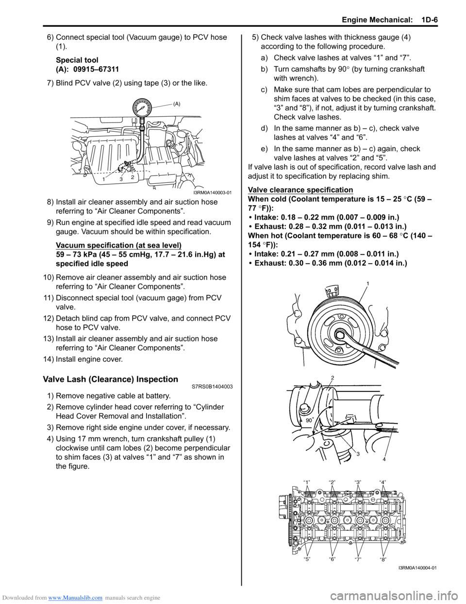
6) Connect special tool (Vacuum gauge) to PCV hose (1).
Special tool
(A): 09915–67311
7) Blind PCV valve (2) using tape (3) or the like.
8) Install air cleaner assembly and air suction hose referring to “Air Cleaner Components”.
9) Run engine at specified idle speed and read vacuum gauge. Vacuum should be within specification.
Vacuum specification (at sea level)
59 – 73 kPa (45 – 55 cmHg, 17.7 – 21.6 in.Hg) at
specified idle speed
10) Remove air cleaner assembly and air suction hose referring to “Air Cleaner Components”.
11) Disconnect special tool (vacuum gage) from PCV valve.
12) Detach blind cap from PCV valve, and connect PCV hose to PCV valve.
13) Install air cleaner assembly and air suction hose referring to “Air Cleaner Components”.
14) Install engine cover.
Valve Lash (Clearance) InspectionS7RS0B1404003
1) Remove negative cable at battery.
2) Remove cylinder head cover referring to “Cylinder Head Cover Removal and Installation”.
3) Remove right side engine under cover, if necessary.
4) Using 17 mm wrench, turn crankshaft pulley (1) clockwise until cam lobes (2) become perpendicular
to shim faces (3) at valves “1” and “7” as shown in
the figure. 5) Check valve lashes with thickness gauge (4)
according to the following procedure.
a) Check valve lashes at valves “1” and “7”.
b) Turn camshafts by 90 ° (by turning crankshaft
with wrench).
c) Make sure that cam lobes are perpendicular to shim faces at valves to be checked (in this case,
“3” and “8”), if not, adjust it by turning crankshaft.
Check valve lashes.
d) In the same manner as b) – c), check valve
lashes at valves “4” and “6”.
e) In the same manner as b) – c) again, check valve lashes at valves “2” and “5”.
If valve lash is out of specification, record valve lash and
adjust it to specification by replacing shim.
Valve clearance specification
When cold (Coolant te mperature is 15 – 25 °C (59 –
77 °F)):
• Intake: 0.18 – 0.22 mm (0.007 – 0.009 in.)
• Exhaust: 0.28 – 0.32 mm (0.011 – 0.013 in.)
When hot (Coolant temperature is 60 – 68 °C (140 –
154 °F)):
• Intake: 0.21 – 0.27 mm (0.008 – 0.011 in.)
• Exhaust: 0.30 – 0.36 mm (0.012 – 0.014 in.)
(A)
13 2
I3RM0A140003-01
I3RM0A140004-01
Page 332 of 1496
Downloaded from www.Manualslib.com manuals search engine 1D-47 Engine Mechanical:
Cylinders, Pistons and Piston Rings InspectionS7RS0B1406032
Cylinder
Visual inspection
Inspect cylinder walls for scratches, roughness or ridges
which indicate excessive wear. If cylinder bore is very
rough or deeply scratched, or ridged, rebore cylinder and
use over size piston.
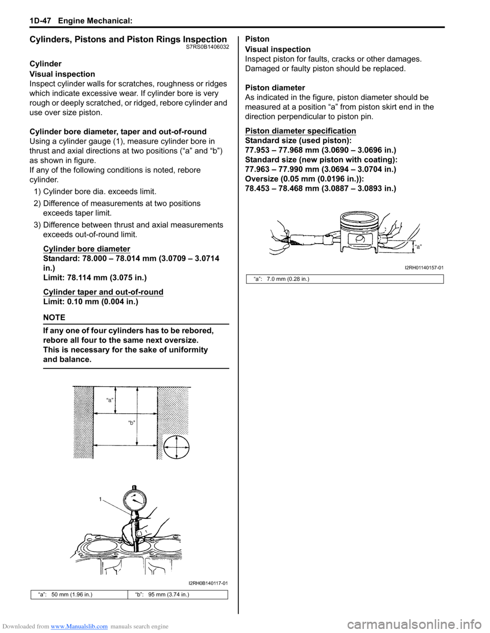
Cylinder bore diameter, taper and out-of-round
Using a cylinder gauge (1), measure cylinder bore in
thrust and axial directions at two positions (“a” and “b”)
as shown in figure.
If any of the following conditions is noted, rebore
cylinder.1) Cylinder bore dia. exceeds limit.
2) Difference of measurements at two positions exceeds taper limit.
3) Difference between thrust and axial measurements exceeds out-of-round limit.
Cylinder bore diameter
Standard: 78.000 – 78.014 mm (3.0709 – 3.0714
in.)
Limit: 78.114 mm (3.075 in.)
Cylinder taper and out-of-round
Limit: 0.10 mm (0.004 in.)
NOTE
If any one of four cylinders has to be rebored,
rebore all four to the same next oversize.
This is necessary for the sake of uniformity
and balance.
Piston
Visual inspection
Inspect piston for faults, cracks or other damages.
Damaged or faulty piston should be replaced.
Piston diameter
As indicated in the figure, piston diameter should be
measured at a position “a” from piston skirt end in the
direction perpendicular to piston pin.
Piston diameter specification
Standard size (used piston):
77.953 – 77.968 mm (3.0690 – 3.0696 in.)
Standard size (new piston with coating):
77.963 – 77.990 mm (3.0694 – 3.0704 in.)
Oversize (0.05 mm (0.0196 in.)):
78.453 – 78.468 mm (3.0887 – 3.0893 in.)
“a”: 50 mm (1.96 in.) “b”: 95 mm (3.74 in.)
I2RH0B140117-01
“a”: 7.0 mm (0.28 in.)
I2RH01140157-01
Page 335 of 1496
Downloaded from www.Manualslib.com manuals search engine Engine Mechanical: 1D-50
Connecting rod bearing cap bolt deformation
(Plastic deformation tightening bolt)
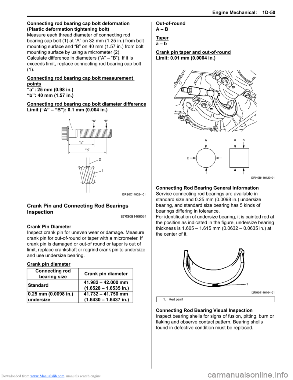
Measure each thread diameter of connecting rod
bearing cap bolt (1) at “A” on 32 mm (1.25 in.) from bolt
mounting surface and “B” on 40 mm (1.57 in.) from bolt
mounting surface by using a micrometer (2).
Calculate difference in diameters (“A” – “B”). If it is
exceeds limit, replace connecting rod bearing cap bolt
(1).
Connecting rod bearing cap bolt measurement
points
“a”: 25 mm (0.98 in.)
“b”: 40 mm (1.57 in.)
Connecting rod bearing cap bolt diameter difference
Limit (“A” – “B”): 0.1 mm (0.004 in.)
Crank Pin and Connecting Rod Bearings
Inspection
S7RS0B1406034
Crank Pin Diameter
Inspect crank pin for uneven wear or damage. Measure
crank pin for out-of-round or taper with a micrometer. If
crank pin is damaged or out-of round or taper is out of
limit, replace crankshaft or regrind crank pin to undersize
and use undersize bearing.
Crank pin diameter
Out-of-round
A – B
Ta p e r
a – b
Crank pin taper and out-of-round
Limit: 0.01 mm (0.0004 in.)
Connecting Rod Bearing General Information
Service connecting rod be arings are available in
standard size and 0.25 mm (0.0098 in.) undersize
bearing, and standard size bearing has 5 kinds of
bearings differing in tolerance.
For identification of undersize bearing, it is painted red at
the position as indicated in the figure, undersize bearing
thickness is 1.605 – 1.615 mm (0.0632 – 0.0635 in.) at
the center of it.
Connecting Rod Bearing Visual Inspection
Inspect bearing shells for signs of fusion, pitting, burn or
flaking and observe contact pattern. Bearing shells
found in defective condition must be replaced.
Connecting rod
bearing size Crank pin diameter
Standard 41.982 – 42.000 mm
(1.6528 – 1.6535 in.)
0.25 mm (0.0098 in.)
undersize 41.732 – 41.750 mm
(1.6430 – 1.6437 in.)
I6RS0C140024-01
1. Red paint
I2RH0B140120-01
I2RH01140164-01
Page 343 of 1496
Downloaded from www.Manualslib.com manuals search engine Engine Mechanical: 1D-58
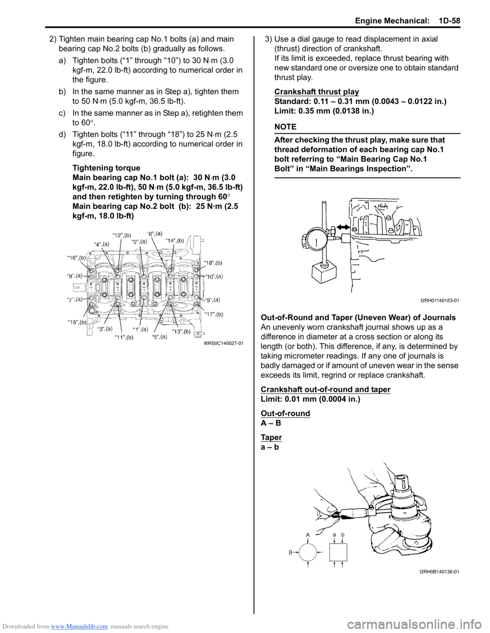
2) Tighten main bearing cap No.1 bolts (a) and main bearing cap No.2 bolts (b ) gradually as follows.
a) Tighten bolts (“1” through “10”) to 30 N ⋅m (3.0
kgf-m, 22.0 lb-ft) according to numerical order in
the figure.
b) In the same manner as in Step a), tighten them to 50 N ⋅m (5.0 kgf-m, 36.5 lb-ft).
c) In the same manner as in Step a), retighten them to 60 °.
d) Tighten bolts (“11” through “18”) to 25 N ⋅m (2.5
kgf-m, 18.0 lb-ft) according to numerical order in
figure.
Tightening torque
Main bearing cap No.1 bolt (a): 30 N ⋅m (3.0
kgf-m, 22.0 lb-ft), 50 N ⋅m (5.0 kgf-m, 36.5 lb-ft)
and then retighten by turning through 60 °
Main bearing cap No.2 bolt (b): 25 N·m (2.5
kgf-m, 18.0 lb-ft) 3) Use a dial gauge to read displacement in axial
(thrust) direction of crankshaft.
If its limit is exceeded, replace thrust bearing with
new standard one or oversize one to obtain standard
thrust play.
Crankshaft thrust play
Standard: 0.11 – 0.31 mm (0.0043 – 0.0122 in.)
Limit: 0.35 mm (0.0138 in.)
NOTE
After checking the thrust play, make sure that
thread deformation of each bearing cap No.1
bolt referring to “Main Bearing Cap No.1
Bolt” in “Main Bear ings Inspection”.
Out-of-Round and Taper (Uneven Wear) of Journals
An unevenly worn crankshaft journal shows up as a
difference in diameter at a cross section or along its
length (or both). This difference, if any, is determined by
taking micrometer readings. If any one of journals is
badly damaged or if amount of uneven wear in the sense
exceeds its limit, regrind or replace crankshaft.
Crankshaft out-of-round and taper
Limit: 0.01 mm (0.0004 in.)
Out-of-round
A – B
Ta p e r
a – b
I6RS0C140027-01
I2RH01140183-01
I2RH0B140138-01
Page 355 of 1496
Downloaded from www.Manualslib.com manuals search engine Engine Lubrication System: 1E-3
6) Start engine and warm engine up to normal operating temperature.
NOTE
Be sure to shift transaxle gear shift lever in
“Neutral” (shift select lever in “P” range for
A/T vehicle), set parking brake and block
drive wheels.
7) After warming up, raise engine speed to 4,000 r/min. and measure oil pressure.
Oil pressure specification
More than 270 kPa (2.7 kg/cm2, 39.8 psi) at 4,000
r/min. (rpm)
8) After checking oil pressure, stop engine and remove oil pressure gauge and attachment.
9) Before reinstalling oil pressure switch (2), be sure to
wrap its screw threads with sealing tape (1) and
tighten switch to specified torque.
NOTE
If sealing tape edge is bulged out from screw
threads of switch, cut it off.
Tightening torque
Oil pressure switch (a): 13 N·m (1.3 kgf-m, 9.5
lb-ft) 10) Start engine and check oil pressure switch for oil
leakage. If oil leakage is found, repair it.
11) Connect oil pressure switch coupler (1).
Repair Instructions
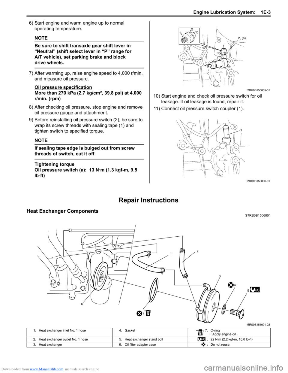
Heat Exchanger ComponentsS7RS0B1506001
I2RH0B150005-01
I2RH0B150006-01
3
4
5
7
6
(a)
2
1
I6RS0B151001-02
1. Heat exchanger inlet No. 1 hose 4. Gasket7. O-ring
: Apply engine oil.
2. Heat exchanger outlet No. 1 hose 5. Heat exchanger stand bolt : 22 N⋅m (2.2 kgf-m, 16.0 lb-ft)
3. Heat exchanger 6. Oil filter adapter case : Do not reuse.
Page 815 of 1496
Downloaded from www.Manualslib.com manuals search engine Manual Transmission/Transaxle: 5B-1
Transmission / Transaxle
Manual Transmission/Transaxle
General Description
Manual Transaxle Construction and ServicingS7RS0B5201001
The transaxle provides five forward speeds and one reverse speed by means of three synchromeshs and three shafts
(input shaft, countershaft and reverse gear shaft). All forward gears are in constant mesh, and reverse uses a sliding
idler gear arrangement.
The low speed synchronizer sleeve & hub is mounted on countershaft and engaged with countershaft 1st gear or 2nd
gear, while the high speed synchronizer sleeve & hub is don e on input shaft and engaged with input shaft 3rd gear or
4th gear. The 5th speed synchronizer sleev e & hub on input shaft is engaged with input shaft fifth gear mounted on the
input shaft.
To prevent the cracking noise from the reverse gear when shifting transaxle gear into the reverse gear, the reverse
shift braking device is used.
The device utilizes the 5th synchromesh, which is the lever synchro type, to appl y the brake on the input shaft rotation.
The double cone synchronizing mechanism is provided to 2nd gear synchromesh device for high performance of
shifting to 2nd gear.
The countershaft turns the final gear and differential assembly, thereby turning the front drive shafts which are
attached to the front wheels.
For servicing, it is ne cessary to use genuine sealant or its equivalent on mating surfaces of transaxle case which is
made of aluminum. The case fastening bolts must be tight ened to specified torque by means of torque wrench. It is
also important that all parts are thoroughly cleaned with cleaning fluid and air dried before reassembling.
Further, care must be taken to adjust preload of count ershaft taper roller bearings. New synchronizer rings are
prohibited from being lapped with respective gear cones by using lapping compound before they are assembled.
Page 853 of 1496
Downloaded from www.Manualslib.com manuals search engine Clutch: 5C-1
Transmission / Transaxle
Clutch
General Description
Clutch ConstructionS7RS0B5301001
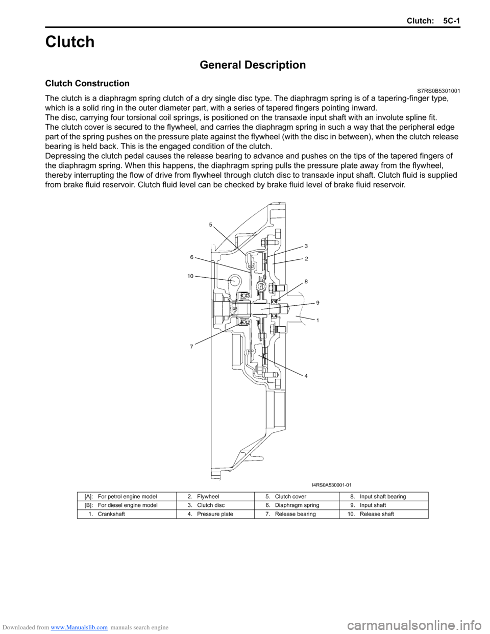
The clutch is a diaphragm spring clutch of a dry single disc type. The diaphragm spring is of a tapering-finger type,
which is a solid ring in the outer diameter part, with a series of tapered fingers pointing inward.
The disc, carrying four torsional coil springs, is positione d on the transaxle input shaft with an involute spline fit.
The clutch cover is secured to the flywheel, and carries the diaphragm spring in such a way that the peripheral edge
part of the spring pushes on the pressure plate against the flywheel (with the disc in between), when the clutch release
bearing is held back. This is the engaged condition of the clutch.
Depressing the clutch pedal c auses the release bearing to advance and pushes on the tips of the tapered fingers of
the diaphragm spring. When this happens, the diaphragm sp ring pulls the pressure plate away from the flywheel,
thereby interrupting the flow of drive from flywheel through clutch disc to transaxle input shaft. Clutch fluid is supplied
from brake fluid reservoir. Clutch fluid level can be checked by brake fluid level of brake fluid reservoir.
[A]: For petrol engine model2. Flywheel5. Clutch cover 8. Input shaft bearing
[B]: For diesel engine model 3. Clutch disc6. Diaphragm spring 9. Input shaft
1. Crankshaft 4. Pressure plate7. Release bearing 10. Release shaft
I4RS0A530001-01
Page 1150 of 1496

Downloaded from www.Manualslib.com manuals search engine 8B-112 Air Bag System:
• Check sensor (1) for dents, crack, deformation.
• Check sensor connector (sensor side and harness side), lock mechanism or sensor lead wire for
damage, crack, scorching or melting.
• Check connector terminals for bent, corrosion or rust. If any faulty condition is found in above checks,
replace.
Passenger Air Bag (Inflator) Module Repair
Harness Installation
S7RS0B8206017
Replace passenger air bag (inflator) module repair
harness (4) according to the following procedure when
the harness (1) connect ed with passenger air bag
(inflator) module of the air bag harness included in
instrument panel harness (2) and passenger air bag
(inflator) module connector (3) is damaged. 1) Disable air bag system. Re
fer to “Disabling Air Bag
System”.
2) Disconnect “L32” connector from floor harness located near the glove box.
3) Cut off passenger air bag (inflator) module harness (1) included in instrument panel harness (2) as
shown, and then fasten it to instrument panel
harness with vinyl tape for avoiding interference with
other parts.
4) Install passenger air bag (inflator) module repair harness (1) to floor harness (2), instrument panel
harness (3) and passenger air bag (inflator) module.CAUTION!
To avoid interference with other parts, fasten
the repair harness to in strument wire harness
with a clamp or vinyl tape as shown in figure.
5) Connect each connector securely till click is heard.
5. Driver air bag (inflator) module 7. Floor harness
6. Passenger air bag (inflator) module 8. Vinyl tape
1I4RS0A820082-01
7
4
6
6
2
28
1
3
5
5
7I4RS0A820103-01
1
I4RS0A820083-01
1
2
3
I4RS0A820085-01
Page 1331 of 1496
Downloaded from www.Manualslib.com manuals search engine Glass / Windows / Mirrors: 9E-4
Repair Instructions
Windshield Removal and InstallationS7RS0B9506001
Removal1) Clean both inside and outside of glass and around it.
2) Remove wiper arms and cowl top garnish.
3) Remove windshield side garnish.
4) Using tape, cover body surface around glass to prevent any damage.
5) Remove rear view mirror , sun visor and front pillar
trims (right & left).
6) If necessary, remove instrument panel. Refer to “Instrument Panel Removal and Installation in
Section 9C”.
7) If necessary, remove he ad lining. Refer to “Head
Lining Removal and Installation in Section 9H”.
8) Remove (or cut) windshield molding.
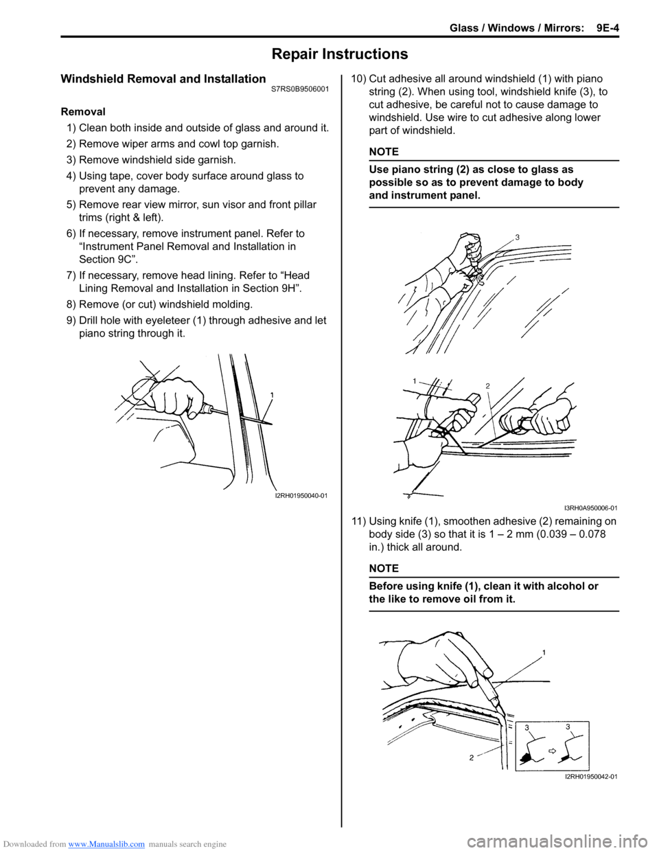
9) Drill hole with eyeleteer (1 ) through adhesive and let
piano string through it. 10) Cut adhesive all around windshield (1) with piano
string (2). When using tool, windshield knife (3), to
cut adhesive, be careful not to cause damage to
windshield. Use wire to cut adhesive along lower
part of windshield.
NOTE
Use piano string (2) as close to glass as
possible so as to prevent damage to body
and instrument panel.
11) Using knife (1), smoothen adhesive (2) remaining on body side (3) so that it is 1 – 2 mm (0.039 – 0.078
in.) thick all around.
NOTE
Before using knife (1), clean it with alcohol or
the like to remove oil from it.
I2RH01950040-01
I3RH0A950006-01
I2RH01950042-01