sensor SUZUKI SWIFT 2017 5.G User Guide
[x] Cancel search | Manufacturer: SUZUKI, Model Year: 2017, Model line: SWIFT, Model: SUZUKI SWIFT 2017 5.GPages: 336, PDF Size: 6.24 MB
Page 61 of 336
2-42
BEFORE DRIVING
74LH0-74E
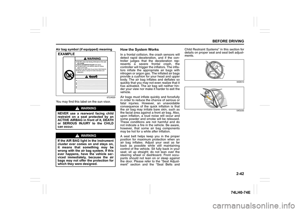
Air bag symbol (if equipped) meaning
67LH029
You may find this label on the sun visor.
How the System Works
In a frontal collision, the crash sensors will
detect rapid deceleration, and if the con-
troller judges that the deceleration rep-
resents a severe frontal crash, the
controller will trigger the inflators. The infla-
tors inflate the appropriate air bags with
nitrogen or argon gas. The inflated air bags
provide a cushion for your head and upper
body. The air bag inflates and deflates so
quickly that you may not even realize that it
has activated. The air bag will neither hin-
der your view nor make it harder to exit the
vehicle.
Air bags must inflate quickly and forcefully
in order to reduce the chance of serious or
fatal injuries. However, an unavoidable
consequence of the quick inflation is that
the air bag may irritate bare skin, such as
the facial area against a front air bag. Also,
upon inflation, a loud noise will occur and
some powder and smoke will be released.
These conditions are not harmful and do
not indicate a fire in the vehicle. Be aware,
however, that some air bag components
may be hot for a while after inflation.
A seat belt helps keep you in the proper
position for maximum protection when an
air bag inflates. Adjust your seat as far
back as possible while still maintaining
control of the vehicle. Sit fully back in your
seat; sit up straight; do not lean over the
steering wheel or dashboard. Front occu-
pants should not lean on or sleep against
the door. Please refer to the “Seat Adjust-
ment” section and the “Seat Belts andChild Restraint Systems” in this section for
details on proper seat and seat belt adjust-
ments.
65D610
54G535
WARNING
NEVER use a rearward facing child
restraint on a seat protected by an
ACTIVE AIRBAG in front of it, DEATH
or SERIOUS INJURY to the CHILD
can occur.
WARNING
If the AIR BAG light in the instrument
cluster ever comes on and stays on,
it means that something may be
wrong with the air bag system. If this
ever happens, have the vehicle ser-
viced immediately, because the air
bags may not offer the protection for
which they were designed.
EXAMPLE
Page 62 of 336
2-43
BEFORE DRIVING
74LH0-74E
Note that even though your vehicle may be
moderately damaged in a collision, the col-
lision may not have been severe enough to
trigger the air bags to inflate. If your vehicle
sustains ANY front-end or side damage,
have the air bag system inspected by an
authorized MARUTI SUZUKI dealer to
ensure it is in proper working order.
Your vehicle is equipped with a diagnostic
module which records information about
the air bag system if the air bags deploy in
a crash. The module records information
about overall system status, which sensors
activated the deployment.
Servicing the air bag systemIf the air bags inflate, have the air bags and
related components replaced by an autho-
rized MARUTI SUZUKI dealer as soon as
possible.
If your vehicle ever gets in deep water and
the driver’s floor is submerged, the air bag
controller could be damaged. If it does,
have the air bag system inspected by the
MARUTI SUZUKI dealer as soon as possi-
ble.
Special procedures are required for servic-
ing or replacing an air bag. For that reason,
only an authorized MARUTI SUZUKI
dealer should be allowed to service or
replace your air bags. Please remind any-
one who services your MARUTI SUZUKI
that it has air bags.Service on or around air bag components
or wiring must be performed only by an
authorized MARUTI SUZUKI dealer.
Improper service could result in unin-
tended air bag deployment or could render
the air bag inoperative. Either of these two
conditions may result in severe injury.
To prevent damage or unintended inflation
of the air bag system, be sure the battery
is disconnected and the ignition switch has
been in the “LOCK” position or the ignition
mode has been “LOCK” (OFF) for at least
90 seconds before performing any electri-
cal service work on your MARUTI SUZUKI.
Do not touch air bag system components
or wires. The wires are wrapped with yel-
low tape or yellow tubing, and the couplers
are yellow for easy identification.
Scrapping a vehicle that has an uninflated
air bag can be hazardous. Ask your dealer,
body repair shop or scrap yard for help
with disposal.
According to accident statistics, children
are safer when properly restrained on rear
seats than front passenger’s seat when-
ever possible, MARUTI SUZUKI recom-
mends that child restraint systems be
installed the rear seat.
WA R N I N G
• The driver should not lean over the
steering wheel. The front passenger
should not rest his or her body against
the dashboard, or otherwise get too
close to the dashboard. In these situa-
tions, the out-of-position occupant
would be too close to an inflating air
bag, and may suffer severe injury.
• Do not attach any objects to, or place
any objects over, the steering wheel or
dashboard. Do not place any objects
between the air bag and the driver or
front passenger. These objects may
interfere with air bag operation or may
be propelled by the air bag in the event
of a crash. Either of these conditions
may cause severe injury.
Page 77 of 336
2-58
BEFORE DRIVING
74LH0-74E
NOTE:
Depending on vehicle’s specifications,
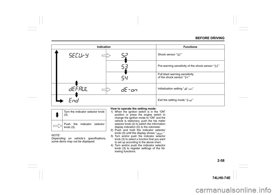
some items may not be displayed.How to operate the setting mode:
1) When the ignition switch is in the “ON”
position or press the engine switch to
change the ignition mode to “ON” and the
vehicle is stationary, push the trip meter
selector knob (2) to switch the information
display indication (D) to the odometer.
2) Push and hold the indicator selector
knob (3) until the display shows “ ”.
3) Turn and/or push the indicator selector
knob (3) to select a function that you want
to set up according to the above chart.
4) Turn and/or push the indicator selector
knob (3) to register settings of the fol-
lowing functions.Shock sensor “ ”
Pre-warning sensitivity of the shock sensor “ ”
Full blast warning sensitivity
of the shock sensor “ ”
Initialization setting “ ”
Exit the setting mode “ ” Indication Functions
Turn the indicator selector knob
(3).
Push the indicator selector
knob (3).
Page 78 of 336
2-59
BEFORE DRIVING
74LH0-74E
Automatic door locking function “ ”
• : Disable the automatic door
locking function
• : Lock all doors when the vehi-
cle speed reaches 15 km/h
(default setting)
•:
(For automatic transaxle vehi-
cle)
Lock all door when the gear-
shift lever is in other than “P”
Shock sensor “ ”
• : Enable the shock sensor
• : Disable the shock sensor
(default setting)
Pre-warning sensitivity of
the shock sensor “ ”
• : Disable the pre-warning
• to :
Adjust the pre-warning sensi-
tivity of shock sensor (Lowest
sensitivity level is L01 and
highest is L15, and default
setting is L14)Automatic door unlocking
function “ ”
• : Disable the automatic door
unlocking function
(default setting of vehicle with
keyless push start system)
• : (For automatic transaxle vehi-
cle)
Unlock all doors when the
gearshift lever is moved to the
“P” from other position
• : (Vehicle with keyless entry
system)
Unlock all doors when the key
is pulled out from the ignition
switch (default setting of vehi-
cle with keyless entry)
(Vehicle with keyless push
start system)
Unlock all doors when the
ignition mode is “LOCK”
(OFF)
Full blast warning sensitivity
of the shock sensor “ ”
• : Disable the full blast warning
to :
Adjust the full blast warning
sensitivity of shock sensor
(Lowest sensitivity level is L01
and highest is L15, and
default setting is L09)Door locking and unlocking
siren “ ”
• : Siren sounds when the
door(s) is(are) locked or
unlocked by using the keyless
entry system transmitter, key-
less push start system remote
controller or request switch
(default setting)
• : Siren does not sound when
the door(s) is(are) locked or
unlocked by using the keyless
entry system transmitter, key-
less push start system remote
controller or request switch
Additional flashes
of the turn signal “ ”
• : Turn signal flashes three
times after the turn signal
lever is returned
(default setting)
• : Disable the additional flashes
of turn signal
Initialization setting “ ”
• : Initialize all settings
Page 85 of 336
OPERATING YOUR VEHICLE
OPERATING YOUR VEHICLE
Exhaust Gas Warning ......................................................... 3-1
Daily Inspection Checklist .................................................. 3-1
Engine Oil Consumption .................................................... 3-2
Ignition Switch
(Vehicle Without Keyless Push Start System.................... 3-3
3
Engine Switch
(Vehicle with Keyless Push Start system) ......................... 3-4
Parking Brake Lever ........................................................... 3-8
Pedal ..................................................................................... 3-9
Starting the Engine
(Vehicle Without Keyless Push Start System) .................. 3-10
Starting the Engine
(Vehicle With Keyless Push Start System) ........................ 3-11
Using the Transmission ..................................................... 3-14
Parking Sensors (If equipped) ............................................ 3-25
Braking ................................................................................. 3-29
Anti-Lock Brake System ..................................................... 3-30
74LH0-74E
Page 110 of 336
3-25OPERATING YOUR VEHICLE
74LH0-74E
Parking cancel
Depress the brake pedal, turn the ignition
switch to the “ON” position, and shift the
gearshift lever to the “N” position. The gear
will be disengaged.
Warning functions
A warning buzzer will sound or the indica-
tor will blink under the following conditions.Warning buzzer
The clutch is heated due to excessive
load.
The creeping function is being activated
for a long period of time.
The ignition switch is turned to the
“LOCK” position with the gear in 2nd,
3rd, 4th or 5th. In this case, turn the igni-
tion switch to the “ON” position and shift
the gearshift lever in the “N” position,
shift it to the “D” or “M” or “R” position,
then turn the ignition switch to “LOCK”.
During a stop, the driver’s door is
opened with the gearshift lever in the
“R”, “D” or “M” position while the engine
is running.
“N” indicator blinking
When the gear indicator lamp blinks “N”,
you should depress the brake pedal and
shift the gearshift lever to “N” position.
“1st” indicator blinking
When the gear indicator lamp blinks “1st”,
you should depress the brake pedal and
shift the gearshift lever to “N” position, then
shift to “D” or “M” position again a few sec-
onds later.“R” indicator blinking
When the gear indicator lamp blinks “R”,
you should depress the brake pedal and
shift the gearshift lever to “N” position, then
shift to “R” position again a few seconds
later.
Parking Sensors (if equipped) The parking sensor system uses ultra-
sonic sensors to detect obstacles near
the rear bumpers. If obstacles are
sensed while you are parking or moving
the vehicle slowly, the system warns you
by sounding a buzzer.
The system emits an ultrasonic wave
and the relevant sensor detects the
return of the wave reflected by an obsta-
cle. The system measures the time
taken by the ultrasonic wave to reach the
obstacle and return from it, from which it
determines the obstacle’s position.
The parking sensor function can be used
when the ignition switch is turned to the
“ON” or the engine switch is pressed to
change the ignition mode to “ON”, the
gearshift lever is in the “R” position and
the parking sensor switch is in the “ON”
position. This function is helpful in the
following cases: pulling over to the curb;
parallel-parking the vehicle; steering the
vehicle into a garage; driving along an
alley; and moving slowly in a place with
obstacles.
WARNING
If the gear is not engaged properly
and completely before the ignition
switch is turned off, the vehicle
may not be parked with the gear
engaged. Always confirm the gear
position by checking the gear posi-
tion indicator when parking.
Remember, even though the
transaxle is in gear, you must set
the parking brake firmly.
On a downhill slope, the gear
should be put in reverse, and in 1st
gear on an uphill slope. In the case
of uphill/downhill slope, after check
the vehicle stopped by the gear
engaged, put chocks under the
wheels. Otherwise, the vehicle may
move, and cause an unexpected
accident. If the gear is left in the
“N” position, the vehicle cannot be
parked with a gear engaged.
NOTICE
In the above cases, pull over to the
side of the road and stop the engine,
and then ask your MARUTI SUZUKI
dealer to inspect your vehicle. Other-
wise, the clutch disc may be dam-
aged.
Page 111 of 336
3-26
OPERATING YOUR VEHICLE
74LH0-74E
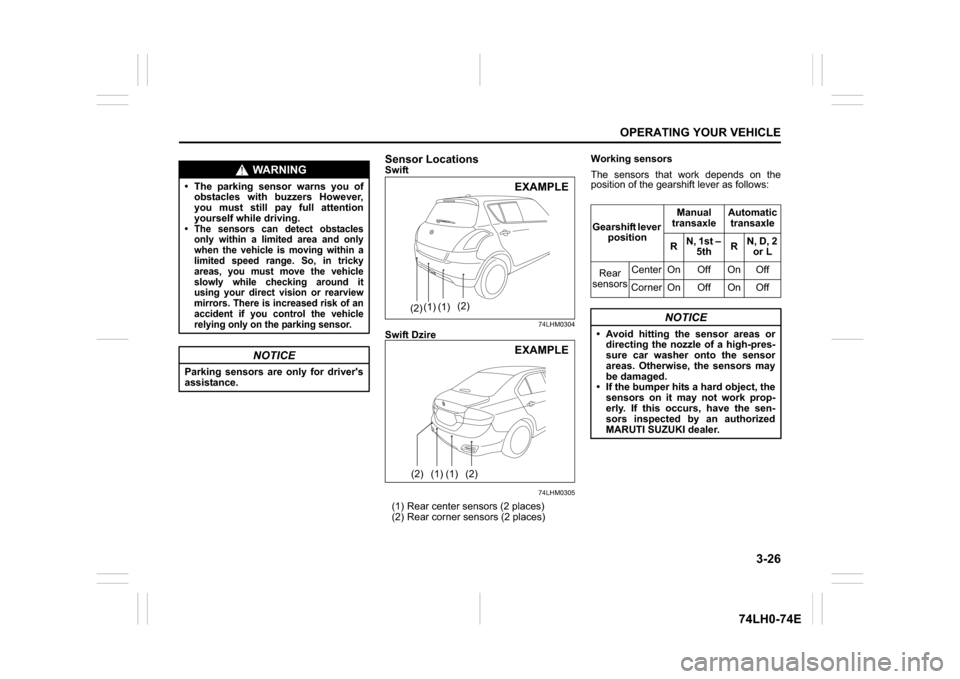
Sensor LocationsSwift
74LHM0304
Swift Dzire
74LHM0305
(1) Rear center sensors (2 places)
(2) Rear corner sensors (2 places) Working sensors
The sensors that work depends on the
position of the gearshift lever as follows:
WARNING
The parking sensor warns you of
obstacles with buzzers However,
you must still pay full attention
yourself while driving. The sensors can detect obstacles only within a limited area and only
when the vehicle is moving within a
limited speed range. So, in tricky
areas, you must move the vehicle
slowly while checking around it
using your direct vision or rearview
mirrors. There is increased risk of an
accident if you control the vehicle
relying only on the parking sensor.
NOTICE
Parking sensors are only for driver's
assistance.
EXAMPLE
(2)
(2)
(1) (1)
(2)
(2)
(1) (1)
EXAMPLE
Gearshift lever position Manual
transaxle Automatic
transaxle
R N, 1st –
5th R
N, D, 2or L
Re
ar
sensors Center On Off On Off
Corner On Off On Off
NOTICE
Avoid hitting the sensor areas or directing the nozzle of a high-pres-
sure car washer onto the sensor
areas. Otherwise, the sensors may
be damaged.
If the bumper hits a hard object, the
sensors on it may not work prop-
erly. If this occurs, have the sen-
sors inspected by an authorized
MARUTI SUZUKI dealer.
Page 112 of 336
3-27OPERATING YOUR VEHICLE
74LH0-74E
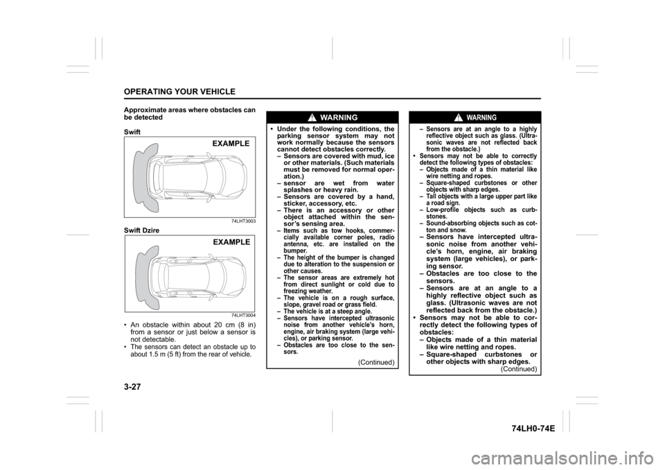
Approximate areas where obstacles can
be detected
Swift
74LHT3003
Swift Dzire
74LHT3004
An obstacle within about 20 cm (8 in)
from a sensor or just below a sensor is
not detectable. The sensors can detect an obstacle up to
about 1.5 m (5 ft) from the rear of vehicle. EXAMPLE EXAMPLE
WA R N I N G
Under the following conditions, the
parking sensor system may not
work normally because the sensors
cannot detect obstacles correctly.
– Sensors are covered with mud, ice
or other materials. (Such materials
must be removed for normal oper-
ation.)
– sensor are wet from water
splashes or heavy rain.
– Sensors are covered by a hand,
sticker, accessory, etc.
– There is an accessory or other
object attached within the sen-
sor’s sensing area.– Items such as tow hooks, commer-
cially available corner poles, radio
antenna, etc. are installed on the
bumper.
– The height of the bumper is changed
due to alteration to the suspension or
other causes.
– The sensor areas are extremely hot
from direct sunlight or cold due to
freezing weather.
– The vehicle is on a rough surface,
slope, gravel road or grass field.
– The vehicle is at a steep angle.
– Sensors have intercepted ultrasonic
noise from another vehicle’s horn,
engine, air braking system (large vehi-
cles), or parking sensor.
– Obstacles are too close to the sen-
sors.
(Continued)
WARNING
– Sensors are at an angle to a highly
reflective object such as glass. (Ultra-
sonic waves are not reflected back
from the obstacle.)
Sensors may not be able to correctly
detect the following types of obstacles:
– Objects made of a thin material like
wire netting and ropes.
– Square-shaped curbstones or other
objects with sharp edges.
– Tall objects with a large upper part like
a road sign.
– Low-profile objects such as curb-
stones.
– Sound-absorbing objects such as cot-
ton and snow.– Sensors have intercepted ultra-
sonic noise from another vehi-
cle’s horn, engine, air braking
system (large vehicles), or park-
ing sensor.
– Obstacles are too close to the
sensors.
– Sensors are at an angle to a
highly reflective object such as
glass. (Ultrasonic waves are not
reflected back from the obstacle.)
Sensors may not be able to cor-
rectly detect the following types of
obstacles:
– Objects made of a thin material
like wire netting and ropes.
– Square-shaped curbstones or
other objects with sharp edges.
(Continued)
Page 113 of 336
3-28
OPERATING YOUR VEHICLE
74LH0-74E
NOTE: Thin poles or obstacles lower than the sen-
sors may become undetectable as the
vehicle moves closer to them even if they
have been detected from longer distances.
The system may calculate the distance to
a road sign or similar obstacle to be shorter
than the actual dist
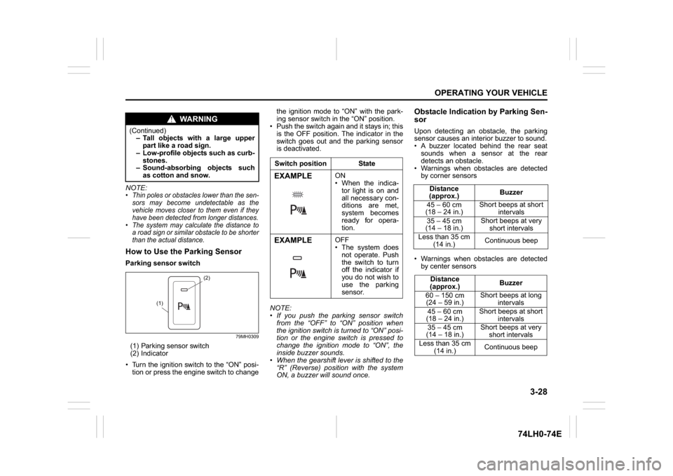
ance.How to Use the Parking SensorParking sensor switch
79MH0309
(1) Parking sensor switch
(2) Indicator
Turn the ignition switch to the “ON” posi-
tion or press the engine switch to changethe ignition mode to “ON” with the park-
ing sensor switch in the “ON” position.
Push the switch again and it stays in; this
is the OFF position. The indicator in the
switch goes out and the parking sensor
is deactivated.
NOTE:
If you push the parking sensor switch
from the “OFF” to “ON” position when
the ignition switch is turned to “ON” posi-
tion or the engine switch is pressed to
change the ignition mode to “ON”, the
inside buzzer sounds.
When the gearshift lever is shifted to the
“R” (Reverse) position with the system
ON, a buzzer will sound once.
Obstacle Indication by Parking Sen-
sorUpon detecting an obstacle, the parking
sensor causes an interior buzzer to sound.
A buzzer located behind the rear seat
sounds when a sensor at the rear
detects an obstacle.
Warnings when obstacles are detected
by corner sensors
Warnings when obstacles are detected
by center sensors
WA R N I N G
(Continued)
– Tall objects with a large upper
part like a road sign.
– Low-profile objects such as curb-
stones.
– Sound-absorbing objects such
as cotton and snow.
(2)
(1)
Switch position StateEXAMPLE
ON
When the indica-
tor light is on and
all necessary con-
ditions are met,
system becomes
ready for opera-
tion.
EXAMPLE
OFF
The system does
not operate. Push
the switch to turn
off the indicator if
you do not wish to
use the parking
sensor.
Distance
(approx.)Buzzer
45 – 60 cm
(18 – 24 in.)Short beeps at short
intervals
35 – 45 cm
(14 – 18 in.)Short beeps at very
short intervals
Less than 35 cm
(14 in.)Continuous beep
Distance
(approx.)Buzzer
60 – 150 cm
(24 – 59 in.)Short beeps at long
intervals
45 – 60 cm
(18 – 24 in.)Short beeps at short
intervals
35 – 45 cm
(14 – 18 in.)Short beeps at very
short intervals
Less than 35 cm
(14 in.)Continuous beep
Page 114 of 336
3-29OPERATING YOUR VEHICLE
74LH0-74E
Warning and Indicator MessagesIf there is a problem or warning regarding
the parking sensor system, a buzzer and
the status of the indicator on the parking
sensor inform it. Follow its instruction.
The buzzer sounds intermittently. The
indicated sensor is contaminated. Wipe
it clean with a soft cloth. If the buzzer
does not stop after wiping, there may be
problem with the parking sensor system.
Have your vehicle inspected by an
authorized MARUTI SUZUKI dealer.The indicator does not come on when the
parking sensor switch is pressed. The indica-
tor goes off while operating. There may be a
problem with the parking sensor system,
Have your vehicle inspected by an authorized
MARUTI SUZUKI dealer.Braking
60G165S
The distance needed to bring any vehicle
to a halt increases with the speed of the
vehicle. The braking distance needed, for
example, at 60 km/h (37 mph) will be
approximately 4 times greater than the
braking distance needed at 30 km/h (19
mph). Start to brake the vehicle when there
is plenty of distance between your vehicle
and the stopping point, and slow down
gradually.
Power-Assisted Brakes
(if equipped)Your vehicle has power-assisted brakes. If
power assistance is lost due to a stalled
engine or other failures, the system is still
fully operational on reserve power and you
can bring the vehicle to a complete stop by
pressing the brake pedal once and holding
it down. The reserve power is partly used
up when you depress the brake pedal and
reduces each time the pedal is pressed.
Apply smooth and even pressure to the
pedal. Do not pump the pedal.Brake Assist System (if equipped)When you slam the brakes on, the brake
assist system judges as an emergency
stop and provides more powerful braking
for a driver who cannot hold down the
brake pedal firmly.
NOTE:
If you quickly and forcefully depress the
brakes, you may hear a clicking sound in
the brake pedal. This is normal and indi-
cates that the brake assist system is acti-
vated properly.
WA R N I N G
If water gets into the brake drums,
brake performance may become poor
and unpredictable. After driving
through water or washing the under-
side of the vehicle, test the brakes
while driving at a slow speed to see if
they have maintained their normal
effectiveness. If the brakes are less
effective than normal, dry them by
repeatedly applying the brakes while
driving slowly until the brakes have
regained their normal effectiveness.
WA R N I N G
Even without reserve power in the
brake system, you can still stop the
vehicle by pressing the brake pedal
harder than normally required. How-
ever, the stopping distance may be
longer.