wheel SUZUKI SWIFT 2017 5.G Owner's Manual
[x] Cancel search | Manufacturer: SUZUKI, Model Year: 2017, Model line: SWIFT, Model: SUZUKI SWIFT 2017 5.GPages: 336, PDF Size: 6.24 MB
Page 122 of 336
4-5DRIVING TIPS
67LH3-74E
If Your Vehicle Gets StuckIf your vehicle gets stuck in snow, mud, or
sand, follow the directions below:
1) Shift the transaxle back and forthbetween a forward range (or first gear
for manual transaxle) and reverse. This
will create a rocking motion which may
give you enough momentum to free the
vehicle. Press gently on the accelerator
to keep wheel spinning to a minimum
wheel rpm. Remove your foot from the
accelerator while shifting.
Do not race the engine. Excessive
wheel spin will cause the tires to dig
deeper, making it more difficult to free
the vehicle.
2) If your vehicle remains stuck after a few
minutes of rocking, we recommend you
to consult your authorised Maruti
Suzuki workshop or a roadside assis-
tance service. If a towing service is not
available in an emergency, your vehicle
may be temporarily towed by a towing
cable or chain secured to the towing
hook either on the front of the vehicle or
on the rear of the vehicle. Refer to
“Frame Hooks” in the “OTHER CON-
TROLS AND EQUIPMENT” section.
Driving on Wet Roads
WA R N I N G
Do not allow anyone to stand near
the vehicle when you are rocking it,
and do not spin the wheels faster
than an indicated 40 km/h on the
speedometer. Perso nal injury and/or
vehicle damage may result from spin-
ning the wheels too fast.
NOTICE
Do not continue rocking the vehicle
for more than a few minutes. Pro-
longed rocking can cause engine
overheating or transaxle damage.
NOTICE
When driving on wet roads, avoid driving through large amount of
standing water on the road. Large
amount of water entering the
engine compartment may cause
damage to the engine and or elec-
trical components.
If stuck in deep water, do not start the engine.
Water is incompressible substance, water inside engine is harmful to
the engine.
WA R N I N G
In addition to following the driving
tips in this section, it is important to
observe the following precautions.
Make sure your tires are in good
condition and always maintain the
specified tire pressure. Refer to
“Tires” in the “INSPECTION AND
MAINTENANCE” section for
details.
Do not use tires other than those
specified by MARUTI SUZUKI.
Never use different sizes or types
of tires on the front and rear
wheels. For information regarding
the specified tires, refer to the Tire
Information Label located on the
driver’s door lock pillar.
Never use oversized tires or spe- cial shock absorbers and springs
to raise (jack up) your vehicle. This
will change the handling character-
istics. Oversized tires may also rub
against the vehicle body over
bumps, causing vehicle damage or
tire failure.
After driving through water, test the brakes while driving at a slow
speed to see if they have main-
tained their normal effectiveness. If
they are less effective than normal,
dry them by repeatedly applying
the brakes while driving slowly
until the brakes have regained their
normal effectiveness.
Page 135 of 336
5-8
OTHER CONTROLS AND EQUIPMENT
74LH0-74E
You can use the air conditioning switch (6)
to manually turn the air conditioner on or off
according to your preference. When you
turn the air conditioning switch off, the cli-
mate control system cannot lower the inside
temperature below outside temperature.
To turn the climate control system off, push
the “OFF” switch (7).
NOTE:
If the “AUTO” on the display blinks, there is
a problem in the heating system and/or air
conditioning system. You should have the
system inspected by an authorized MAR-
UTI SUZUKI dealer.
NOTE:
To find the temperature at which you are
most comfortable, start with the 25°C
(75°F) setting.
If you turn the temperature selector (1)
until “HI” or “LO” appears on the display,
the climate control system will operate at
maximum heating or cooling and the
blower will run at full speed.
To avoid blowing cold air in cold weather
or hot air in hot weather, the system will
delay turning on the blower until warmed
or chilled air is available.
If your vehicle has been left in the sun
with the windows closed, it will cool
faster if you open the windows briefly. Even under the automatic operation, you
can set individual selectors to the man-
ual mode. The manually selected func-
tions are maintained, and the other
functions remain under automatic opera-
tion.
To return the blower speed selector (2),
air intake selector (3), and air flow selec-
tor (4) to automatic operation, push the
“AUTO” switch (8).
74LHT0510
Be careful not to cover the interior tem-
perature sensor (10) located between the
steering wheel and the climate control
panel, or the solar sensor (11) located at
the top of the driver’s side dashboard.
These sensors are used by the automatic
system to regulate temperature.
Even if the engine is turned OFF, the
temperature Setting remains in the
memory.
Manual operationYou can manually control the climate con-
trol system. Set the selectors to the
desired positions.
74LHT0509
NOTE:
If you need maximum defrosting:
push the defrost switch (5) to turn on the
defroster (the air conditioning system will
come on and the “FRESH AIR” mode will
be selected automatically),
set the blower speed selector to HIGH,
adjust the temperature selector to the
“HI” indication on the display, and
adjust the side outlets so the air blows
on the side windows.MaintenanceIf you do not use the air conditioner for a
long period, such as during winter, it may
not give the best performance when you
start using it again. To help maintain opti-
(10)(11)
EXAMPLE
EXAMPLE
Folding Rear Seats: 3
Page 161 of 336
5-34
OTHER CONTROLS AND EQUIPMENT
74LH0-74E
Remote Audio Controls
(if equipped)Controlling of basic functions of the audio
system is available using the switches on
the steering wheel.
Adjusting the volume
To increase the volume, hold down “+” of
the VOL switch (1). The volume will keep
on being increased until the switch is
released.
To decrease the volume, hold down “-” of
the VOL switch (1). The volume will keep
on being decreased until the switch is
released.
To mute the sound, press the switch (2).
Selecting the mode
Press the switch (3).
Each time the button is pressed, the mode
will change as follows:It is possible to turn on the audio system by
pressing the switch (3).
Selecting the radio station (FM1, FM2,
AM mode)
To select the next preset station, press
“ ” of the switch (4) only for a moment.
To select the previous preset station,
press “ ” of the switch (4) only for a
moment.
To scan a higher frequency radio station,
press “ ” of the switch (4) for 1 second
or longer.
To scan a lower frequency radio station,
press “ ” of the switch (4) for 1 second
or longer.
Selecting the track (CD, USB (iPod
®),®
audio mode) To skip to the next track, press “ ” of the
switch (4) only for a moment.
To skip to the previous track, press “ ” of
the switch (4) twice only for a moment.
When the switch (4) is pushed down
once only for a moment, the track cur-
rently being played will start from the
beginning again.
Fast forwarding/Rewinding a track
To fast forward, press “ ” of the switch
(4) for 1 second or longer.
To fast rewind, press “ ” of the switch (4)
for 1 second or longer.
Anti-Theft Feature(1) VOL PUSH POWER knob
(2) Preset buttons ([1] to [6])
(3) Up button
(4) TUNE FOLDER PUSH SOUND knob
(2)
(3)
(1)
(4)
FM1 (Radio)
FM2 (Radio)
CD® audio (if equipped)
AUX (if equipped)
USB (iPod
®) (if equipped)
AM (Radio)
<
<<<
<
<
<<
(1)
B S U
CD
2
3 4 5 6
S
EEK/TRACK
AS
AMFM RPT
RDM
DISP
PUSHSOUND
TUNE/FLD
VOLPWRPUSH
11
MENU
(3)(4)
(2)
Page 163 of 336
5-36
OTHER CONTROLS AND EQUIPMENT
74LH0-74E
Battery InstallationInstall a lithium battery (CR2025) with the
poles facing the correct direction.
Battery replacement timing
When battery power is depleted, the but-
ton may not be operable. If the remote
controller does not operate, replace the
battery and check the operation.
Caution on battery
Be sure to follow the instructions to pre-
vent battery leakage, over-heating, igni-
tion or explosion.If battery leakage has occurred, wipe the
container first then install a new battery. If
the battery solution contacts the skin, wash
off with water completely.
Caution on Remote Controller
Do not leave the remote controller in an
area exposed to direct sunlight, such as
on the dashboard or steering wheel. The
remote controller may deform because
of the heat, (Be especially careful of the
dashboard exposed to direct sunlight in
the summer, as it will become extremely
hot).
When the vehicle is parked in an area
exposed to direct sunlight, Ensure the
remote controller is placed in an area not
exposed to direct sunlight. For example:
Glove box.
Under direct sunlight, signal reception
from the remote controller weakens. If
this happens, hold the remote controller
close to the signal receptor on the front
panel.
WA R N I N G
Do not expose the battery to flame.
Do not short circuit, disassemble,
or heat the battery.
Do not charge the battery.
Use the specified type battery.
Keep the button-shaped battery
away from children to prevent acci-
dental swallowing.
If the battery is swallowed, contact a
doctor immediately.
CAUTION
Install the battery with the poles
facing the correct direction.
When not in use for a long period
of time, or if the battery is dead,
remove the battery from the remote
controller.
Page 181 of 336
5-54
OTHER CONTROLS AND EQUIPMENT
74LH0-74E
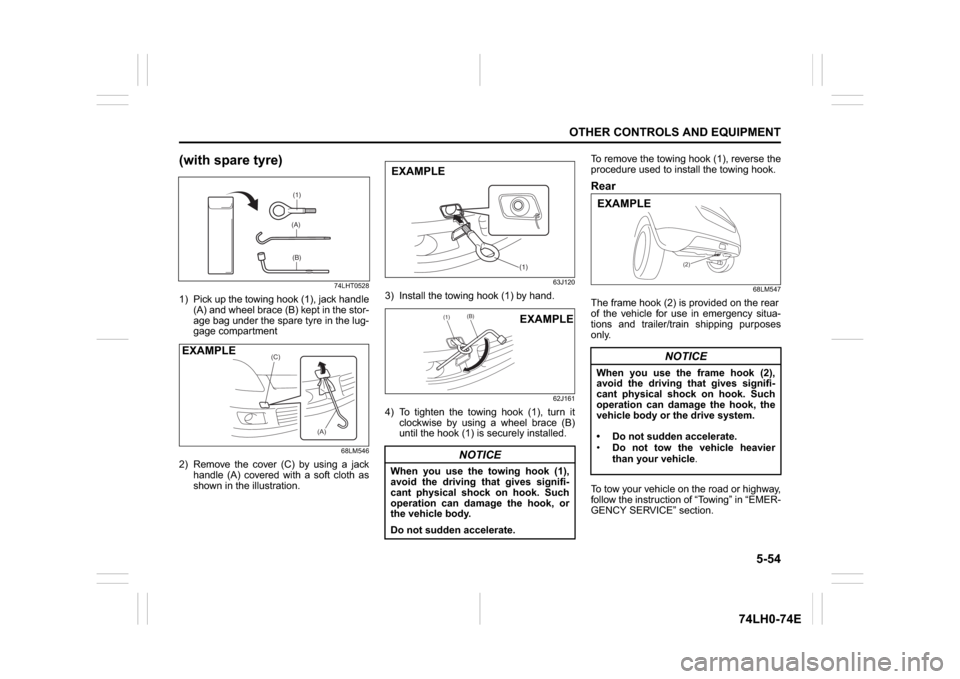
(with spare tyre)
74LHT0528
1) Pick up the towing hook (1), jack handle
(A) and wheel brace (B) kept in the stor-
age bag under the spare tyre in the lug-
gage compartment
68LM546
2) Remove the cover (C) by using a jack
handle (A) covered with a soft cloth as
shown in the illustration.
63J120
3) Install the towing hook (1) by hand.
62J161
4) To tighten the towing hook (1), turn it
clockwise by using a wheel brace (B)
until the hook (1) is securely installed.To remove the towing hook (1), reverse the
procedure used to install the towing hook.
Rear
68LM547
The frame hook (2) is provided on the rear
of the vehicle for use in emergency situa-
tions and trailer/train shipping purposes
only.
To tow your vehicle on the road or highway,
follow the instruction of “Towing” in “EMER-
GENCY SERVICE” section.
(1)(A)(B)
(C)
(A)
EXAMPLE
NOTICE
When you use the towing hook (1),
avoid the driving that gives signifi-
cant physical shock on hook. Such
operation can damage the hook, or
the vehicle body.
Do not sudden accelerate.
(1)
EXAMPLE
(1)
(B)
EXAMPLE
NOTICE
When you use the frame hook (2),
avoid the driving that gives signifi-
cant physical shock on hook. Such
operation can damage the hook, the
vehicle body or the drive system.
Do not sudden accelerate.
Do not tow the vehicle heavier
than your vehicle.
(2)
EXAMPLE
Page 186 of 336
6-3VEHICLE LOADING AND TOWING
74LH0-74E
Additional Trailer Towing Warnings
WA R N I N G
Connect trailer lights and hook up
safety chains every time you tow.
NOTICE
Because towing a trailer puts addi-
tional stress on your vehicle, more
frequent maintenance will be
required than under normal driving
conditions.
WA R N I N G
Your vehicle will handle differently
when towing a trailer. For your safety
and the safety of others, you should
observe the following precautions:
Practice turning, stopping, and
reversing before you begin towing
in traffic. Do not tow in traffic until
you are confident that you can han-
dle the vehicle and trailer safely.
Never exceed towing speed limits
or 80 km/h (50 mph), whichever is
lower.
Never drive at a speed that causes
shaking or swaying of the trailer. If
you notice even the slightest sign
of shaking or swaying, slow down.
When roads are wet, slippery or
rough, drive at a slower speed than
you would on dry, smooth roads.
Failure to slow down when road
conditions are bad can result in
loss of control.
Always have someone guide you
when reversing.
Allow adequate stopping distance.
Stopping distance is increased
when you tow a trailer. For each 16
(Continued)
WA R N I N G
(Continued)
km/h (10 mph) of speed, allow at
least one vehicle and trailer length
between you and the vehicle ahead.
Follow at a greater distance if roads
are wet or slippery.
If the trailer has over-run brakes,
apply the brakes gradually to avoid
snatching caused by the trailer
wheels locking.
Slow down before corners and
maintain a steady speed while cor-
nering. Deceleration or accelera-
tion while cornering can result in
loss of control. Remember that a
larger than normal turning radius is
needed because the trailer wheels
will be closer than vehicle wheels
to the inside of the turn.
Avoid sudden acceleration and
stopping of the vehicle. Do not
make quick maneuvers unless they
are necessary.
Slow down in cross winds and be
prepared for gusts of wind from
large passing vehicles.
(Continued)
Page 187 of 336
6-4
VEHICLE LOADING AND TOWING
74LH0-74E
60A186
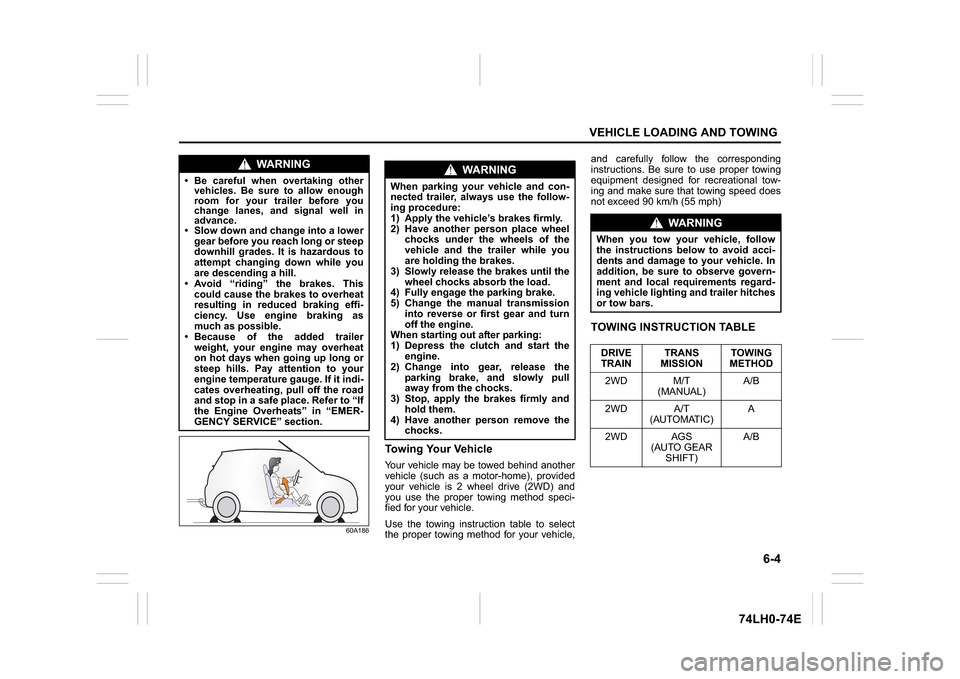
Towing Your VehicleYour vehicle may be towed behind another
vehicle (such as a motor-home), provided
your vehicle is 2 wheel drive (2WD) and
you use the proper towing method speci-
fied for your vehicle.
Use the towing instruction table to select
the proper towing method for your vehicle,and carefully follow the corresponding
instructions. Be sure to use proper towing
equipment designed for recreational tow-
ing and make sure that towing speed does
not exceed 90 km/h (55 mph)
TOWING INSTRUCTION TABLE
WA R N I N G
Be careful when overtaking other
vehicles. Be sure to allow enough
room for your trailer before you
change lanes, and signal well in
advance. Slow down and change into a lower
gear before you reach long or steep
downhill grades. It is hazardous to
attempt changing down while you
are descending a hill.
Avoid “riding” the brakes. This
could cause the brakes to overheat
resulting in reduced braking effi-
ciency. Use engine braking as
much as possible.
Because of the added trailer
weight, your engine may overheat
on hot days when going up long or
steep hills. Pay attention to your
engine temperature gauge. If it indi-
cates overheating, pull off the road
and stop in a safe place. Refer to “If
the Engine Overheats” in “EMER-
GENCY SERVICE” section.
WA R N I N G
When parking your vehicle and con-
nected trailer, always use the follow-
ing procedure:
1) Apply the vehicle’s brakes firmly.
2) Have another person place wheel
chocks under the wheels of the
vehicle and the trailer while you
are holding the brakes.
3) Slowly release the brakes until the
wheel chocks absorb the load.
4) Fully engage the parking brake.
5) Change the manual transmission
into reverse or first gear and turn
off the engine.
When starting out after parking:
1) Depress the clutch and start the
engine.
2) Change into gear, release the
parking brake, and slowly pull
away from the chocks.
3) Stop, apply the brakes firmly and
hold them.
4) Have another person remove the
chocks.
WA R N I N G
When you tow your vehicle, follow
the instructions below to avoid acci-
dents and damage to your vehicle. In
addition, be sure to observe govern-
ment and local requirements regard-
ing vehicle lighting and trailer hitches
or tow bars.
DRIVE
TRAINTRANS
MISSIONTOWING
METHOD
2WD M/T
(MANUAL)A/B
2WD A/T
(AUTOMATIC)A
2WD AGS
(AUTO GEAR
SHIFT)A/B
Page 188 of 336

6-5VEHICLE LOADING AND TOWING
74LH0-74E
A: 2WD VEHICLES WITH MANUAL
TRANSAXLE OR AUTOMATIC
TRANSAXLE OR AUTO GEAR
SHIFT1) Secure the front wheels on a towing
dolly according to the instructions pro-
vided by the dolly manufacturer.
2) Release the parking brake.
NOTICE
The steering column is not strong
enough to withstand shocks trans-
mitted from the front wheels during
towing. Always unlock the steering
wheel before towing. TOWING METHOD AFROM THE FRONT:
FRONT WHEELS ON A DOLLY
AND REAR WHEELS ON THE GROUND
B: 2WD VEHICLES WITH MANUAL TRANSAXLE OR AUTO GEAR SHIFT1) Shift the manual transaxle lever into neutral.
2) Turn the ignition key to the “ACC” position or change the ignition mode to the “ACC” to
unlock the steering wheel.
3) Release the parking brake.
ACC
N
TOWING METHOD BFROM THE FRONT:
FRONT WHEELS ON THE GROUND
Page 195 of 336
7-4
INSPECTION AND MAINTENANCE
74LH0-74E
4-3.
Transmission Oil (Manual / Auto Gear Shift)
l
l
l
l
l
l
l
l
l
l
Replace at 1,60,000 km or 10 years whichever comes first
4-4. Automatic Transmission Fluid (Level, Leakage) Replace at 1,65,000 km or 11years whichever comes first
4-5.
Hose, Automatic Transmission Fluid
l
l
l
l
l
l
l
l
l
l
Drive shaft
5-1.
Drive shaft boot (boot damage)
-
l
l
l
l
l
l
l
l
l
BRAKE
6-1.
Brake Fluid (Level, Leakage)
I
I
I
R
I
R
I
R
I
R
6-2. Brake pedal (pedal - carpet clearance) I I I I I I I I I I
6-3.
Parking brake lever and cable (Play, damage)
I
I
I
I
I
I
I
I
I
I
6-4. Brake disc and pad (Wear) – I I I I I I I I I
6-5.
Brake drum and shoes (Wear)
–
–
I
I
I
I
I
I
I
I
6-6.Master cylinder, wheel cylinder, caliper piston
(Fluid leakage, boot/seal damage)IIIIIIIIII
6-7.
Brake hoses and pipes (Fluid leakage, damage)
I
I
I
I
I
I
I
I
I
I
WHEEL
7-1.
Tires (air pressure, abnormal wear, crack and rotation)
I
I&O
I&O
I&O
I&O
I&O
I&O
I&O
I&O
I&O
7-2. Wheels (Damage) I I I I I I I I I I
7-3.
Front/Rear wheel bearing (Loose, damage)
I
I
I
I
I
I
I
I
I
I
FRONT / REAR SUSPENSION
8-1.
Suspension strut (Oil leakage, damage)
I
I
I
I
I
I
I
I
I
I
8-2. Suspension arms / Knuckle support (Loose, damage) – I I I I I I I I I
8-3.
Rear spring (Damage)
I
I
I
I
I
I
I
I
I
I
8-4. Shock absorbers (Oil leakage, damage) I I I I I I I I I I
8-5.
All bolts and nuts (Loose)
–
T
T
T
T
T
T
T
T
T
8-6. Suspension arms and torsion rods – I I I I I I I I I
STEERING
9-1. Steering wheel (Play, loose) I I I I I I I I I IInterval: This interval should be judged by odometer reading
or months, whichever comes first.
FREE INSPECTION
PERIODIC MAINTENANCE AT COST
km (x1000)
1
5
10
20
30
40
50
60
70
80
months
1
6
12
24
36
48
60
72
84
96
Drive Belt: 1, 2
Engine Oil and Filter: 1, 2
Page 208 of 336
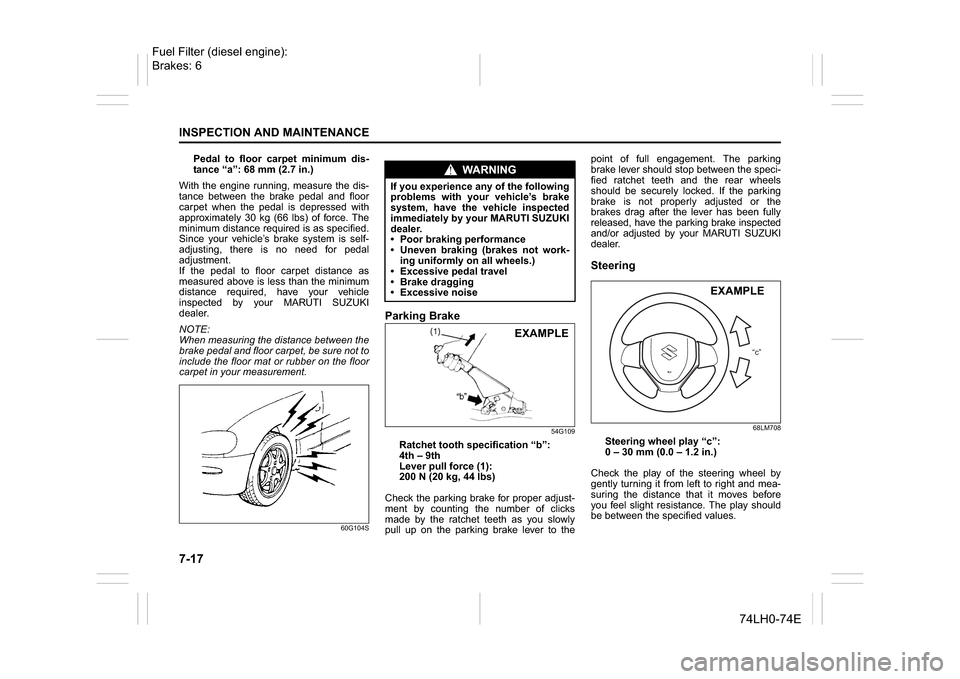
7-17INSPECTION AND MAINTENANCE
74LH0-74E
Pedal to floor carpet minimum dis-
tance “a”: 68 mm (2.7 in.)
With the engine running, measure the dis-
tance between the brake pedal and floor
carpet when the pedal is depressed with
approximately 30 kg (66 lbs) of force. The
minimum distance required is as specified.
Since your vehicle’s brake system is self-
adjusting, there is no need for pedal
adjustment.
If the pedal to floor carpet distance as
measured above is less than the minimum
distance required, have your vehicle
inspected by your MARUTI SUZUKI
dealer.
NOTE:
When measuring the distance between the
brake pedal and floor carpet, be sure not to
include the floor mat or rubber on the floor
carpet in your measurement.
60G104S
Parking Brake
54G109
Ratchet tooth specification “b”:
4th – 9th
Lever pull force (1):
200 N (20 kg, 44 lbs)
Check the parking brake for proper adjust-
ment by counting the number of clicks
made by the ratchet teeth as you slowly
pull up on the parking brake lever to thepoint of full engagement. The parking
brake lever should stop between the speci-
fied ratchet teeth and the rear wheels
should be securely locked. If the parking
brake is not properly adjusted or the
brakes drag after the lever has been fully
released, have the parking brake inspected
and/or adjusted by your MARUTI SUZUKI
dealer.
Steering
68LM708
Steering wheel play “c”:
0 – 30 mm (0.0 – 1.2 in.)
Check the play of the steering wheel by
gently turning it from left to right and mea-
suring the distance that it moves before
you feel slight resistance. The play should
be between the specified values.
WA R N I N G
If you experience any of the following
problems with your vehicle’s brake
system, have the vehicle inspected
immediately by your MARUTI SUZUKI
dealer.
Poor braking performance
Uneven braking (brakes not work-
ing uniformly on all wheels.)
Excessive pedal travel
Brake dragging
Excessive noise
EXAMPLE
“c”
EXAMPLE
Fuel Filter (diesel engine):
Brakes: 6