Gear SUZUKI SWIFT 2017 5.G Owner's Guide
[x] Cancel search | Manufacturer: SUZUKI, Model Year: 2017, Model line: SWIFT, Model: SUZUKI SWIFT 2017 5.GPages: 336, PDF Size: 6.24 MB
Page 130 of 336
5-3OTHER CONTROLS AND EQUIPMENT
74LH0-74E
Temperature-controlled air comes out of
the floor outlets and cooler air comes out
of the center and side outlets. When the
temperature selector (1) is in the fully
COLD position or fully HOT position, how-
ever, the air from the floor outlets and the
air from the center and side outlets will be
the same temperature.
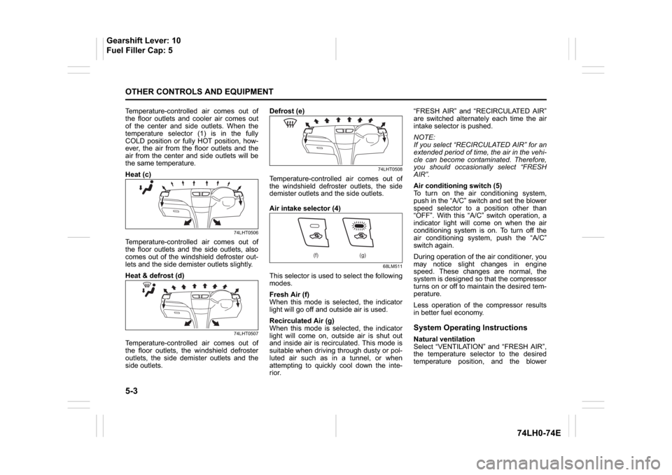
Heat (c)
74LHT0506
Temperature-controlled air comes out of
the floor outlets and the side outlets, also
comes out of the windshield defroster out-
lets and the side demister outlets slightly.
Heat & defrost (d)
74LHT0507
Temperature-controlled air comes out of
the floor outlets, the windshield defroster
outlets, the side demister outlets and the
side outlets.Defrost (e)
74LHT0508
Temperature-controlled air comes out of
the windshield defroster outlets, the side
demister outlets and the side outlets.
Air intake selector (4)
68LM511
This selector is used to select the following
modes.
Fresh Air (f)
When this mode is selected, the indicator
light will go off and outside air is used.
Recirculated Air (g)
When this mode is selected, the indicator
light will come on, outside air is shut out
and inside air is recirculated. This mode is
suitable when driving through dusty or pol-
luted air such as in a tunnel, or when
attempting to quickly cool down the inte-
rior.“FRESH AIR” and “RECIRCULATED AIR”
are switched alternately each time the air
intake selector is pushed.
NOTE:
If you select “RECIRCULATED AIR” for an
extended period of time, the air in the vehi-
cle can become contaminated. Therefore,
you should occasionally select “FRESH
AIR”.
Air conditioning switch (5)
To turn on the air conditioning system,
push in the “A/C” switch and set the blower
speed selector to a position other than
“OFF”. With this “A/C” switch operation, a
indicator light will come on when the air
conditioning system is on. To turn off the
air conditioning system, push the “A/C”
switch again.
During operation of the air conditioner, you
may notice slight changes in engine
speed. These changes are normal, the
system is designed so that the compressor
turns on or off to maintain the desired tem-
perature.
Less operation of the compressor results
in better fuel economy.
System Operating InstructionsNatural ventilation
Select “VENTILATION” and “FRESH AIR”,
the temperature selector to the desired
temperature position, and the blower
(f) (g)
Gearshift Lever: 10
Fuel Filler Cap: 5
Page 187 of 336
6-4
VEHICLE LOADING AND TOWING
74LH0-74E
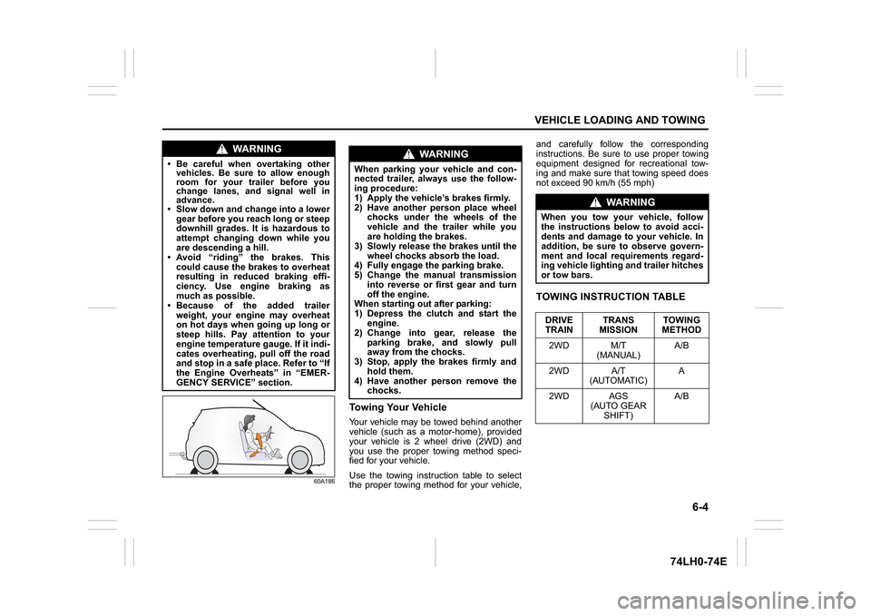
60A186
Towing Your VehicleYour vehicle may be towed behind another
vehicle (such as a motor-home), provided
your vehicle is 2 wheel drive (2WD) and
you use the proper towing method speci-
fied for your vehicle.
Use the towing instruction table to select
the proper towing method for your vehicle,and carefully follow the corresponding
instructions. Be sure to use proper towing
equipment designed for recreational tow-
ing and make sure that towing speed does
not exceed 90 km/h (55 mph)
TOWING INSTRUCTION TABLE
WA R N I N G
Be careful when overtaking other
vehicles. Be sure to allow enough
room for your trailer before you
change lanes, and signal well in
advance. Slow down and change into a lower
gear before you reach long or steep
downhill grades. It is hazardous to
attempt changing down while you
are descending a hill.
Avoid “riding” the brakes. This
could cause the brakes to overheat
resulting in reduced braking effi-
ciency. Use engine braking as
much as possible.
Because of the added trailer
weight, your engine may overheat
on hot days when going up long or
steep hills. Pay attention to your
engine temperature gauge. If it indi-
cates overheating, pull off the road
and stop in a safe place. Refer to “If
the Engine Overheats” in “EMER-
GENCY SERVICE” section.
WA R N I N G
When parking your vehicle and con-
nected trailer, always use the follow-
ing procedure:
1) Apply the vehicle’s brakes firmly.
2) Have another person place wheel
chocks under the wheels of the
vehicle and the trailer while you
are holding the brakes.
3) Slowly release the brakes until the
wheel chocks absorb the load.
4) Fully engage the parking brake.
5) Change the manual transmission
into reverse or first gear and turn
off the engine.
When starting out after parking:
1) Depress the clutch and start the
engine.
2) Change into gear, release the
parking brake, and slowly pull
away from the chocks.
3) Stop, apply the brakes firmly and
hold them.
4) Have another person remove the
chocks.
WA R N I N G
When you tow your vehicle, follow
the instructions below to avoid acci-
dents and damage to your vehicle. In
addition, be sure to observe govern-
ment and local requirements regard-
ing vehicle lighting and trailer hitches
or tow bars.
DRIVE
TRAINTRANS
MISSIONTOWING
METHOD
2WD M/T
(MANUAL)A/B
2WD A/T
(AUTOMATIC)A
2WD AGS
(AUTO GEAR
SHIFT)A/B
Page 188 of 336

6-5VEHICLE LOADING AND TOWING
74LH0-74E
A: 2WD VEHICLES WITH MANUAL
TRANSAXLE OR AUTOMATIC
TRANSAXLE OR AUTO GEAR
SHIFT1) Secure the front wheels on a towing
dolly according to the instructions pro-
vided by the dolly manufacturer.
2) Release the parking brake.
NOTICE
The steering column is not strong
enough to withstand shocks trans-
mitted from the front wheels during
towing. Always unlock the steering
wheel before towing. TOWING METHOD AFROM THE FRONT:
FRONT WHEELS ON A DOLLY
AND REAR WHEELS ON THE GROUND
B: 2WD VEHICLES WITH MANUAL TRANSAXLE OR AUTO GEAR SHIFT1) Shift the manual transaxle lever into neutral.
2) Turn the ignition key to the “ACC” position or change the ignition mode to the “ACC” to
unlock the steering wheel.
3) Release the parking brake.
ACC
N
TOWING METHOD BFROM THE FRONT:
FRONT WHEELS ON THE GROUND
Page 189 of 336
6-6
VEHICLE LOADING AND TOWING
74LH0-74E
NOTICE
After shifting the Auto Gear Shift
lever to the “N” position, always
check the gear position indicator in
the instrument cluster shows the “N”
position to make sure that the
transaxle is disengaged.
If the transaxle cannot be put in neu-
tral, turn the key from the “LOCK” to
the “ON” position, and move the
Auto Gear Shift lever from “N” to “D”,
“M” or “R”, then back to “N” again.
Then turn the key from the “ON” to
the “LOCK” position.
These procedures may help put the
transaxle in neutral. If the transaxle
still cannot be put in neutral, you can-
not tow the vehicle without using a
towing dolly.
Page 191 of 336
INSPECTION AND MAINTENANCE
INSPECTION AND MAINTENANCE
Maintenance Schedule ....................................................... 7-2
Periodic Maintenance Schedule ........................................ 7-2
Drive Belt ............................................................................. 7-6
Engine Oil and Filter ........................................................... 7-6
Engine Coolant .................................................................... 7-10
Air Cleaner ........................................................................... 7-11
Spark Plugs (Petrol Engine)................................................ 7-11
Gear Oil ................................................................................ 7-13
Clutch Pedal ........................................................................ 7-14
Fuel Filter (Diesel Engine) .................................................. 7-15
Brakes .................................................................................. 7-16
7
Steering ................................................................................ 7-17
Tires ...................................................................................... 7-18
Battery .................................................................................. 7-20
Fuses .................................................................................... 7-22
Bulb Replacement ............................................................... 7-24
Wiper Blades ....................................................................... 7-28
Windshield Washer Fluid ................................................... 7-30
Air Conditioning System .................................................... 7-30
74LH0-74E
Page 195 of 336
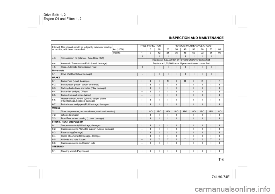
7-4
INSPECTION AND MAINTENANCE
74LH0-74E
4-3.
Transmission Oil (Manual / Auto Gear Shift)
l
l
l
l
l
l
l
l
l
l
Replace at 1,60,000 km or 10 years whichever comes first
4-4. Automatic Transmission Fluid (Level, Leakage) Replace at 1,65,000 km or 11years whichever comes first
4-5.
Hose, Automatic Transmission Fluid
l
l
l
l
l
l
l
l
l
l
Drive shaft
5-1.
Drive shaft boot (boot damage)
-
l
l
l
l
l
l
l
l
l
BRAKE
6-1.
Brake Fluid (Level, Leakage)
I
I
I
R
I
R
I
R
I
R
6-2. Brake pedal (pedal - carpet clearance) I I I I I I I I I I
6-3.
Parking brake lever and cable (Play, damage)
I
I
I
I
I
I
I
I
I
I
6-4. Brake disc and pad (Wear) – I I I I I I I I I
6-5.
Brake drum and shoes (Wear)
–
–
I
I
I
I
I
I
I
I
6-6.Master cylinder, wheel cylinder, caliper piston
(Fluid leakage, boot/seal damage)IIIIIIIIII
6-7.
Brake hoses and pipes (Fluid leakage, damage)
I
I
I
I
I
I
I
I
I
I
WHEEL
7-1.
Tires (air pressure, abnormal wear, crack and rotation)
I
I&O
I&O
I&O
I&O
I&O
I&O
I&O
I&O
I&O
7-2. Wheels (Damage) I I I I I I I I I I
7-3.
Front/Rear wheel bearing (Loose, damage)
I
I
I
I
I
I
I
I
I
I
FRONT / REAR SUSPENSION
8-1.
Suspension strut (Oil leakage, damage)
I
I
I
I
I
I
I
I
I
I
8-2. Suspension arms / Knuckle support (Loose, damage) – I I I I I I I I I
8-3.
Rear spring (Damage)
I
I
I
I
I
I
I
I
I
I
8-4. Shock absorbers (Oil leakage, damage) I I I I I I I I I I
8-5.
All bolts and nuts (Loose)
–
T
T
T
T
T
T
T
T
T
8-6. Suspension arms and torsion rods – I I I I I I I I I
STEERING
9-1. Steering wheel (Play, loose) I I I I I I I I I IInterval: This interval should be judged by odometer reading
or months, whichever comes first.
FREE INSPECTION
PERIODIC MAINTENANCE AT COST
km (x1000)
1
5
10
20
30
40
50
60
70
80
months
1
6
12
24
36
48
60
72
84
96
Drive Belt: 1, 2
Engine Oil and Filter: 1, 2
Page 196 of 336
7-5INSPECTION AND MAINTENANCE
74LH0-74E
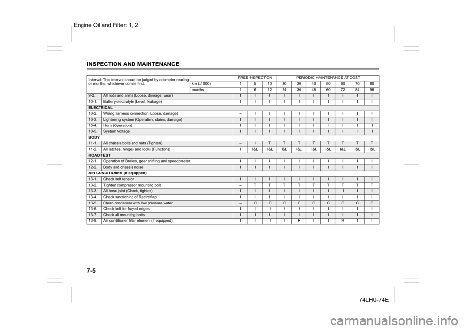
9-2.
All rods and arms (Loose, damage, wear)
I
I
I
I
I
I
I
I
I
I
10-1. Battery electrolyte (Level, leakage) I I I I I I I I I I
ELECTRICAL
10-2. Wiring harness connection (Loose, damage)
–
I I I I I I I I I10-3.
Lightening system (Operation, stains, damage)
I
I
I
I
I
I
I
I
I
I
10-4. Horn (Operation) I I I I I I I I I I
10-5.
System Voltage
I
I
I
I
I
I
I
I
I
I
BODY
11-1.
All chassis bolts and nuts (Tighten)
–
I
T
T
T
T
T
T
T
T
11-2. All latches, hinges and locks (Function)) I I&L I&L I&L I&L I&L I&L I&L I&L I&L
ROAD TEST12-1.
Operation of Brakes, gear shifting and speedometer
I
I
I
I
I
I
I
I
I
I
12-2.
Body and chassis noise
I
I
I
I
I
I
I
I
I
I
AIR CONDITIONER (If equipped)
13-1.
Check belt tension
I
I
I
I
I
I
I
I
I
I
13-2. Tighten compressor mounting bolt
–
T T T T T T T T T
13-3.
All hose joint (Check, tighten)
I
I
I
I
I
I
I
I
I
I
13-4. Check functioning of Recirc flap I I I I I I I I I I
13-5.
Clean condenser with low pressure water
–
C
C
C
C
C
C
C
C
C
13-6. Check belt for frayed edges I I I I I I I I I I
13-7.
Check all mounting bolts
I
I
I
I
I
I
I
I
I
I
13-8. Air conditioner filter element (if equipped) I I I I R I I R I I
Interval: This interval should be judged by odometer reading
or months, whichever comes first.
FREE INSPECTION
PERIODIC MAINTENANCE AT COST
km (x1000)
1
5
10
20
30
40
50
60
70
80
months
1
6
12
24
36
48
60
72
84
96
Engine Oil and Filter: 1, 2
Page 199 of 336

7-8
INSPECTION AND MAINTENANCE
74LH0-74E
Changing Engine Oil and FilterDrain the engine oil while the engine is still
warm.
56KN054
1) Remove the oil filler cap.
2) Place a drain pan under the drain plug.
3) Using a wrench, remove the drain plug
and drain out the engine oil.
60G306
Tightening torque for drain plug
Petrol engine:
35 Nm (3.5 kg-m, 25.3 lb-ft)
For Diesel Engine
60G306
For Diesel Engine
20 Nm (2.0 kg-m, 14.5 Ib-ft)4) Reinstall the drain plug and new gasket
(1). Tighten the plug with a wrench to
the specified torque.
CAUTION
The engine oil temperature may be
high enough to burn your fingers
when the drain plug is loosened. Wait
until the drain plug is cool enough to
touch with your bare hands.
Open Close
EXAMPLE
EXAMPLEEXAMPLE
WA R N I N G
New and used oil can be hazardous.
Children and pets may be harmed by
swallowing new or used oil. Keep
new and used oil and used oil filters
away from children and pets.
Continuous contact with used engine
oil may cause skin cancer laboratory
animals
Brief contact with used oil may irri-
tate skin.
To minimize your exposure to used
oil, wear a long-sleeve shirt and
moisture-proof gloves (such as
diswashing gloves) when changing
oil. If oil contacts your skin, wash
thoroughly with soap and water.
Launder any clothing or rags if wet
with oil.
Recycle or properly dispose of used
oil and filters.
Gear Oil: 10
Page 200 of 336
7-9INSPECTION AND MAINTENANCE
74LH0-74E
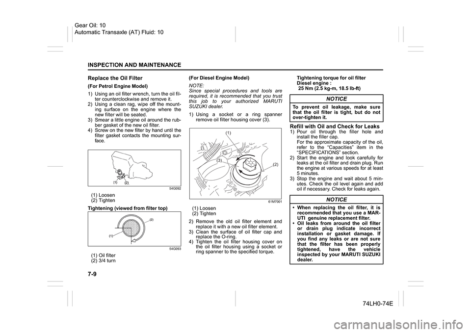
Replace the Oil Filter(For Petrol Engine Model)
1) Using an oil filter wrench, turn the oil fil-
ter counterclockwise and remove it.
2) Using a clean rag, wipe off the mount-
ing surface on the engine where the
new filter will be seated.
3) Smear a little engine oil around the rub-
ber gasket of the new oil filter.
4) Screw on the new filter by hand until the
filter gasket contacts the mounting sur-
face.
54G092
(1) Loosen
(2) Tighten
Tightening (viewed from filter top)
54G093
(1) Oil filter
(2) 3/4 turn(For Diesel Engine Model)
NOTE:
Since special procedures and tools are
required, it is recommended that you trust
this job to your authorized MARUTI
SUZUKI dealer.
1) Using a socket or a ring spanner
remove oil filter housing cover (3).
61M7001
(1) Loosen
(2) Tighten
2) Remove the old oil filter element and
replace it with a new oil filter element.
3) Clean the surface of oil filter cap and
replace the O-ring.
4) Tighten the oil filter housing cover on
the oil filter housing using a socket or
ring spanner to the specified torque.Tightening torque for oil filter
Diesel engine :
25 Nm (2.5 kg-m, 18.5 lb-ft)
Refill with Oil and Check for Leaks1) Pour oil through the filler hole and
install the filler cap.
For the approximate capacity of the oil,
refer to the “Capacities” item in the
“SPECIFICATIONS” section.
2) Start the engine and look carefully for
leaks at the oil filter and drain plug. Run
the engine at various speeds for at least
5 minutes.
3) Stop the engine and wait about 5 min-
utes. Check the oil level again and add
oil if necessary. Check for leaks again.
(1)
(3)
(2)
NOTICE
To prevent oil leakage, make sure
that the oil filter is tight, but do not
over-tighten it.
NOTICE
When replacing the oil filter, it is
recommended that you use a MAR-
UTI genuine replacement filter.
Oil leaks from around the oil filter
or drain plug indicate incorrect
installation or gasket damage. If
you find any leaks or are not sure
that the filter has been properly
tightened, have the vehicle
inspected by your MARUTI SUZUKI
dealer.
Gear Oil: 10
Automatic Transaxle (AT) Fluid: 10
Page 204 of 336
7-13INSPECTION AND MAINTENANCE
74LH0-74E
60D204
NOTE:
If your engine is equipped with the high
tension cord type ignition wiring and you
experience some firing problem of spark
plugs, such as, hard engine-starting, mis-
fire etc., the cause may be located not only
on spark plugs but also on deteriorated
ignition wirings (generally, used for more
than 80,000 km or five years). If spark plug
replacement does not solve the problem,
have the ignition wiring and other ignition
system inspected by your MARUTI
SUZUKI dealer.Gear OilManual Transaxle Oil / Auto Gear
Shift OilWhen adding gear oil, use gear oil with the
appropriate viscosity and grade.
We highly recommend you use:
"MARUTI SUZUKI GEAR OIL 75W-80" for
manual transaxle gear oil or Auto Gear
Shift Oil.
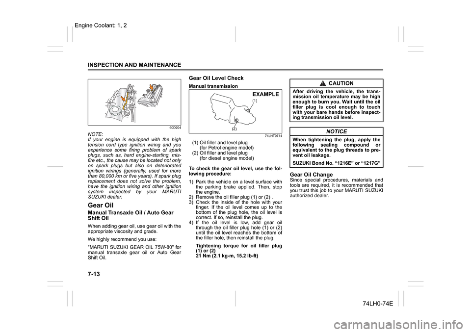
Gear Oil Level CheckManual transmission
74LHT0714
(1) Oil filler and level plug
(for Petrol engine model)
(2) Oil filler and level plug
(for diesel engine model)
To check the gear oil level, use the fol-
lowing procedure:
1) Park the vehicle on a level surface with
the parking brake applied. Then, stop
the engine.
2) Remove the oil filler plug (1) or (2) .
3) Check the inside of the hole with your
finger. If the oil level comes up to the
bottom of the plug hole, the oil level is
correct. If so, reinstall the plug.
4) If the oil level is low, add gear oil
through the oil filler plug hole (1) or (2)
until the oil level reaches the bottom of
the filler hole, then reinstall the plug.
Tightening torque for oil filler plug
(1) or (2)
21 Nm (2.1 kg-m, 15.2 lb-ft)
Gear Oil ChangeSince special procedures, materials and
tools are required, it is recommended that
you trust this job to your MARUTI SUZUKI
authorized dealer.
(1)
(2)
EXAMPLE
CAUTION
After driving the vehicle, the trans-
mission oil temperature may be high
enough to burn you. Wait until the oil
filler plug is cool enough to touch
with your bare hands before inspect-
ing transmission oil level.
NOTICE
When tightening the plug, apply the
following sealing compound or
equivalent to the plug threads to pre-
vent oil leakage.
SUZUKI Bond No. “1216E” or “1217G”
Engine Coolant: 1, 2