ignition SUZUKI SWIFT 2017 5.G Repair Manual
[x] Cancel search | Manufacturer: SUZUKI, Model Year: 2017, Model line: SWIFT, Model: SUZUKI SWIFT 2017 5.GPages: 336, PDF Size: 6.24 MB
Page 150 of 336
5-23OTHER CONTROLS AND EQUIPMENT
74LH0-74E
Notes on iPod
®
Supported iPod
®
® touch (5th generation)
® touch (4th generation)
® touch (3rd generation)
® touch (2nd generation)
® touch (1st generation)
® classic
® nano (7th generation)
® nano (6th generation)
® nano (5th generation)
® nano (4th generation)
® nano (3rd generation)
® nano (2nd generation)
® nano (1st generation)
® (5th generation)
iPhone® 6 Plus
iPhone® 6
iPhone® 5S
iPhone® 5
iPhone® 4S
iPhone® 4
iPhone® 3GS
iPhone® 3G
iPhone®
* Some functions may not be available
depending on the model of iPod
®.
*iPod
® is a trademark of Apple Inc., regis-
tered in the U.S. and other countries.
* iPhone® is a trademark of Apple Inc.,
registered in the U.S. and other coun-
tries.
* Apple is not responsible for the operation
of this device or its compliance with
safety and regulatory standards.iPod
® connection
Make sure to detach the iPod
® after
pressing the engine switch to change the
ignition mode to LOCK. The iPod® may
not be shut down when it is being con-
nected and may result in battery deple-
tion.
Please do not connect iPod
® accesso-
ries such as an iPod
® remote control or
headphones while connecting the iPod
®
with the unit. The unit may not operate
correctly.
AUX Function
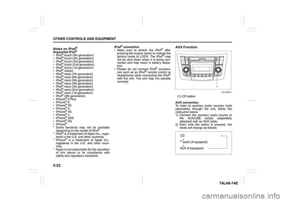
74LHT5011
(1) CD button
AUX connection
To listen to auxiliary audio sources (sold
separately) through the unit, follow the
instruction below.
1) Connect the auxiliary audio source to
the AUX/USB socket (separately
attached) with an AUX cable.
2) Each time the button is pressed, the
mode will change as follows:
B S U
CD
2
3 4 5 6
SEEK/TRACK
AS
AMFM RPT
RDM
DISP
PUSHSOUND
TUNE/FLD
VOL
PWRPUSH
11
MENU
(1)
CD® audio (if equipped)
AUX (if equipped)
Page 160 of 336
5-33OTHER CONTROLS AND EQUIPMENT
74LH0-74E
List of audio devices (List Audio)
Follow the instructions below to display the
names of the registered audio devices in
sequence.
1) Press the
® setup button (6).
The
® setup menu will be displayed.
2) Turn the TUNE FOLDER PUSH
SOUND knob (2) to select “Setup ”, and
press the knob (2) to determine the
selection.
3) Turn the TUNE FOLDER PUSH
SOUND knob (2) to select “List Audio”,
and press the knob (2) to determine the
selection. The names of registered
audio devices will be displayed in
sequence.
NOTE:
When selecting “Go Back”, the previous
menu will be displayed.
Passkey setting (Set Passkey)
Follow the instructions below to set the
security number (Passkey).
1) Press the
® setup button (6).
The
® setup menu will be displayed.
2) Turn the TUNE FOLDER PUSH
SOUND knob (2) to select “Setup ”, and
press the knob (2) to determine the
selection.
3) Turn the TUNE FOLDER PUSH
SOUND knob (2) to select “Passkey”,
and press the knob (2) to determine the
selection.
4) Turn the TUNE FOLDER PUSH
SOUND knob (2) to select “New Pass-key”, and press the knob (2) to deter-
mine the selection.
5) Press or turn the TUNE FOLDER
PUSH SOUND knob (2) to select “Con-
firm”.
6) Turn the TUNE FOLDER PUSH
SOUND knob (2) to select a number for
the first digit, and press the knob (2) to
determine the selection. Select and
determine numbers for the second,
third and fourth digits in order in the
same manner. When not entering up to
the eighth digit, enter blanks for the
successive digits.
7) Turn the TUNE FOLDER PUSH
SOUND knob (2) to determine the
passkey setting.
NOTE:
When selecting “Go Back”, the previous
menu will be displayed.
Deletion of audio device information
(Delete Audio)
Follow the instructions below to delete the
registered information of audio device.
1) Press the
® setup button (6).
The
® setup menu will be displayed.
2) Turn the TUNE FOLDER PUSH
SOUND knob (2) to select “Setup ”, and
press the knob (2) to determine the
selection.
3) Turn the TUNE FOLDER PUSH
SOUND knob (2) to select “List Audio”,
and press the knob (2) to determine the
selection.4) Turn the TUNE FOLDER PUSH
SOUND knob (2) to select an audio
device to be deleted, and press the
knob (2) to determine the selection.
5) Turn the TUNE FOLDER PUSH
SOUND knob (2) to select “Delete”, and
press the knob (2) to determine the
selection.
6) Turn the TUNE FOLDER PUSH
SOUND knob (2) to select “Delete?”,
and press the knob (2) to determine the
selection.
7) Turn the TUNE FOLDER PUSH
SOUND knob (2) to select “Confirm”,
and press the knob (2) to complete the
deletion.
NOTE:
When selecting “Go Back”, the previous
menu will be displayed.
Disclaimer for
® function
Depending on the mobile phone models,
some phones may not be compatible
fully or partially (some function may be
restricted).
Connectivity or voice quality may get
affected depending on circumstances.
After the ignition switch is turned to the
“ON” position, the audio system takes
few seconds to detect and connect to the® device (if already paired).
Make sure that you are aware of all
applicable local laws and accordingly
use device.
Page 162 of 336
5-35OTHER CONTROLS AND EQUIPMENT
74LH0-74E
The anti-theft function is intended to dis-
courage thefts, such as that the audio sys-
tem becomes inoperable when it is
installed on other vehicles.
This function works by entering a Personal
Identification Number (PIN).
When the unit is disconnected from its
power source, such as when the audio
system is removed or the battery is discon-
nected, the unit will become inoperable
until the PIN is reentered.
Setting the Anti-Theft Function
1) Press the VOL PUSH POWER knob (1)
to power off.
2) Hold down the buttons numbered [1]
and [6] of the Preset buttons (2) and
press the VOL PUSH POWER knob (1).
“SECURITY” will be displayed.
3) Press the Up button (3) and the button
numbered [1] of the Preset buttons (2)
simultaneously.
4) Enter a 4-digit number to be registered
as PIN using the buttons numbered [1] -
[4] of the Preset buttons (2).
5) Hold down the TUNE FOLDER PUSH
SOUND knob (4) for 1 second or longer
to set the anti-theft function.
NOTE:
Take a note of the registered PIN and keep
it for the future use.Canceling the anti-theft feature
To cancel the anti-theft function, delete the
registered PIN.
1) Press the VOL PUSH POWER knob (1)
to power off.
2) Hold down the buttons numbered [1]
and [6] of the Preset buttons (2) and
press the VOL PUSH POWER knob (1).
“PIN ENTRY” will be displayed.
3) Press the Up button (3) and the button
numbered [1] of the Preset buttons (2)
simultaneously.
4) Enter a 4-digit number to be registered
as PIN using the buttons numbered [1] -
[4] of the Preset buttons (2).
5) Hold down the TUNE FOLDER PUSH
SOUND knob (4) for 1 second or longer
to delete the registered PIN. The indi-
cation “----” will be displayed and the
anti-theft function will be canceled.
NOTE:
To change your PIN, first delete your cur-
rent PIN, then set a new one.Confirming the Personal Identification
Number (PIN)
When the main power source is discon-
nected such as when the battery is
replaced, etc, it is required to enter the PIN
to make the unit operable again.
1) Set the ignition switch to the “ACC”
position.
“SECURITY” will be displayed.
2) Press the Up button (3) and the button
numbered [1] of the Preset buttons (2)
simultaneously.
3) Enter a 4-digit number to be registered
as PIN using the buttons numbered [1] -
[4] of the Preset buttons (2).
4) Hold down TUNE FOLDER PUSH
SOUND knob (4) for 1 second or lon-
ger.
When the PIN same as registered is
entered, the power of the audio system
will be turned off automatically and it
will become operable again.
NOTE:
If an incorrect PIN is entered, “ERROR”
and the total number of incorrect entry
attempts will be displayed.
If an incorrect PIN is entered 10 times,
“HELP” will be displayed and the audio
system will become inoperable.
Page 176 of 336
5-49OTHER CONTROLS AND EQUIPMENT
74LH0-74E
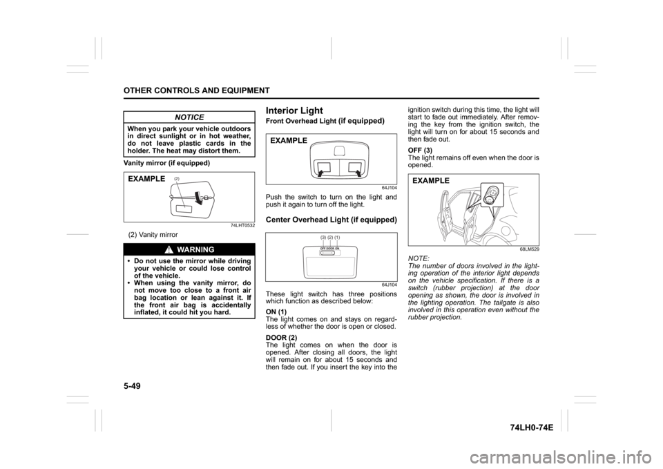
Vanity mirror (if equipped)
74LHT0532
(2) Vanity mirror
Interior Light Front Overhead Light
(if equipped)
64J104
Push the switch to turn on the light and
push it again to turn off the light.Center Overhead Light (if equipped)
64J104
These light switch has three positions
which function as described below:
ON (1)
The light comes on and stays on regard-
less of whether the door is open or closed.
DOOR (2)
The light comes on when the door is
opened. After closing all doors, the light
will remain on for about 15 seconds and
then fade out. If you insert the key into theignition switch during this time, the light will
start to fade out immediately. After remov-
ing the key from the ignition switch, the
light will turn on for about 15 seconds and
then fade out.
OFF (3)
The light remains off even when the door is
opened.
68LM529
NOTE:
The number of doors involved in the light-
ing operation of the interior light depends
on the vehicle specification. If there is a
switch (rubber projection) at the door
opening as shown, the door is involved in
the lighting operation. The tailgate is also
involved in this operation even without the
rubber projection.
NOTICE
When you park your vehicle outdoors
in direct sunlight or in hot weather,
do not leave plastic cards in the
holder. The heat may distort them.
WA R N I N G
Do not use the mirror while driving
your vehicle or could lose control
of the vehicle.
When using the vanity mirror, do
not move too close to a front air
bag location or lean against it. If
the front air bag is accidentally
inflated, it could hit you hard.
(2)
EXAMPLE
EXAMPLE
(1)(2)(3)
EXAMPLE
Page 188 of 336

6-5VEHICLE LOADING AND TOWING
74LH0-74E
A: 2WD VEHICLES WITH MANUAL
TRANSAXLE OR AUTOMATIC
TRANSAXLE OR AUTO GEAR
SHIFT1) Secure the front wheels on a towing
dolly according to the instructions pro-
vided by the dolly manufacturer.
2) Release the parking brake.
NOTICE
The steering column is not strong
enough to withstand shocks trans-
mitted from the front wheels during
towing. Always unlock the steering
wheel before towing. TOWING METHOD AFROM THE FRONT:
FRONT WHEELS ON A DOLLY
AND REAR WHEELS ON THE GROUND
B: 2WD VEHICLES WITH MANUAL TRANSAXLE OR AUTO GEAR SHIFT1) Shift the manual transaxle lever into neutral.
2) Turn the ignition key to the “ACC” position or change the ignition mode to the “ACC” to
unlock the steering wheel.
3) Release the parking brake.
ACC
N
TOWING METHOD BFROM THE FRONT:
FRONT WHEELS ON THE GROUND
Page 192 of 336
7-1INSPECTION AND MAINTENANCE
74LH0-74E
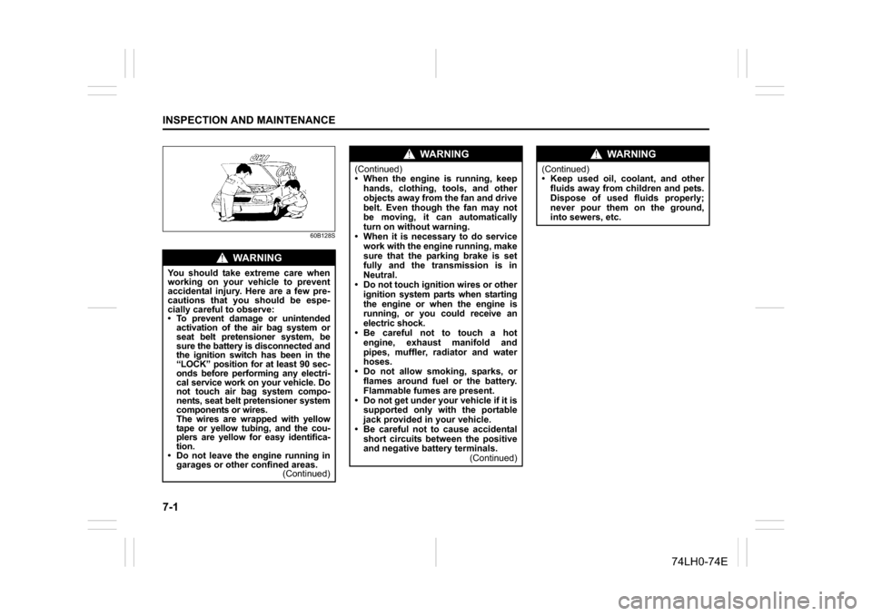
60B128S
WA R N I N G
You should take extreme care when
working on your vehicle to prevent
accidental injury. Here are a few pre-
cautions that you should be espe-
cially careful to observe:
To prevent damage or unintended
activation of the air bag system or
seat belt pretensioner system, be
sure the battery is disconnected and
the ignition switch has been in the
“LOCK” position for at least 90 sec-
onds before performing any electri-
cal service work on your vehicle. Do
not touch air bag system compo-
nents, seat belt pretensioner system
components or wires.
The wires are wrapped with yellow
tape or yellow tubing, and the cou-
plers are yellow for easy identifica-
tion.
Do not leave the engine running in
garages or other confined areas.
(Continued)
WA R N I N G
(Continued)
When the engine is running, keep
hands, clothing, tools, and other
objects away from the fan and drive
belt. Even though the fan may not
be moving, it can automatically
turn on without warning.
When it is necessary to do service
work with the engine running, make
sure that the parking brake is set
fully and the transmission is in
Neutral.
Do not touch ignition wires or other
ignition system parts when starting
the engine or when the engine is
running, or you could receive an
electric shock.
Be careful not to touch a hot
engine, exhaust manifold and
pipes, muffler, radiator and water
hoses.
Do not allow smoking, sparks, or
flames around fuel or the battery.
Flammable fumes are present.
Do not get under your vehicle if it is
supported only with the portable
jack provided in your vehicle.
Be careful not to cause accidental
short circuits between the positive
and negative battery terminals.
(Continued)
WA R N I N G
(Continued)
Keep used oil, coolant, and other
fluids away from children and pets.
Dispose of used fluids properly;
never pour them on the ground,
into sewers, etc.
Page 194 of 336
7-3INSPECTION AND MAINTENANCE
74LH0-74E
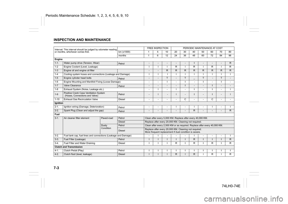
Interval: This interval should be judged by odometer reading
or months, whichever comes first.
FREE INSPECTION
PERIODIC MAINTENANCE AT COST
km (x1000)
1
5
10
20
30
40
50
60
70
80
months
1
6
12
24
36
48
60
72
84
96
Engine
1-1.
Water pump drive (Tension, Wear)
Pe tro l
-
-
-
-
-
I
-
-
-
R
1-2Engine Coolant (Level, Leakage) l l lRlRlRlR
1-3
Engine oil and engine oil filter
-
-
R
R
R
R
R
R
R
R
1-4 Cooling system hoses and connections (Leakage and Damage) l l l l l lllll
1-5
Engine cylinder head bolts
Pe tro l
-
-
T
-
T
_
T
-
T
-
1-6 Engine Mounting and Manifold Fixing (Loose Damage) - - I - I - I - I -
1-7
Valve Clearance
Pe tro l
-
-
-
-
I
-
-
I
-
-
1-8
Exhaust System (Noise, Leakage etc.)
-
l
-
l
-
I
-
I
-
l
1-9
Positive Crank Case Ventilation System (Hoses, Connections and Valve)
Pe tro l
-
l
-
l
-
I
-
I
-
l
1-10 Exhaust Gas Recirculation Valve Diesel - - - - C - - C - -
Ignition2-1.
Ignition wiring (Damage, Deterioration)
Pe tro l
-
-
-
l
-
l
-
l
-
l
2-2.
Spark Plug (Clean and adjust the gap)
Pe tro l
-
-
-
-
-
R
-
-
-
R
Fuel
3-1.
Air cleaner filter element
Paved-road
Pe tro l
Clean after every 5,000 KM. Replace after every 40,000 KM.
Diesel
Replace after every 20,000 KM. Cleaning not required.
Dusty
Condition
Pe tro l
Clean after every 2,500 KM or as required. Replace after every 40,000 KM.
Diesel
Replace after every 20,000 KM. Cleaning not required.
More frequent replacement if dust condition is severe.
3-2.
Fuel tank cap, fuel lines and connections (Leakage and Damage)
-
l
-
-
-
l
-
-
-
l
3-3.
Fuel Filter (Leakage)
Pe tro l
I
I
I
I
I
R
I
I
I
R
3-4.
Fuel Filter and Water Draining
Diesel
I
I
I
R
I
R
I
R
I
R
Clutch and Transmission4-1.
Clutch Pedal (Play)
Pe tro l
I
I
I
I
I
I
I
I
I
I
4-2.
Clutch fluid (level, leakage)
Diesel
l
l
l
R
l
R
l
R
l
R
Periodic Maintenance Schedule: 1, 2, 3, 4, 5, 6, 9, 10
Page 204 of 336
7-13INSPECTION AND MAINTENANCE
74LH0-74E
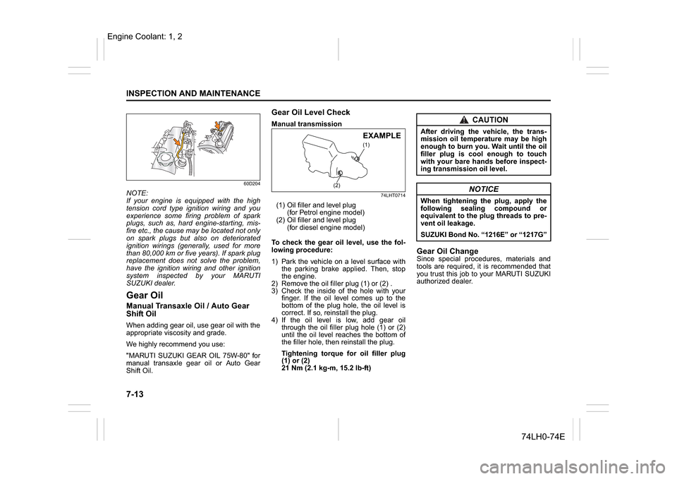
60D204
NOTE:
If your engine is equipped with the high
tension cord type ignition wiring and you
experience some firing problem of spark
plugs, such as, hard engine-starting, mis-
fire etc., the cause may be located not only
on spark plugs but also on deteriorated
ignition wirings (generally, used for more
than 80,000 km or five years). If spark plug
replacement does not solve the problem,
have the ignition wiring and other ignition
system inspected by your MARUTI
SUZUKI dealer.Gear OilManual Transaxle Oil / Auto Gear
Shift OilWhen adding gear oil, use gear oil with the
appropriate viscosity and grade.
We highly recommend you use:
"MARUTI SUZUKI GEAR OIL 75W-80" for
manual transaxle gear oil or Auto Gear
Shift Oil.
Gear Oil Level CheckManual transmission
74LHT0714
(1) Oil filler and level plug
(for Petrol engine model)
(2) Oil filler and level plug
(for diesel engine model)
To check the gear oil level, use the fol-
lowing procedure:
1) Park the vehicle on a level surface with
the parking brake applied. Then, stop
the engine.
2) Remove the oil filler plug (1) or (2) .
3) Check the inside of the hole with your
finger. If the oil level comes up to the
bottom of the plug hole, the oil level is
correct. If so, reinstall the plug.
4) If the oil level is low, add gear oil
through the oil filler plug hole (1) or (2)
until the oil level reaches the bottom of
the filler hole, then reinstall the plug.
Tightening torque for oil filler plug
(1) or (2)
21 Nm (2.1 kg-m, 15.2 lb-ft)
Gear Oil ChangeSince special procedures, materials and
tools are required, it is recommended that
you trust this job to your MARUTI SUZUKI
authorized dealer.
(1)
(2)
EXAMPLE
CAUTION
After driving the vehicle, the trans-
mission oil temperature may be high
enough to burn you. Wait until the oil
filler plug is cool enough to touch
with your bare hands before inspect-
ing transmission oil level.
NOTICE
When tightening the plug, apply the
following sealing compound or
equivalent to the plug threads to pre-
vent oil leakage.
SUZUKI Bond No. “1216E” or “1217G”
Engine Coolant: 1, 2
Page 213 of 336
7-22
INSPECTION AND MAINTENANCE
74LH0-74E
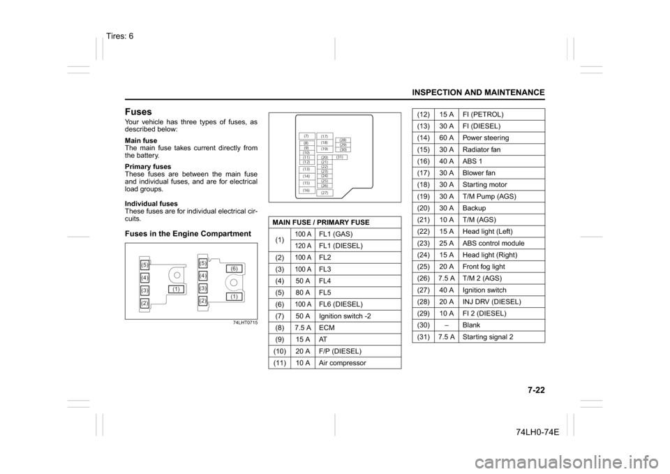
FusesYour vehicle has three types of fuses, as
described below:
Main fuse
The main fuse takes current directly from
the battery.
Primary fuses
These fuses are between the main fuse
and individual fuses, and are for electrical
load groups.
Individual fuses
These fuses are for individual electrical cir-
cuits.Fuses in the Engine Compartment
74LHT0715
(5)
(3) (4)
(2)(1)(5)
(4)
(3)
(2)(1) (6)
MAIN FUSE / PRIMARY FUSE
(1)
100 A
FL1 (GAS)
120 A
FL1 (DIESEL)
(2)
100 A
FL2
(3)
100 A
FL3
(4) 50 A FL4
(5) 80 A FL5
(6)
100 A
FL6 (DIESEL)
(7) 50 A Ignition switch -2
(8) 7.5 A ECM
(9) 15 A AT
(10) 20 A F/P (DIESEL)
(11) 10 A Air compressor
(7)
(8)(9)
(10)
(11)
(12)
(13)
(14)
(15)
(16)(17)
(18)
(20) (19)
(21)
(22)
(23)
(25) (24)
(26)
(27)(28)
(29)
(30)
(31)
(12) 15 A FI (PETROL)
(13) 30 A FI (DIESEL)
(14) 60 A Power steering
(15) 30 A Radiator fan
(16) 40 A ABS 1
(17) 30 A Blower fan
(18) 30 A Starting motor
(19) 30 A T/M Pump (AGS)
(20) 30 A Backup
(21) 10 A T/M (AGS)
(22) 15 A Head light (Left)
(23) 25 A ABS control module
(24) 15 A Head light (Right)
(25) 20 A Front fog light
(26) 7.5 A T/M 2 (AGS)
(27) 40 A Ignition switch
(28) 20 A INJ DRV (DIESEL)
(29) 10 A FI 2 (DIESEL)
(30)
Page 214 of 336
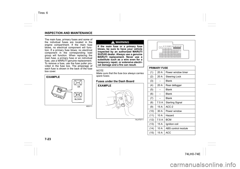
7-23INSPECTION AND MAINTENANCE
74LH0-74E
The main fuse, primary fuses and some of
the individual fuses are located in the
engine compartment. If the main fuse
blows, no electrical component will func-
tion. If a primary fuse blows, no electrical
component in the corresponding load
group will function. When replacing the
main fuse, a primary fuse or an individual
fuse, use a MARUTI genuine replacement.
To remove a fuse, use the fuse puller pro-
vided in the fuse box. The amperage of
each fuse is shown in the back of the fuse
box cover.
60G111
NOTE:
Make sure that the fuse box always carries
spare fuses.Fuses under the Dash Board
74LHT0711
EXAMPLE
BLOWNOK
WA R N I N G
If the main fuse or a primary fuse
blows, be sure to have your vehicle
inspected by an authorized MARUTI
SUZUKI dealer. Always use a genuine
MARUTI replacement. Never use a
substitute such as a wire even for a
temporary repair, or extensive electri-
cal damage and a fire can result.EXAMPLE
PRIMARY FUSE
(1) 20 A Power window timer
(2) 20 A Steering Lock
(3) – Blank
(4) 20 A Rear defogger
(5) – Blank
(6) – Blank
(7) – Blank
(8) 7.5 A Starting Signal
(9) 15 A ACC-2
(10) 30 A Power window
(11) 10 A Hazard
(12) 7.5 A BCM
(13) 15 A Ignition coil
(14) 10 A ABS control module
(15) 15 A ACC
(3)
(12)(10)
(13)
(36) (1) (2) (4)
(5)(6)
(7) (8)(9)
(11) (14) (15)
(16) (17) (18) (19) (20) (21) (22)
(23) (24) (25) (26) (27) (28) (29)
(30) (31) (32) (33) (34) (35)
Tires: 6