Display SUZUKI SX4 2006 1.G Service Workshop Manual
[x] Cancel search | Manufacturer: SUZUKI, Model Year: 2006, Model line: SX4, Model: SUZUKI SX4 2006 1.GPages: 1556, PDF Size: 37.31 MB
Page 1487 of 1556

Downloaded from www.Manualslib.com manuals search engine Body Electrical Control System: 10B-14
DTC CheckS6RW0DA204005
Using SUZUKI Scan Tool
1) Prepare SUZUKI scan tool.
2) With ignition switch turned OFF, connect it to data link connector (DLC) located on underside of instrument panel
of driver’s side.
Special tool
(A): SUZUKI scan tool
3) Turn ignition switch ON.
4) Read DTC according to instructions displayed on SUZUKI scan tool and print it or write it down.
Refer to SUZUKI scan tool operator’s manual for further details.
If communication between SUZUKI scan tool and BCM is not possible, check if SUZUKI scan tool is
communicable by connecting it to BCM in another vehicle. If communication is possible in this case, SUZUKI scan
tool is in good condition. Then check data link connector and serial data line (circuit) in the vehicle with which
communication was not possible.
5) After completing the check, turn ignition switch off and disconnect SUZUKI scan tool from data link connector.
Without Using SUZUKI Scan Tool
1) Turn ignition switch to OFF position.
2) Perform following Steps a) to d) within 10 seconds after ignition switch is turned ON and engine stops.
a) Turn headlight switch to “SMALL” position.
b) Turn headlight switch to “OFF” position.
c) Repeat Steps a) and b) 2 times.
d) Press and release driver side door switch 3 times.
(A)
I5RW0AA20008-02
Page 1488 of 1556

Downloaded from www.Manualslib.com manuals search engine 10B-15 Body Electrical Control System:
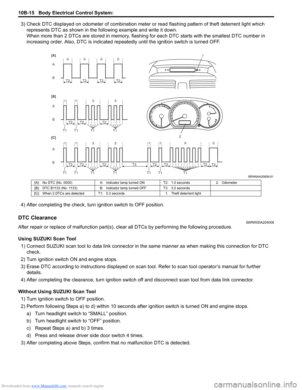
3) Check DTC displayed on odometer of combination meter or read flashing pattern of theft deterrent light which
represents DTC as shown in the following example and write it down.
When more than 2 DTCs are stored in memory, flashing for each DTC starts with the smallest DTC number in
increasing order. Also, DTC is indicated repeatedly until the ignition switch is turned OFF.
4) After completing the check, turn ignition switch to OFF position.
DTC ClearanceS6RW0DA204006
After repair or replace of malfunction part(s), clear all DTCs by performing the following procedure.
Using SUZUKI Scan Tool
1) Connect SUZUKI scan tool to data link connector in the same manner as when making this connection for DTC
check.
2) Turn ignition switch ON and engine stops.
3) Erase DTC according to instructions displayed on scan tool. Refer to scan tool operator’s manual for further
details.
4) After completing the clearance, turn ignition switch off and disconnect scan tool from data link connector.
Without Using SUZUKI Scan Tool
1) Turn ignition switch to OFF position.
2) Perform following Steps a) to d) within 10 seconds after ignition switch is turned ON and engine stops.
a) Turn headlight switch to “SMALL” position.
b) Turn headlight switch to “OFF” position.
c) Repeat Steps a) and b) 3 times.
d) Press and release driver side door switch 4 times.
3) After completing above Steps, confirm that no malfunction DTC is detected.
B A [B] [A]
[C]
B A B A
3 113
3 113 T2
T1 T1 T1T1
1
2
T2T2
T2
T1 T1 T1T1T2T2
0
T2
0
T2
0
T2
0
T2
11 6 0
T1 T1 T1
T2 T3T2T2T2
I5RW0AA20009-01
[A]: No DTC (No. 0000) A: Indicator lamp turned ON T2: 1.0 seconds 2. Odometer
[B]: DTC B1133 (No. 1133) B: Indicator lamp turned OFF T3: 3.0 seconds
[C]: When 2 DTCs are detected T1: 0.3 seconds 1. Theft deterrent light
Page 1496 of 1556

Downloaded from www.Manualslib.com manuals search engine 10B-23 Body Electrical Control System:
BCM connector “G04”E04-13 — — —
E04-14 — — —
Terminal Circuit Normal voltage Condition
G04-1CAN communication line (low)
for DLC*1.6 – 2.5 V
Refer to “Reference waveform No. 3: ” G04-2CAN communication line (low)
for each control module*1.6 – 2.5 V
G04-3CAN communication line
(high) for DLC*2.5 – 3.6 V
G04-4CAN communication line
(high) for each control module*2.5 – 3.6 V
G04-5Serial communication line of
data link connector 7 – 12 V Ignition switch is at ON position
G04-6 — — —
G04-7 — — —
G04-8 Theft deterrent light10 – 14 V Theft deterrent light is not lit up
0 V Theft deterrent light is lit up
G04-9 — — —
G04-10 — — —
G04-11Serial communication line for
information display and HVAC
control module (if equipped)*0 – 1 V
↑↓
10 – 14 VRefer to “Reference waveform No. 5: ”
G04-12Ground for keyless entry
receiver (if equipped)0 V —
G04-13Power supply for keyless
entry receiver (if equipped)4 – 6 V Ignition switch is at all positions
G04-14Signal for keyless entry
receiver (if equipped)*0 – 1 V
↑↓
4 – 6 VRefer to “Reference waveform No. 6: ”
G04-15 Vehicle speed signal output*0 – 1 V
↑↓
4 – 6VRefer to “Reference waveform No. 7: ”
G04-16 Key reminder switch10 – 14 V Ignition key is inserted to ignition key cylinder
0 VIgnition key is pulled out from ignition key
cylinder
G04-17Rear end door window
defogger switch*3 – 14 V Refer to “Reference waveform No. 8: ”
0 VIgnition switch is at ON position and rear end
door window defogger switch is pushed
G04-18 A/C switch (if equipped)*3 – 14 V Refer to “Reference waveform No. 8: ”
0 VIgnition switch is at ON position, blower speed
selector is at any position other than OFF
position and A/C switch is at ON position
G04-19 — — —
G04-20 — — —
G04-21 Rear wiper INT switch*0 – 1 V
↑↓
10 – 14 VRefer to “Reference waveform No. 9: ”
0 VIgnition switch is at ON position and rear
wiper switch is at INT position
G04-22 Rear wiper low switch*0 – 1 V
↑↓
10 – 14 VRefer to “Reference waveform No. 9: ”
0 VIgnition switch is at ON position and rear
wiper switch is at LOW position Terminal Circuit Normal voltage Condition
Page 1500 of 1556

Downloaded from www.Manualslib.com manuals search engine 10B-27 Body Electrical Control System:
Reference waveform No. 5
Information display and HVAC control module serial
communication signal (1)
Reference waveform No. 6
Keyless entry receiver signal (1)Reference waveform No. 7
Vehicle speed pulse output signal (1)
Reference waveform No. 8
A/C or rear end door window defogger switch signal (1) Measurement terminal CH2: “G04-11” to “G271-3”
Oscilloscope setting CH2: 5 V / DIV
TIME: 2 ms / DIV
Measurement
conditionIgnition switch is at ON position
Measurement terminal CH2: “G04-14” to “G271-3”
Oscilloscope setting CH2: 2 V / DIV
TIME: 200 ms / DIV
Measurement
conditionLock or unlock button of
keyless entry transmitter is
pushed
I4RS0AA20021-02
I4RS0AA20022-02
Measurement terminal CH1: “G04-15” to “G271-3”
Oscilloscope setting CH1: 2 V / DIV
TIME: 100 ms / DIV
Measurement
conditionVehicle speed at 10 km/h (6
mph)
Measurement terminal Rear end door window
defogger switch
CH2: “G04-17” to “G271-3”
A/C switch
CH2: “G04-18” to “G271-3”
Oscilloscope setting CH2: 5 V/DIV
TIME: 10 ms/DIV
Measurement
conditionRear end door window
defogger switch:
• Ignition switch is at ON
position and rear end door
window defogger switch is
not pushed
A/C switch:
• Ignition switch is at ON
position, A/C switch or
blower speed selector is at
OFF position
I5RW0AA20014-01
I4RS0AA20023-02
Page 1508 of 1556

Downloaded from www.Manualslib.com manuals search engine 10C-6 Immobilizer Control System:
DTC CheckS6RW0DA304002
NOTE
To know how to use SUZUKI scan tool in
detail, refer to its operator’s manual.
1) Turn the ignition switch to OFF position.
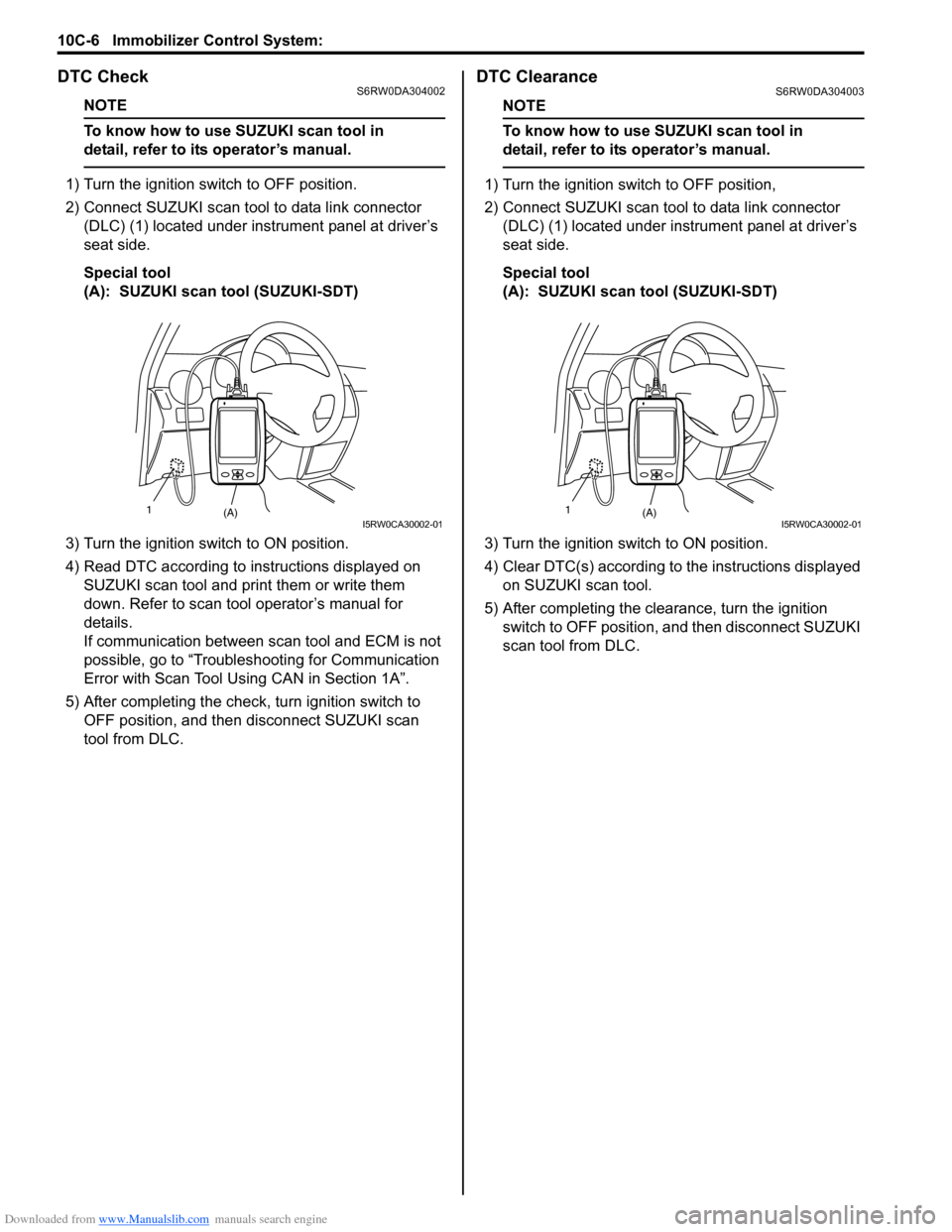
2) Connect SUZUKI scan tool to data link connector
(DLC) (1) located under instrument panel at driver’s
seat side.
Special tool
(A): SUZUKI scan tool (SUZUKI-SDT)
3) Turn the ignition switch to ON position.
4) Read DTC according to instructions displayed on
SUZUKI scan tool and print them or write them
down. Refer to scan tool operator’s manual for
details.
If communication between scan tool and ECM is not
possible, go to “Troubleshooting for Communication
Error with Scan Tool Using CAN in Section 1A”.
5) After completing the check, turn ignition switch to
OFF position, and then disconnect SUZUKI scan
tool from DLC.
DTC ClearanceS6RW0DA304003
NOTE
To know how to use SUZUKI scan tool in
detail, refer to its operator’s manual.
1) Turn the ignition switch to OFF position,
2) Connect SUZUKI scan tool to data link connector
(DLC) (1) located under instrument panel at driver’s
seat side.
Special tool
(A): SUZUKI scan tool (SUZUKI-SDT)
3) Turn the ignition switch to ON position.
4) Clear DTC(s) according to the instructions displayed
on SUZUKI scan tool.
5) After completing the clearance, turn the ignition
switch to OFF position, and then disconnect SUZUKI
scan tool from DLC.
(A) 1I5RW0CA30002-01(A) 1I5RW0CA30002-01
Page 1510 of 1556

Downloaded from www.Manualslib.com manuals search engine 10C-8 Immobilizer Control System:
Scan Tool DataS6RW0DA304005
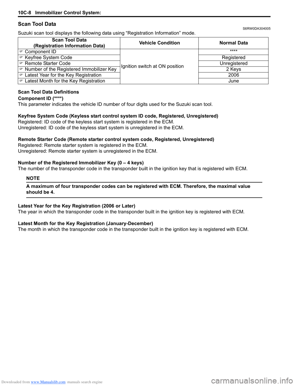
Suzuki scan tool displays the following data using “Registration Information” mode.
Scan Tool Data Definitions
Component ID (****)
This parameter indicates the vehicle ID number of four digits used for the Suzuki scan tool.
Keyfree System Code (Keyless start control system ID code, Registered, Unregistered)
Registered: ID code of the keyless start system is registered in the ECM.
Unregistered: ID code of the keyless start system is unregistered in the ECM.
Remote Starter Code (Remote starter control system code, Registered, Unregistered)
Registered: Remote starter system is registered in the ECM.
Unregistered: Remote starter system is unregistered in the ECM.
Number of the Registered Immobilizer Key (0 – 4 keys)
The number of the transponder code in the transponder built in the ignition key that is registered with ECM.
NOTE
A maximum of four transponder codes can be registered with ECM. Therefore, the maximal value
should be 4.
Latest Year for the Key Registration (2006 or Later)
The year in which the transponder code in the transponder built in the ignition key is registered with ECM.
Latest Month for the Key Registration (January-December)
The month in which the transponder code in the transponder built in the ignition key is registered with ECM. Scan Tool Data
(Registration Information Data)Vehicle Condition Normal Data
�) Component ID
Ignition switch at ON position****
�) Keyfree System Code Registered
�) Remote Starter Code Unregistered
�) Number of the Registered Immobilizer Key 2 Keys
�) Latest Year for the Key Registration 2006
�) Latest Month for the Key Registration June