check engine light SUZUKI SX4 2006 1.G Service Workshop Manual
[x] Cancel search | Manufacturer: SUZUKI, Model Year: 2006, Model line: SX4, Model: SUZUKI SX4 2006 1.GPages: 1556, PDF Size: 37.31 MB
Page 1062 of 1556
Downloaded from www.Manualslib.com manuals search engine 8B-23 Air Bag System:
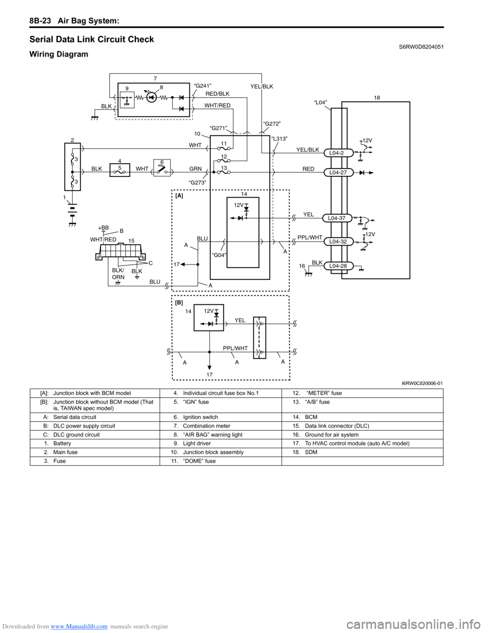
Serial Data Link Circuit CheckS6RW0D8204051
Wiring Diagram
1
2
3
3
18
12V
RED 7
14 9
10
“L313”
“G273”
YEL/BLKL04-2
L04-27 “L04”
PPL/WHT
“G04”L04-3212V
8
GRN
15
+BB
56WHTWHT
4
BLUBLU
BLK
16
11
12
“G241”
13
BLK
L04-28
RED/BLK
WHT/REDYEL/BLK
BLK“G271”
“G272”
WHT/RED
BLK/
ORNBLK
B
C
A A
A
17
[A]
A
[B]
12V
PPL/WHTYEL14
17A
A
YELL04-37
12V
I6RW0C820006-01
[A]: Junction block with BCM model 4. Individual circuit fuse box No.1 12. “METER” fuse
[B]: Junction block without BCM model (That
is, TAIWAN spec model)5. “IGN” fuse 13. “A/B” fuse
A: Serial data circuit 6. Ignition switch 14. BCM
B: DLC power supply circuit 7. Combination meter 15. Data link connector (DLC)
C: DLC ground circuit 8. “AIR BAG” warning light 16. Ground for air system
1. Battery 9. Light driver 17. To HVAC control module (auto A/C model)
2. Main fuse 10. Junction block assembly 18. SDM
3. Fuse 11. “DOME” fuse
Page 1063 of 1556

Downloaded from www.Manualslib.com manuals search engine Air Bag System: 8B-24
Troubleshooting
Step Action Yes No
1“AIR BAG” warning light check
1) Turn ignition switch to ON position.
Does “AIR BAG” warning light come ON steady?Go to ““AIR BAG”
Warning Light Comes
ON Steady”.Go to Step 2.
2Scan tool condition check
1) Make sure that SUZUKI scan tool is as follows.
• Correct PCMCIA card (software) is used.
• There are no deformation and wear for DLC cable
terminals.
• Connection for DLC cable terminals is in good
condition.
Are they OK?Go to Step 3. Repair or replace
defective part.
3Scan tool operation check
1) Check DLC terminal for deformation and wear.
2) If it is in good condition, connect SUZUKI scan tool to
DLC with ignition switch turned OFF.
3) Check if communication is possible by making
communication with other control modules (BCM, ABS
control module, HVAC control module (auto A/C model)
or P/S control module).
Is it possible to communicate with the other control
modules?Go to Step 4. Go to Step 6.
4Serial communication circuit check
1) With ignition switch turned OFF, disconnect SDM
connector “L04” and check for proper connection at
SDM connector terminal.
2) If connections are OK, check that “Serial data circuit” is
as follows.
• Wiring resistance of “Serial data circuit” wire between
DLC and SDM connector is less than 1 Ω.
Is it resistance less than 1
Ω?Go to Step 5. “Serial data circuit” is
open or high resistance.
5SDM power and ground circuit check
1) Check power supply circuit and ground circuit for SDM
referring to “SDM Power Supply and Ground Circuit
Check”.
Is check result in good condition?Substitute a known-
good SDM and recheck.Repair or replace
defective circuit.
6DLC power and ground circuit check
1) Check power supply circuit and ground circuit for DLC as
follows.
• Voltage of “DLC power supply circuit” between DLC
terminal and vehicle body ground is 10 – 14 V with
ignition switch turned ON.
• Wire resistance of each “DLC ground circuit” between
DLC terminal and vehicle body ground is less than
1Ω.
Is check result in good condition?Go to Step 7. Repair or replace
defective circuit.
Page 1065 of 1556
Downloaded from www.Manualslib.com manuals search engine Air Bag System: 8B-26
DTC B1014: “AIR BAG” Warning Light CircuitS6RW0D8204011
Wiring Diagram
Refer to““AIR BAG” Warning Light Comes ON Steady”.
DTC Detecting Condition and Trouble Area
DTC Troubleshooting
NOTE
Upon completion of inspection and repair work, perform the following items.
• Reconnect all air bag system components and ensure all components are properly mounted.
• Clear DTCs referring to “DTC Clearance”, if any.
• Repeat “Air Bag Diagnostic System Check” to confirm that the trouble has been corrected.
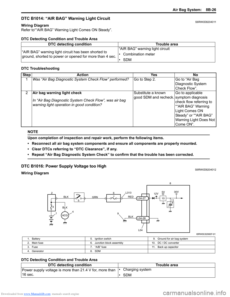
DTC B1016: Power Supply Voltage too HighS6RW0D8204012
Wiring Diagram
DTC Detecting Condition and Trouble AreaDTC detecting condition Trouble area
“AIR BAG” warning light circuit has been shorted to
ground, shorted to power or opened for more than 4 sec.“AIR BAG” warning light circuit
• Combination meter
•SDM
Step Action Yes No
1Was “Air Bag Diagnostic System Check Flow” performed?Go to Step 2. Go to “Air Bag
Diagnostic System
Check Flow”.
2Air bag warning light check
In “Air Bag Diagnostic System Check Flow”, was air bag
warning light operation in good condition?Substitute a known
good SDM and recheck.Go to applicable
symptom diagnosis
check flow referring to
““AIR BAG” Warning
Light Comes ON
Steady” or ““AIR BAG”
Warning Light Does Not
Come ON”.
BLK
L04
7
RED
GRN L313
98
L04-28
L04-27
1
2
3
BLK
45 BLK6
ACG
10
12V5V30V
11
I6RW0C820007-01
1. Battery 5. Ignition switch 9. Ground for air bag system
2. Main fuse 6. Junction block assembly 10. DC / DC converter
3. Fuse 7. “A/B” fuse 11. Back up capacitor
4. Generator 8. SDM
DTC detecting condition Trouble area
Power supply voltage is more than 21.4 V for, more than
16 sec.• Charging system
•SDM
Page 1124 of 1556
Downloaded from www.Manualslib.com manuals search engine 8B-85 Air Bag System:
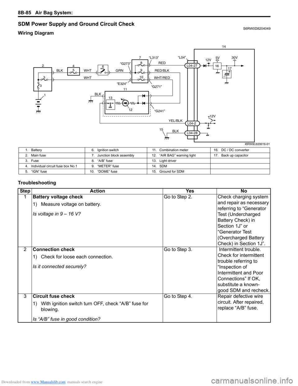
SDM Power Supply and Ground Circuit CheckS6RW0D8204049
Wiring Diagram
Troubleshooting
“L04”14
5
9RED
RED/BLK GRN
YEL/BLK
BLK
8 7
11
12
15
L04-2
L04-28
L04-27
“G241” “G271” “L313”
13
12V
6
1BLK
WHT WHT
WHT/RED 2
34
310 BLK
“G273”
“E324”16
12V5V30V
17
I6RW0C820016-01
1. Battery 6. Ignition switch 11. Combination meter 16. DC / DC converter
2. Main fuse 7. Junction block assembly 12. “AIR BAG” warning light 17. Back up capacitor
3. Fuse 8. “A/B” fuse 13. Light driver
4. Individual circuit fuse box No.1 9. “METER” fuse 14. SDM
5. “IGN” fuse 10. “DOME” fuse 15. Ground for SDM
Step Action Yes No
1Battery voltage check
1) Measure voltage on battery.
Is voltage in 9 – 16 V?Go to Step 2. Check charging system
and repair as necessary
referring to “Generator
Test (Undercharged
Battery Check) in
Section 1J” or
“Generator Test
(Overcharged Battery
Check) in Section 1J”.
2Connection check
1) Check for loose each connection.
Is it connected securely?Go to Step 3. Intermittent trouble.
Check for intermittent
trouble referring to
“Inspection of
Intermittent and Poor
Connections” If OK,
substitute a known-
good SDM and recheck.
3Circuit fuse check
1) With ignition switch turn OFF, check “A/B” fuse for
blowing.
Is “A/B” fuse in good condition?Go to Step 4. Repair defective wire
circuit. After repaired,
replace “A/B” fuse.
Page 1129 of 1556

Downloaded from www.Manualslib.com manuals search engine Air Bag System: 8B-90
• Improperly formed or damaged terminals.
Check each connector terminal in problem circuits
carefully to ensure good contact tension by using the
corresponding mating terminal included in the
connector test adapter kit (special tool).
If contact tension is not enough, reform the terminal to
increase contact tension or replace it.
Special tool
(A): 09932–76010 Connector test adapter kit
• Poor terminal-to-wire connection.
Check each wire harness in problem circuits for poor
connection by shaking it by hand lightly. If any
abnormal condition is found, change the wire harness
assembly or component parts with new ones.
• Wire insulation which is rubbed through, causing an
intermittent short as the bare area touches other
wiring or parts of the vehicle.
• Wire broken inside the insulation. This condition could
cause a continuity check to show a good circuit, but if
only 1 or 2 strands of a multi-strand-type wire are
intact, resistance could be far too high.
Repair and Inspection Required after AccidentS6RW0D8204048
CAUTION!
• All air bag system components, including
the electrical harness (component
mounting points), must be inspected after
an accident. If any components are
damaged or bent, they must be replaced
even if air bag system activation did not
occur.
• Never use air bag system parts from
another vehicle.
• Do not attempt to service the parts below.
Service of these parts is by replacement
only.
– Driver / Passenger air bag (inflator)
modules
– Driver / Passenger side-air bag (inflator)
modules
– Driver / Passenger side curtain-air bag
(inflator) modules
– Driver / Passenger seat belt
pretensioners
– Forward impact-sensor
– Driver / Passenger side impact-sensors
–SDM
– Contact coil and combination switch
assembly
– Air bag wire harness in main harness,
instrument panel harness, floor harness,
passenger air bag harness, side-air bag
harness and side curtain-air bag
harness.
• Proper operation of the sensors and air
bag system requires that any repairs to the
vehicle structure return it to its original
production configuration.
(A)
I4RS0A820045-01
IYSQ01010028-01
IYSQ01820025-01
Page 1131 of 1556

Downloaded from www.Manualslib.com manuals search engine Air Bag System: 8B-92
– Check connector or lead wire of SDM for scorching,
melting or damage.
– Check SDM connector and terminals for tightness.
– Check if SDM sets a DTC and is judged as
malfunctioning according to the diagnostic flow.
• Air bag wire harness and connections
– Check for damages, deformities or poor
connections.
Refer to “Inspection of Intermittent and Poor
Connections”.
– Check wire harness clamps for tightness.
• Forward impact-sensor
– Check sensor (1) and apron-side-member (driver
side) (2) for damage, bend or rust.
– Check connector (3) or lead wire (4) of forward-
sensor for scorching, melting or damage.• Side impact-sensor
– Check sensor (1) and under body (2) for dents,
cracks, deformation or rust.
– Check sensor connector (sensor side and harness
side) (3) or sensor lead wire (4) for damage, crack,
scorching or melting.
• Seat belt pretensioner
– Check for dents, cracks, damage or fitness
– Check harness and connector for damage or
tightness.
• Seat belts and mounting points
– Refer to “Front Seat Belt Components in Section
8A”.
• “AIR BAG” warning light
– After vehicle is completely repaired, perform “Air
Bag Diagnostic System Check”.
• Side-air bag (inflator) module
– Check for dents, cracks, damage or fitness.
– Check trim cover for cracks or deformities.
– Check wire harness and connector for damage or
tightness.
• Side curtain-air bag (inflator) module
– Check for dents, cracks, damage or fitness.
– Check harness wire harness and connector for
damage or tightness.
– Check headlining for cracks or deformation.
1. Main harness 5. Side-air bag harness
2. Grounding point 6. Side curtain-air bag harness
3. Floor harness 7. Side curtain-air bag (inflator)
module
4. Instrument panel harness
I5RH01820092-01
4
1
26
3
5
7
I6RW0C820018-01
1
23
4I5RW0A820059-01
1. Seat belt 2. Retractor assembly
3 2
1
4
I5RW0A820060-01
I3JA01820043-01
Page 1133 of 1556

Downloaded from www.Manualslib.com manuals search engine Air Bag System: 8B-94
5) Install driver and passenger side front pillar lower
trim.
6) Side-air bag (inflator) model:
Connect yellow connector (1) of side-air bag
(inflator) module by pushing connector till click is
heard from it.
7) Side curtain-air bag (inflator) model:
Connect yellow connector (1) of side curtain-air bag
(inflator) module by pushing connector till click is
heard from it.
8) Install right-side rear quarter lower trim.
9) Install “A/B” fuse to fuse box.
10) Connect negative (–) cable at battery.
11) Turn ignition switch to ON position and verify that
“AIR BAG” warning light flashes 6 times and then
turns OFF. If it does not operate as described,
perform “Air Bag Diagnostic System Check”.
SDM Removal and InstallationS6RW0D8206003
WARNING!
During service procedures, be very careful
when handling a Sensing and Diagnostic
Module (SDM).
Be sure to read “Precautions on Service and
Diagnosis of Air Bag System” before starting
to work and observe every precaution during
work. Neglecting them may result in personal
injury or inactivation of the air bag system
when necessary.
Removal
1) Disconnect negative (–) cable at battery.
2) Disable air bag system referring to “Disabling Air
Bag System”.
3) Remove console box referring to “Console Box
Components in Section 9H”.
4) Remove G sensor referring to “G Sensor Removal
and Installation (4WD Model) in Section 4E” and its
bracket (1).
5) Disconnect SDM connector (1) from SDM (2).
6) Remove SDM (2) from vehicle.
1
I5JB0A820070-01
1
I5RW0A820063-01
2. SDM
A: Forward
1
2
I5RW0A820064-01
2
1
A
I4RS0A820056-01
Page 1162 of 1556
Downloaded from www.Manualslib.com manuals search engine 9-ii Table of Contents
B-9 Keyless Start System Circuit Diagram...... 9A-103
C-1 Combination Meter Circuit Diagram
(Meter) .......................................................... 9A-104
C-2 Combination Meter Circuit Diagram
(Indicator) ...................................................... 9A-105
C-3 Combination Meter Circuit Diagram
(Warning Light) ............................................. 9A-106
D-1 Headlight System Circuit Diagram
(Except Taiwan) ............................................ 9A-108
D-1 Headlight System Circuit Diagram
(Taiwan) ........................................................ 9A-110
D-2 Position, Tail and Licence Plate Light
System Circuit Diagram (Except Taiwan) ..... 9A-111
D-2 Position, Tail and Licence Plate Light
System Circuit Diagram (Taiwan) ................. 9A-112
D-3 Front Fog Light System Circuit Diagram
(Except Taiwan) ............................................ 9A-113
D-3 Front Fog Light System Circuit Diagram
(Taiwan) ........................................................ 9A-114
D-4 Illumination Light System Circuit Diagram
(Except Taiwan) ............................................ 9A-115
D-4 Illumination Light System Circuit Diagram
(Taiwan) ........................................................ 9A-116
D-5 Interior Light System Circuit Diagram
(Except Taiwan) ............................................ 9A-117
D-5 Interior Light System Circuit Diagram
(Taiwan) ........................................................ 9A-118
D-6 Turn Signal and Hazard Warning Light
System Circuit Diagram (Except Taiwan) ..... 9A-119
D-6 Turn Signal and Hazard Warning Light
System Circuit Diagram (Taiwan) ................. 9A-121
D-7 Brake Light System Circuit Diagram ........ 9A-123
D-8 Back-Up Light System Circuit Diagram .... 9A-124
D-9 Headlight Beam Leveling System Circuit
Diagram (Manual Leveling)........................... 9A-125
D-10 Rear Fog Light Circuit Diagram .............. 9A-126
E-1 Heater System Circuit Diagram ................ 9A-127
E-2 Auto A/C System Circuit Diagram ............ 9A-129
F-1 Air-Bag System Circuit Diagram (4ch) ...... 9A-131
F-1 Air-Bag System Circuit Diagram (8ch) ...... 9A-132
F-2 Anti-Lock Brake System Circuit Diagram.. 9A-134
F-4 Power Steering System Circuit Diagram .. 9A-136
G-1 Audio System Circuit Diagram ................. 9A-138
G-2 Multi Information Display / Accessory
Socket System Circuit Diagram .................... 9A-140
G-4 Navigation System Circuit Diagram ......... 9A-141
List of Connector .............................................9A-143
List of Connectors ........................................... 9A-143
C Connector .................................................... 9A-143
E Connector .................................................... 9A-145
G Connector .................................................... 9A-146
J Connector ..................................................... 9A-149
K Connector .................................................... 9A-149
L Connector..................................................... 9A-150
O Connector .................................................... 9A-152
Q Connector (8ch)........................................... 9A-152
R Connector .................................................... 9A-152
S Connector .................................................... 9A-152
Lighting Systems .................................... 9B-1
Precautions ...........................................................9B-1
Precautions for Discharge Headlight Service
(If Equipped)...................................................... 9B-1
Precautions in Diagnosing Troubles
(Headlight Auto Leveling System) ..................... 9B-1
General Description .............................................9B-1
Discharge Headlight Description (If
Equipped) .......................................................... 9B-1
Headlight Auto Leveling System Description
(If Equipped)...................................................... 9B-2
Auto-On Headlight System Description (If
Equipped) .......................................................... 9B-4
Schematic and Routing Diagram ........................9B-5
Headlight Auto Leveling System Wiring
Circuit Diagram ................................................. 9B-5
Component Location ...........................................9B-6
Lighting System Components Location............... 9B-6
Interior Light System Location............................. 9B-7
Diagnostic Information and Procedures ............9B-7
Self-Diagnosis Function for Headlight Auto
Leveling System ................................................ 9B-7
Headlight Leveling Warning Light Check ............ 9B-8
Headlight Symptom Diagnosis (Discharge
Headlight Model) ............................................... 9B-8
Headlight Symptom diagnosis (Other than
Discharge Headlight Model) .............................. 9B-9
Auto-On Headlight System Symptom
Diagnosis (If Equipped) ..................................... 9B-9
DRL System Symptom Diagnosis (If
Equipped) ........................................................ 9B-10
Headlight Auto Leveling System Symptom
Diagnosis (If Equipped) ................................... 9B-10
Headlight Manual Leveling System Symptom
Diagnosis (If Equipped) ................................... 9B-10
Turn Signal and Hazard Warning Light
Symptom Diagnosis ........................................ 9B-11
Clearance, Tail and License Plate Light
Symptom Diagnosis ........................................ 9B-11
Back-Up Light Symptom Diagnosis................... 9B-12
Brake Light Symptom Diagnosis ....................... 9B-12
Front Fog Light Symptom Diagnosis (If
Equipped) ........................................................ 9B-12
Rear Fog Light Symptom Diagnosis (If
Equipped) ........................................................ 9B-12
Illumination Cancel System Symptom
Diagnosis (If Equipped) ................................... 9B-13
Interior Light Symptom Diagnosis ..................... 9B-13
DRL Operation Inspection (If Equipped) ........... 9B-13
Inspection of DRL Controller and Its Circuits
(If Equipped).................................................... 9B-13
Auto-On Headlight Operation Inspection (If
Equipped) ........................................................ 9B-15
Inspection of Auto-On Headlight Controller
and Its Circuit (If Equipped)............................. 9B-15
Inspection of Headlight Leveling Control
Module and Its Circuit (Headlight Auto
Leveling System)............................................. 9B-16
Repair Instructions ............................................9B-18
Headlight Housing Removal and Installation .... 9B-18
Page 1168 of 1556
Downloaded from www.Manualslib.com manuals search engine 9A-1 Wiring Systems:
Body, Cab and Accessories
Wiring Systems
Precautions
Cautions in Body Electrical System ServicingS6RW0D9100001
When servicing the electric systems, observe the cautions described in “Air Bag Warning in Section 00” to protect
electrical parts and to prevent a fire.
General Description
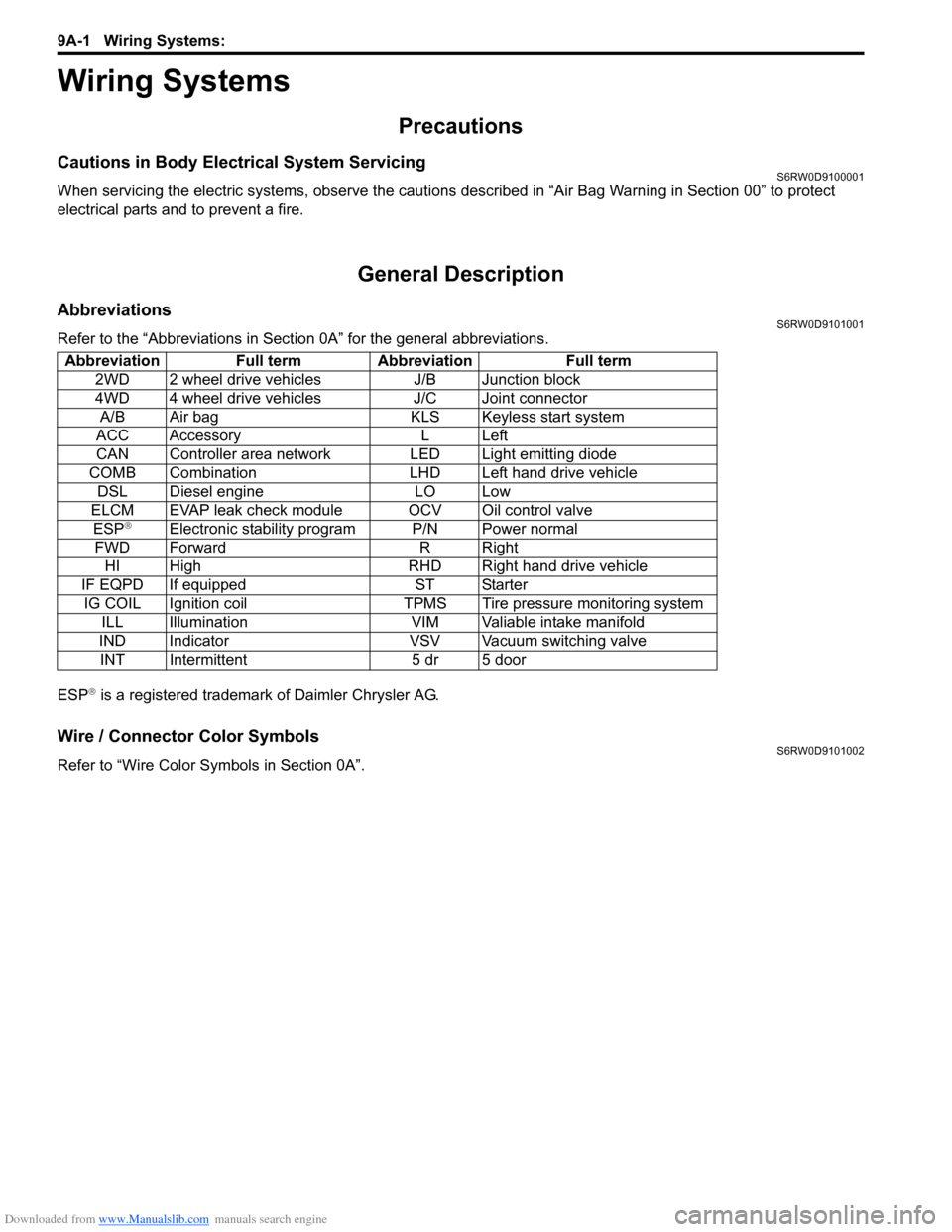
AbbreviationsS6RW0D9101001
Refer to the “Abbreviations in Section 0A” for the general abbreviations.
ESP
® is a registered trademark of Daimler Chrysler AG.
Wire / Connector Color SymbolsS6RW0D9101002
Refer to “Wire Color Symbols in Section 0A”. Abbreviation Full term Abbreviation Full term
2WD 2 wheel drive vehicles J/B Junction block
4WD 4 wheel drive vehicles J/C Joint connector
A/B Air bag KLS Keyless start system
ACC Accessory L Left
CAN Controller area network LED Light emitting diode
COMB Combination LHD Left hand drive vehicle
DSL Diesel engine LO Low
ELCM EVAP leak check module OCV Oil control valve
ESP
®Electronic stability program P/N Power normal
FWD Forward R Right
HI High RHD Right hand drive vehicle
IF EQPD If equipped ST Starter
IG COIL Ignition coil TPMS Tire pressure monitoring system
ILL Illumination VIM Valiable intake manifold
IND Indicator VSV Vacuum switching valve
INT Intermittent 5 dr 5 door
Page 1327 of 1556
Downloaded from www.Manualslib.com manuals search engine Lighting Systems: 9B-8
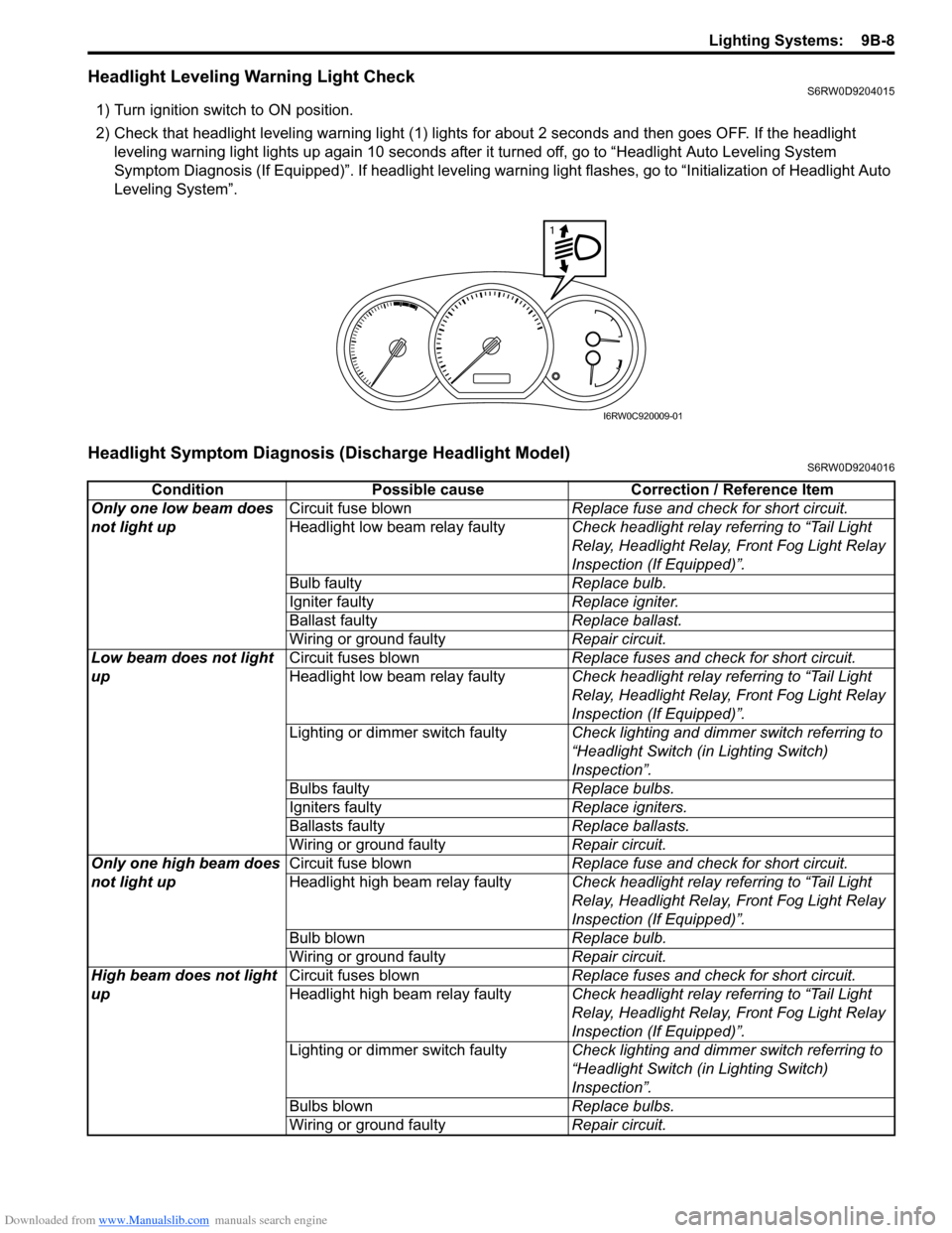
Headlight Leveling Warning Light CheckS6RW0D9204015
1) Turn ignition switch to ON position.
2) Check that headlight leveling warning light (1) lights for about 2 seconds and then goes OFF. If the headlight
leveling warning light lights up again 10 seconds after it turned off, go to “Headlight Auto Leveling System
Symptom Diagnosis (If Equipped)”. If headlight leveling warning light flashes, go to “Initialization of Headlight Auto
Leveling System”.
Headlight Symptom Diagnosis (Discharge Headlight Model)S6RW0D9204016
1
I6RW0C920009-01
Condition Possible cause Correction / Reference Item
Only one low beam does
not light upCircuit fuse blownReplace fuse and check for short circuit.
Headlight low beam relay faultyCheck headlight relay referring to “Tail Light
Relay, Headlight Relay, Front Fog Light Relay
Inspection (If Equipped)”.
Bulb faultyReplace bulb.
Igniter faultyReplace igniter.
Ballast faultyReplace ballast.
Wiring or ground faultyRepair circuit.
Low beam does not light
upCircuit fuses blownReplace fuses and check for short circuit.
Headlight low beam relay faultyCheck headlight relay referring to “Tail Light
Relay, Headlight Relay, Front Fog Light Relay
Inspection (If Equipped)”.
Lighting or dimmer switch faultyCheck lighting and dimmer switch referring to
“Headlight Switch (in Lighting Switch)
Inspection”.
Bulbs faultyReplace bulbs.
Igniters faultyReplace igniters.
Ballasts faultyReplace ballasts.
Wiring or ground faultyRepair circuit.
Only one high beam does
not light upCircuit fuse blownReplace fuse and check for short circuit.
Headlight high beam relay faultyCheck headlight relay referring to “Tail Light
Relay, Headlight Relay, Front Fog Light Relay
Inspection (If Equipped)”.
Bulb blownReplace bulb.
Wiring or ground faultyRepair circuit.
High beam does not light
upCircuit fuses blownReplace fuses and check for short circuit.
Headlight high beam relay faultyCheck headlight relay referring to “Tail Light
Relay, Headlight Relay, Front Fog Light Relay
Inspection (If Equipped)”.
Lighting or dimmer switch faultyCheck lighting and dimmer switch referring to
“Headlight Switch (in Lighting Switch)
Inspection”.
Bulbs blownReplace bulbs.
Wiring or ground faultyRepair circuit.