AUTOMATIC TRANS SUZUKI SX4 2006 1.G Service Workshop Manual
[x] Cancel search | Manufacturer: SUZUKI, Model Year: 2006, Model line: SX4, Model: SUZUKI SX4 2006 1.GPages: 1556, PDF Size: 37.31 MB
Page 997 of 1556

Downloaded from www.Manualslib.com manuals search engine Air Conditioning System: Automatic Type 7B-57
SUN LOAD (W/m2): This parameter indicates the
amount of sunlight detected by sunload sensor.
MODE CONT SWITCH (Air flow selector position,
AUTO, FACE, B/L, FOOT, D/F, DEF): This
parameter indicates the selected position of air flow
selector.
FAN CONT SWITCH (Blower speed selector, AUTO,
OFF, 1st – 8th): This parameter indicates the
selected position of blower speed selector.
FAN DESIRE VOLT (Fan desired voltage, V): This
parameter indicates the consumption voltage of
blower motor.
AIR MIX POS SENSOR (Temperature control
actuator position sensor, V): This parameter
indicates the input signal from position sensor in
temperature control actuator.
MODE POS SENSOR (Air flow control actuator
position sensor, V): This parameter indicates the
input signal from position sensor in air flow control
actuator.
A/C CONT SIG (A/C control signal, ON, OFF): This
parameter indicates the state of A/C switch.BLOWER LOAD SIG (Blower fan load signal, ON,
OFF): ON: Position of blower speed selector is 1st
position or more.
OFF: Position of blower speed selector is OFF
position.
AIR INTAKE MODE (Air intake selector position,
AUTO, FRE, REC): This parameter indicates the
selected position of air intake selector.
REFRIGERANT PRESSURE (A/C refrigerant absolute
pressure, kPa): This parameter indicates the A/C
refrigerant absolute pressure calculated by ECM
A/C COMP CLUCH (A/C compressor magnet clutch,
ON, OFF): This parameter indicates the state of the
A/C compressor magnet clutch.
VEHICLE SPEED (km/h, mph): This parameter
indicates the vehicle speed calculated by ECM.
ENGINE TYPE (Engine type signal, J20, M16 or
M15): This parameter indicates the engine type
signal transmitted by ECM.
METER SPEC (Combination meter spec signal, EU,
UK, US, Canada, DOM): This parameter indicates
the combination meter spec signal transmitted by
combination meter.
Visual InspectionS6RW0D7224009
Check visually the following parts and systems.
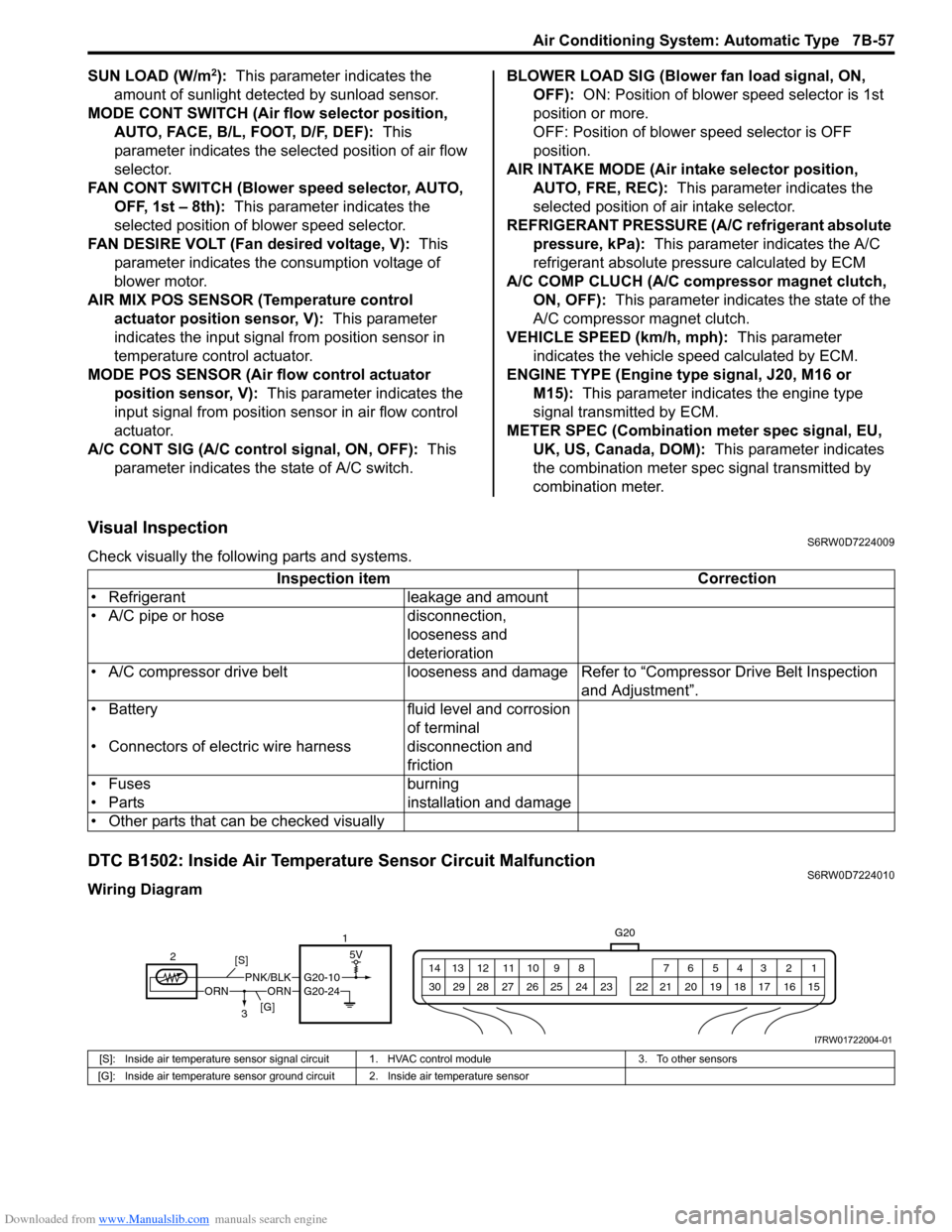
DTC B1502: Inside Air Temperature Sensor Circuit MalfunctionS6RW0D7224010
Wiring DiagramInspection item Correction
• Refrigerant leakage and amount
• A/C pipe or hose disconnection,
looseness and
deterioration
• A/C compressor drive belt looseness and damageRefer to “Compressor Drive Belt Inspection
and Adjustment”.
• Battery fluid level and corrosion
of terminal
• Connectors of electric wire harness disconnection and
friction
• Fuses burning
• Parts installation and damage
• Other parts that can be checked visually
5V
G20
1 2 3 4 5 6 7 8 9 10 11 12 13 14
15 16 17 18 19 20 21 24 23 22 25 26 27 28 29 30
ORNORNPNK/BLKG20-10
21
3 [S]
[G]
G20-24
I7RW01722004-01
[S]: Inside air temperature sensor signal circuit 1. HVAC control module 3. To other sensors
[G]: Inside air temperature sensor ground circuit 2. Inside air temperature sensor
Page 1424 of 1556

Downloaded from www.Manualslib.com manuals search engine 9F-13 Security and Locks:
If check result is not as specified, replace switch.
Replacement of Transmitter Battery (Other than
Keyless Start Model)
S6RW0D9606014
NOTE
For keyless start model, perform
“Replacement of Remote Controller Battery
in Section 10E” instead of “Replacement of
Transmitter Battery (Other than Keyless Start
Model)”.
If transmitter becomes unreliable, replace transmitter
battery as follows.
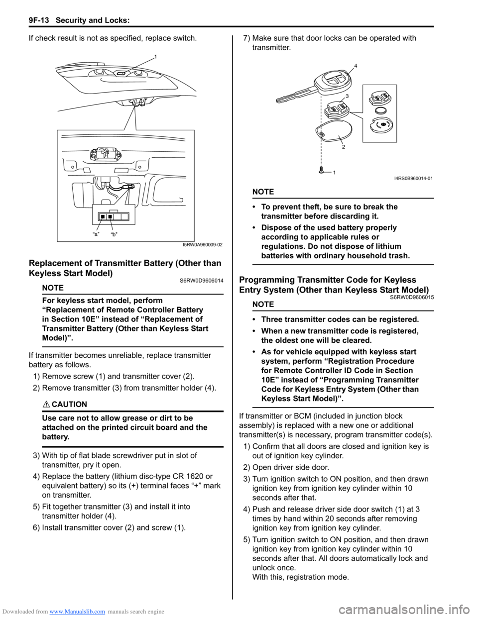
1) Remove screw (1) and transmitter cover (2).
2) Remove transmitter (3) from transmitter holder (4).
CAUTION!
Use care not to allow grease or dirt to be
attached on the printed circuit board and the
battery.
3) With tip of flat blade screwdriver put in slot of
transmitter, pry it open.
4) Replace the battery (lithium disc-type CR 1620 or
equivalent battery) so its (+) terminal faces “+” mark
on transmitter.
5) Fit together transmitter (3) and install it into
transmitter holder (4).
6) Install transmitter cover (2) and screw (1).7) Make sure that door locks can be operated with
transmitter.
NOTE
• To prevent theft, be sure to break the
transmitter before discarding it.
• Dispose of the used battery properly
according to applicable rules or
regulations. Do not dispose of lithium
batteries with ordinary household trash.
Programming Transmitter Code for Keyless
Entry System (Other than Keyless Start Model)
S6RW0D9606015
NOTE
• Three transmitter codes can be registered.
• When a new transmitter code is registered,
the oldest one will be cleared.
• As for vehicle equipped with keyless start
system, perform “Registration Procedure
for Remote Controller ID Code in Section
10E” instead of “Programming Transmitter
Code for Keyless Entry System (Other than
Keyless Start Model)”.
If transmitter or BCM (included in junction block
assembly) is replaced with a new one or additional
transmitter(s) is necessary, program transmitter code(s).
1) Confirm that all doors are closed and ignition key is
out of ignition key cylinder.
2) Open driver side door.
3) Turn ignition switch to ON position, and then drawn
ignition key from ignition key cylinder within 10
seconds after that.
4) Push and release driver side door switch (1) at 3
times by hand within 20 seconds after removing
ignition key from ignition key cylinder.
5) Turn ignition switch to ON position, and then drawn
ignition key from ignition key cylinder within 10
seconds after that. All doors automatically lock and
unlock once.
With this, registration mode.
1
“a”
“b”
I5RW0A960009-02
234
1I4RS0B960014-01
Page 1425 of 1556

Downloaded from www.Manualslib.com manuals search engine Security and Locks: 9F-14
6) Push “UNLOCK” button (2) on transmitter (3) within
20 seconds after Step 5). All doors automatically lock
and unlock once.
With this, code registration is completed.
7) If an additional transmitter, needs to be programed
repeat the procedure of Step 1).
Keyless Entry Answer Back Function Change-
over Procedure (If Equipped)
S6RW0D9606018
Output of keyless entry answer back function can be
switched over by performing the following procedure.
1) Confirm that all doors are closed, all doors are
unlocked, ignition key is out of ignition key cylinder
and interior light switch is in the middle position.
2) Perform Step a) through c) described below within
10 seconds.
a) Insert ignition key in ignition key cylinder.
b) Remove ignition key from ignition key cylinder.
c) Repeat Step a) and b) once.
3) Push “UNLOCK” button on transmitter 3 times within
10 seconds.
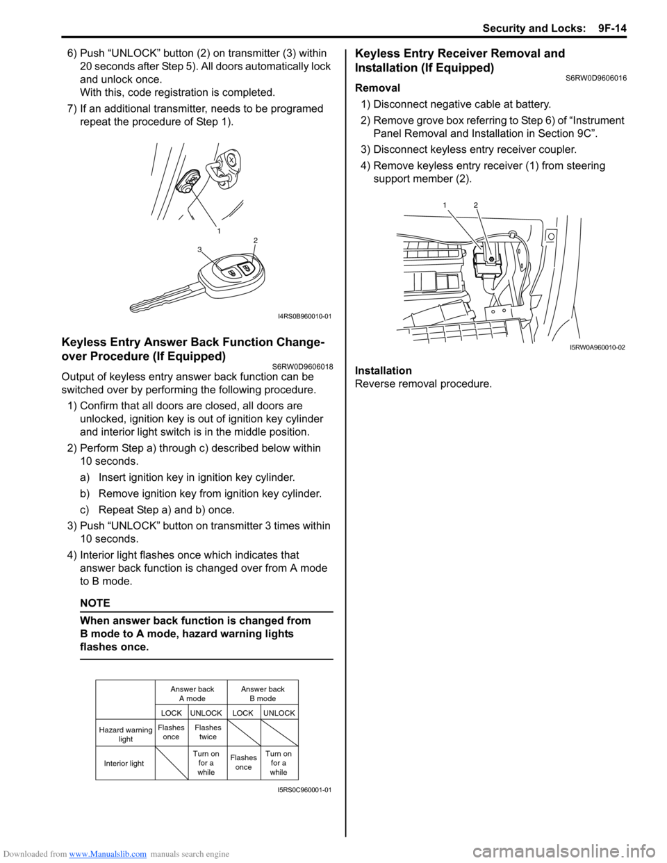
4) Interior light flashes once which indicates that
answer back function is changed over from A mode
to B mode.
NOTE
When answer back function is changed from
B mode to A mode, hazard warning lights
flashes once.
Keyless Entry Receiver Removal and
Installation (If Equipped)
S6RW0D9606016
Removal
1) Disconnect negative cable at battery.
2) Remove grove box referring to Step 6) of “Instrument
Panel Removal and Installation in Section 9C”.
3) Disconnect keyless entry receiver coupler.
4) Remove keyless entry receiver (1) from steering
support member (2).
Installation
Reverse removal procedure.
1
32
I4RS0B960010-01
Hazard warning
light
LOCK LOCKUNLOCK UNLOCK
Interior lightFlashes
onceFlashes
twice
Flashes
once Turn on
for a
whileTurn on
for a
while Answer back
A modeAnswer back
B mode
I5RS0C960001-01
12
I5RW0A960010-02
Page 1502 of 1556

Downloaded from www.Manualslib.com manuals search engine 10B-29 Body Electrical Control System:
5) Disconnect connectors from BCM and junction
block.
6) Detach wiring harness clamp from junction block.
Installation
Reverse removal procedure for installation, noting
following points.
• Connect connectors securely.
• Enable air bag system referring to “Enabling Air Bag
System in Section 8B”.
• With keyless entry system (other than keyless start
model), if BCM is replaced, register transmitter code
into BCM, referring to “Programming Transmitter
Code for Keyless Entry System (Other than Keyless
Start Model) in Section 9F”.
Security Alarm Mode Selection Procedure (If
Equipped)
S6RW0DA206005
Security alarm mode can be selected by performing the
following procedure.
1) Confirm that all doors are closed, all doors are
unlocked and ignition key is inserted in ignition key
cylinder.
2) Remove ignition key from ignition key cylinder.
3) Perform Step a) through e) described below within
15 seconds.
a) Insert ignition key (1) in ignition key cylinder (2).
b) Remove ignition key from ignition key cylinder.
c) Repeat Step a) and b) twice.
d) Insert ignition key in ignition key cylinder.
e) Push lock side (3) of driver side manual lock
switch (4) 3 times.4) When Step 3) is completed, the mode changes to
the next one automatically. The warning buzzer
(located in BCM) sounds by the number of specified
for each mode as follows.
• Changed from A mode to B mode: Buzzer sounds
4 times
• Changed from B mode to A mode: Buzzer sounds
once
Outside Air Temperature Sensor Removal and
Installation
S6RW0DA206002
For removal and installation, refer to “Outside Air
Temperature Sensor Removal and Installation (If
Equipped) in Section 9C”.
Outside Air Temperature Sensor InspectionS6RW0DA206003
For inspection, refer to “Outside Air Temperature Sensor
Inspection (If Equipped) in Section 9C”.
Special Tools and Equipment
Special ToolS6RW0DA208001
1 2
4
3
I7JB01A20007-01
SUZUKI scan tool
—
This kit includes following
items. 1. Tech 2, 2. PCMCIA
card, 3. DLC cable, 4. SAE
16/19 adapter, 5. Cigarette
cable, 6. DLC loop back
adapter, 7. Battery power
cable, 8. RS232 cable, 9.
RS232 adapter, 10. RS232
loop back connector, 11.
Storage case, 12. �)