Cooling System Components SUZUKI SX4 2006 1.G Service User Guide
[x] Cancel search | Manufacturer: SUZUKI, Model Year: 2006, Model line: SX4, Model: SUZUKI SX4 2006 1.GPages: 1556, PDF Size: 37.31 MB
Page 926 of 1556
Downloaded from www.Manualslib.com manuals search engine 7-ii Table of Contents
Compressor Drive Belt Removal and
Installation ....................................................... 7B-31
Compressor Assembly Removal and
Installation ....................................................... 7B-31
Compressor Assembly Components................. 7B-32
Magnet Clutch Inspection.................................. 7B-32
Magnet Clutch Removal and Installation........... 7B-33
Thermal Switch Inspection ................................ 7B-35
Thermal Switch Removal and Installation ......... 7B-35
Relief Valve Inspection...................................... 7B-36
Relief valve Removal and Installation ............... 7B-36
Specifications .....................................................7B-37
Tightening Torque Specifications ...................... 7B-37
Special Tools and Equipment ...........................7B-37
Recommended Service Material ....................... 7B-37
Special Tool ...................................................... 7B-37
Automatic Type .....................................................7B-38
Precautions.........................................................7B-38
A/C System Caution .......................................... 7B-38
Precautions in Diagnosing Trouble ................... 7B-38
Precautions on Servicing A/C System .............. 7B-38
General Description ...........................................7B-39
Auto A/C System Description ............................ 7B-39
HVAC Control Description................................. 7B-40
Sub-Cool A/C System Description .................... 7B-40
On-Board Diagnostic System Description ......... 7B-41
Schematic and Routing Diagram ......................7B-41
A/C System Air Flow Diagram........................... 7B-41
A/C System Wiring Diagram ............................. 7B-42
Component Location .........................................7B-43
A/C System Major Components Location ......... 7B-43
Electronic Control System Components
Location .......................................................... 7B-44
Diagnostic Information and Procedures ..........7B-45
Air Conditioning System Check......................... 7B-45
A/C System Symptom Diagnosis ...................... 7B-47
Abnormal Noise Symptom Diagnosis of A/C
System ............................................................ 7B-49
DTC Check........................................................ 7B-49
DTC Clearance ................................................. 7B-51
DTC Table ......................................................... 7B-52
Fail-Safe Table .................................................. 7B-54
Scan Tool Data ................................................. 7B-55
Visual Inspection ............................................... 7B-57
DTC B1502: Inside Air Temperature Sensor
Circuit Malfunction .......................................... 7B-57
DTC B1503: Evaporator Temperature Sensor
Circuit Malfunction .......................................... 7B-59
DTC B1504: Sunload Sensor Circuit
Malfunction ...................................................... 7B-60
DTC B1511: Temperature Control Actuator
(Position Sensor) and/or Its Circuit
Malfunction ...................................................... 7B-61
DTC B1512: Air flow Control Actuator
(Position Sensor) and/or Its Circuit
Malfunction ...................................................... 7B-63
DTC B1513: Temperature Control Actuator
(Motor) and/or Its Circuit Malfunction .............. 7B-65DTC B1514: Air Flow Control Actuator (Motor)
and/or Its Circuit Malfunction........................... 7B-67
DTC B1520 / B1521 / B1522: Temperature /
Blower Speed / Air Flow Selector
Malfunction ...................................................... 7B-68
DTC B1541: Back-Up Power Supply Circuit
Malfunction ...................................................... 7B-69
DTC B1546: A/C Refrigerant Pressure
Malfunction ...................................................... 7B-70
DTC B1551: Serial Communication Circuit
Malfunction ...................................................... 7B-70
DTC B1552: HVAC Control Module Check
Sum Error ........................................................ 7B-72
DTC B1553: CAN Communication Circuit
Malfunction ...................................................... 7B-72
DTC B1557: VSS Signal Failure ....................... 7B-73
DTC B1561: ECT Signal Failure ....................... 7B-73
DTC B1562: Outside Air Temperature Signal
Failure ............................................................. 7B-74
DTC B1563: A/C Refrigerant Pressure Signal
Failure ............................................................. 7B-74
DTC B1570: Engine Type Signal Failure .......... 7B-75
DTC B1571: Combination Meter Spec Signal
Failure ............................................................. 7B-75
Inspection of HVAC Control Module and Its
Circuit .............................................................. 7B-76
A/C System Inspection at ECM ......................... 7B-79
Repair Instructions ............................................7B-79
Operation Procedure for Refrigerant Charge .... 7B-79
HVAC Unit Components ................................... 7B-80
HVAC Unit Removal and Installation ................ 7B-81
Temperature Control Actuator Removal and
Installation ....................................................... 7B-81
Temperature Control Actuator and Its Circuit
Inspection ........................................................ 7B-81
Air Flow Control Actuator Removal and
Installation ....................................................... 7B-83
Air Flow Control Actuator and Its Circuit
Inspection ........................................................ 7B-83
Air Intake Actuator Removal and Installation .... 7B-84
Air Intake Actuator Inspection ........................... 7B-84
Actuator Linkage Inspection.............................. 7B-84
Blower Motor Controller Removal and
Installation ....................................................... 7B-84
Blower Motor Controller Inspection ................... 7B-85
HVAC Control Module Removal and
Installation ....................................................... 7B-85
Sunload Sensor Removal and Installation ........ 7B-85
Sunload Sensor Inspection ............................... 7B-86
Outside Air Temperature Sensor Removal
and Installation ................................................ 7B-86
Outside Air Temperature Sensor Inspection ..... 7B-86
Inside Air Temperature Sensor Removal and
Installation ....................................................... 7B-86
Inside Air Temperature Sensor Inspection ........ 7B-86
Condenser Cooling Fan Relay Inspection......... 7B-87
Condenser Cooling Fan Removal and
Installation ....................................................... 7B-87
Condenser Cooling Fan Inspection ................... 7B-87
Condenser Assembly On-Vehicle Inspection .... 7B-87
Page 932 of 1556
Downloaded from www.Manualslib.com manuals search engine 7A-4 Heater and Ventilation:
Repair Instructions
HVAC Unit ComponentsS6RW0D7106001
For non-A/C and manual A/C, refer to “HVAC Unit
Components in Section 7B”.
For auto A/C, refer to “HVAC Unit Components in
Section 7B”.
HVAC Unit Removal and Installation (Non-A/C)S6RW0D7106002
For manual A/C and auto A/C, refer to “HVAC Unit
Removal and Installation in Section 7B”.
Removal
1) Drain engine coolant referring to “Cooling System
Draining in Section 1F”, and then disconnect heater
hoses from HVAC unit.
2) Remove cowl top cover from vehicle body referring
to “Cowl Top and Front Lower Crossmember
Components in Section 9K”.
3) Remove instrument panel from vehicle body
referring to “Instrument Panel Removal and
Installation in Section 9C”.
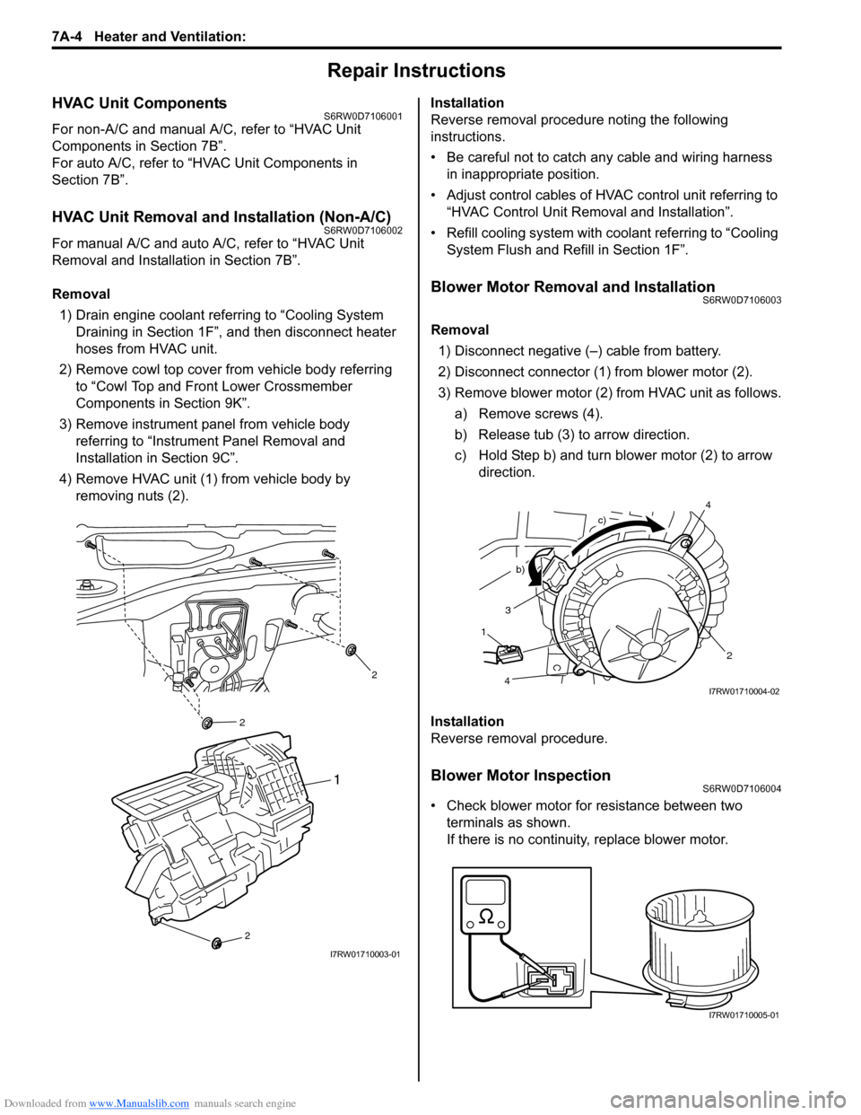
4) Remove HVAC unit (1) from vehicle body by
removing nuts (2).Installation
Reverse removal procedure noting the following
instructions.
• Be careful not to catch any cable and wiring harness
in inappropriate position.
• Adjust control cables of HVAC control unit referring to
“HVAC Control Unit Removal and Installation”.
• Refill cooling system with coolant referring to “Cooling
System Flush and Refill in Section 1F”.
Blower Motor Removal and InstallationS6RW0D7106003
Removal
1) Disconnect negative (–) cable from battery.
2) Disconnect connector (1) from blower motor (2).
3) Remove blower motor (2) from HVAC unit as follows.
a) Remove screws (4).
b) Release tub (3) to arrow direction.
c) Hold Step b) and turn blower motor (2) to arrow
direction.
Installation
Reverse removal procedure.
Blower Motor InspectionS6RW0D7106004
• Check blower motor for resistance between two
terminals as shown.
If there is no continuity, replace blower motor.
2
2
2
1
I7RW01710003-01
3
2
b)
c)
1
4
4I7RW01710004-02
I7RW01710005-01
Page 946 of 1556
Downloaded from www.Manualslib.com manuals search engine 7B-6 Air Conditioning System: Manual Type
Component Location
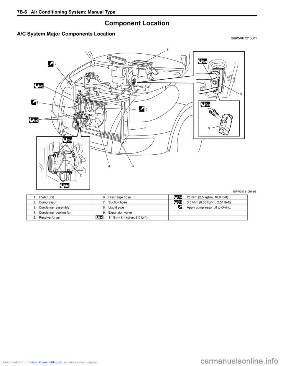
A/C System Major Components LocationS6RW0D7213001
7
8
2435
69
9
(a)
(a)
(a)
(b)
(b)
(c)
1
I7RW01721004-03
1. HVAC unit 6. Discharge hose : 25 N⋅m (2.5 kgf-m, 18.0 lb-ft)
2. Compressor 7. Suction hose : 3.5 N⋅m (0.35 kgf-m, 2.51 lb-ft)
3. Condenser assembly 8. Liquid pipe : Apply compressor oil to O-ring.
4. Condenser cooling fan 9. Expansion valve
5. Receiver/dryer : 11 N⋅m (1.1 kgf-m, 8.0 lb-ft)
Page 947 of 1556
Downloaded from www.Manualslib.com manuals search engine Air Conditioning System: Manual Type 7B-7
Electronic Control System Components LocationS6RW0D7213002
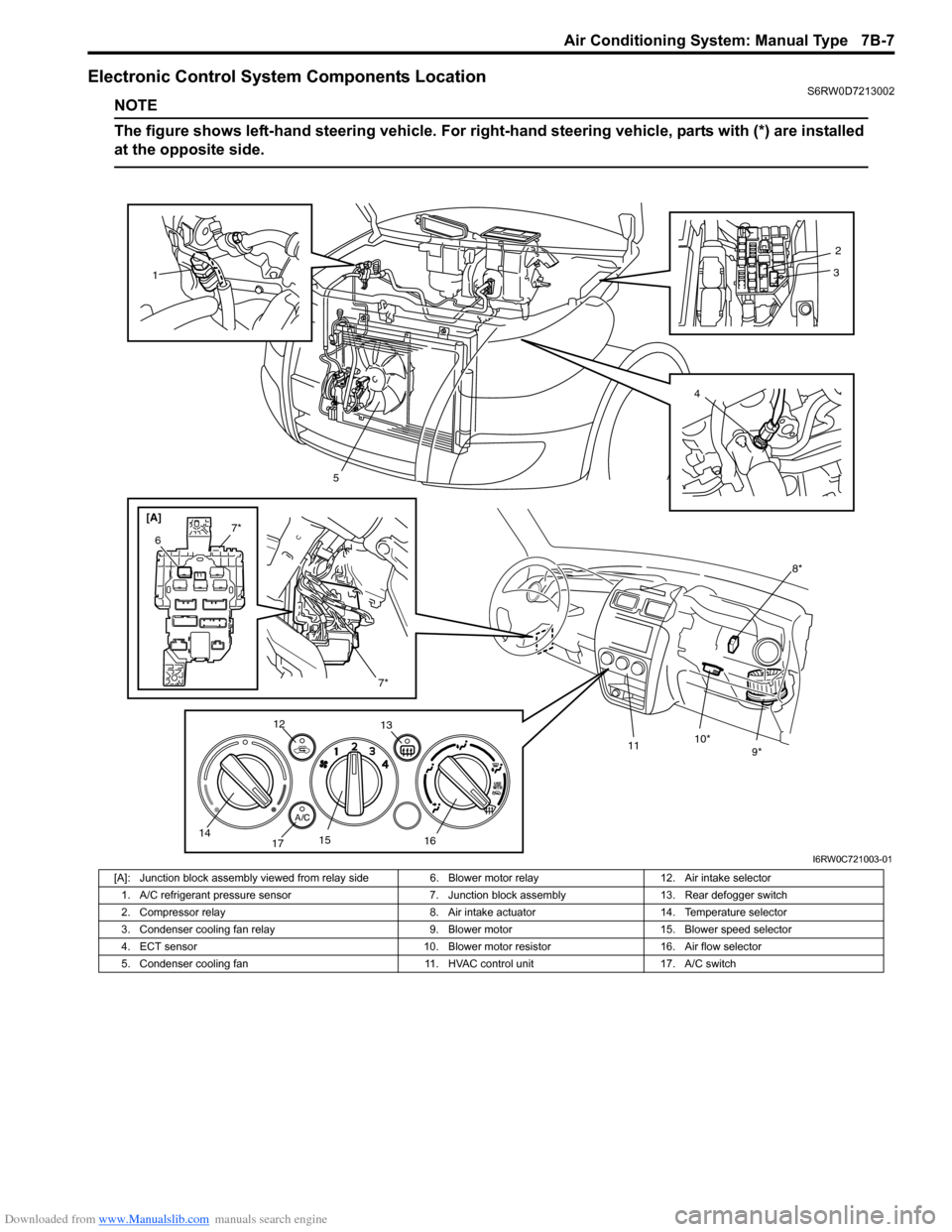
NOTE
The figure shows left-hand steering vehicle. For right-hand steering vehicle, parts with (*) are installed
at the opposite side.
[A]
8*
9* 10*
11
1
5
7*
6
7*
12
13
14
1715
1642
3
I6RW0C721003-01
[A]: Junction block assembly viewed from relay side 6. Blower motor relay 12. Air intake selector
1. A/C refrigerant pressure sensor 7. Junction block assembly 13. Rear defogger switch
2. Compressor relay 8. Air intake actuator 14. Temperature selector
3. Condenser cooling fan relay 9. Blower motor 15. Blower speed selector
4. ECT sensor 10. Blower motor resistor 16. Air flow selector
5. Condenser cooling fan 11. HVAC control unit 17. A/C switch
Page 963 of 1556
Downloaded from www.Manualslib.com manuals search engine Air Conditioning System: Manual Type 7B-23
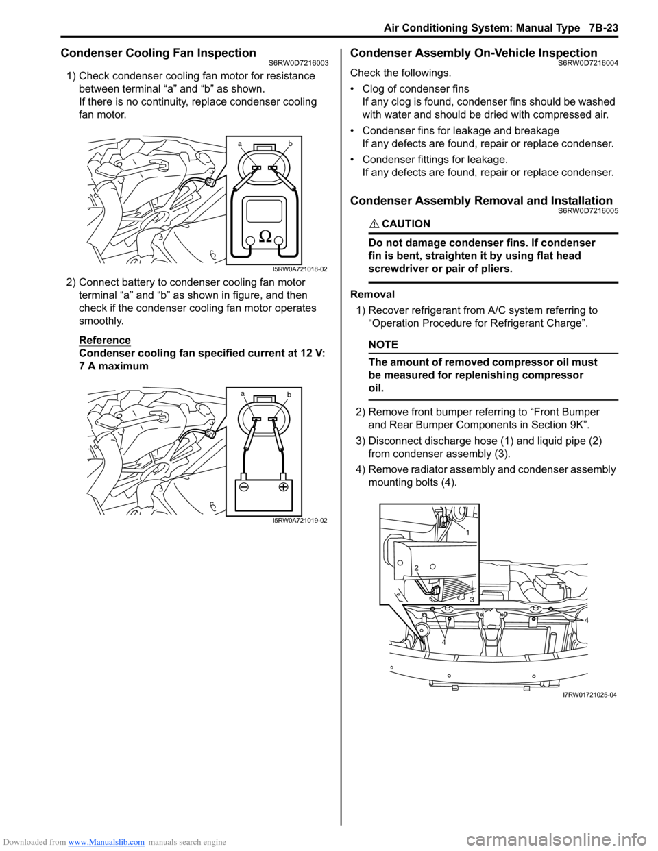
Condenser Cooling Fan InspectionS6RW0D7216003
1) Check condenser cooling fan motor for resistance
between terminal “a” and “b” as shown.
If there is no continuity, replace condenser cooling
fan motor.
2) Connect battery to condenser cooling fan motor
terminal “a” and “b” as shown in figure, and then
check if the condenser cooling fan motor operates
smoothly.
Reference
Condenser cooling fan specified current at 12 V:
7 A maximum
Condenser Assembly On-Vehicle InspectionS6RW0D7216004
Check the followings.
• Clog of condenser fins
If any clog is found, condenser fins should be washed
with water and should be dried with compressed air.
• Condenser fins for leakage and breakage
If any defects are found, repair or replace condenser.
• Condenser fittings for leakage.
If any defects are found, repair or replace condenser.
Condenser Assembly Removal and InstallationS6RW0D7216005
CAUTION!
Do not damage condenser fins. If condenser
fin is bent, straighten it by using flat head
screwdriver or pair of pliers.
Removal
1) Recover refrigerant from A/C system referring to
“Operation Procedure for Refrigerant Charge”.
NOTE
The amount of removed compressor oil must
be measured for replenishing compressor
oil.
2) Remove front bumper referring to “Front Bumper
and Rear Bumper Components in Section 9K”.
3) Disconnect discharge hose (1) and liquid pipe (2)
from condenser assembly (3).
4) Remove radiator assembly and condenser assembly
mounting bolts (4).
ab
I5RW0A721018-02
a
b
I5RW0A721019-02
1
2
3
4
4
I7RW01721025-04
Page 966 of 1556

Downloaded from www.Manualslib.com manuals search engine 7B-26 Air Conditioning System: Manual Type
HVAC Unit Removal and InstallationS6RW0D7216008
Removal
1) Recover refrigerant from A/C system with recovery
and recycling equipment referring to “Recovery” in
“Operation Procedure for Refrigerant Charge”.
2) Drain engine coolant referring to “Cooling System
Draining in Section 1F”, and then disconnect heater
hoses from HVAC unit.
3) Remove cowl top cover from vehicle body referring
to “Cowl Top and Front Lower Crossmember
Components in Section 9K”
4) Remove instrument panel from vehicle body
referring to “Instrument Panel Removal and
Installation in Section 9C”.
5) Loosen a bolt (1) and remove pipes from expansion
valve (2).6) Remove HVAC unit (1) from vehicle body by
removing nuts (2).
7. Cover (without HVAC air
filter)14. Heater core 21. Temperature control lever : Do not reuse.
1
2
I7RW01721016-01
2
2
2
1
I7RW01710003-01
Page 979 of 1556
Downloaded from www.Manualslib.com manuals search engine Air Conditioning System: Automatic Type 7B-39
General Description
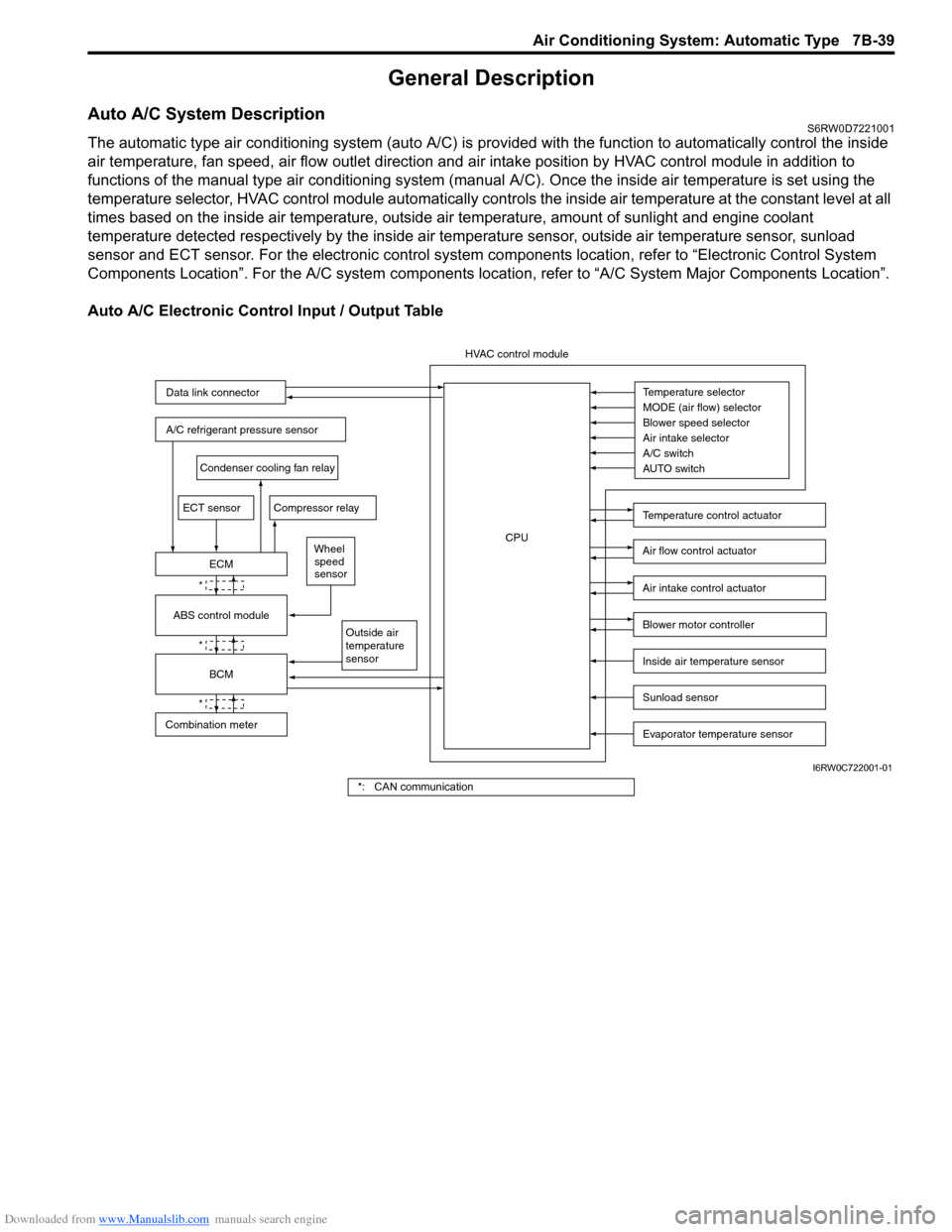
Auto A/C System DescriptionS6RW0D7221001
The automatic type air conditioning system (auto A/C) is provided with the function to automatically control the inside
air temperature, fan speed, air flow outlet direction and air intake position by HVAC control module in addition to
functions of the manual type air conditioning system (manual A/C). Once the inside air temperature is set using the
temperature selector, HVAC control module automatically controls the inside air temperature at the constant level at all
times based on the inside air temperature, outside air temperature, amount of sunlight and engine coolant
temperature detected respectively by the inside air temperature sensor, outside air temperature sensor, sunload
sensor and ECT sensor. For the electronic control system components location, refer to “Electronic Control System
Components Location”. For the A/C system components location, refer to “A/C System Major Components Location”.
Auto A/C Electronic Control Input / Output Table
Temperature selector
MODE (air flow) selector
Blower speed selector
Air intake selector
AUTO switch A/C switch
Outside air
temperature
sensor
A/C refrigerant pressure sensor
Compressor relay
Blower motor controller
Temperature control actuator
Air flow control actuator
Air intake control actuator
BCM
ECM
Data link connector
HVAC control module
CPU
ECT sensor
Sunload sensor
Inside air temperature sensor
Evaporator temperature sensor
Condenser cooling fan relay
Wheel
speed
sensor
*
*
*
Combination meterABS control module
I6RW0C722001-01
*: CAN communication
Page 983 of 1556
Downloaded from www.Manualslib.com manuals search engine Air Conditioning System: Automatic Type 7B-43
Component Location
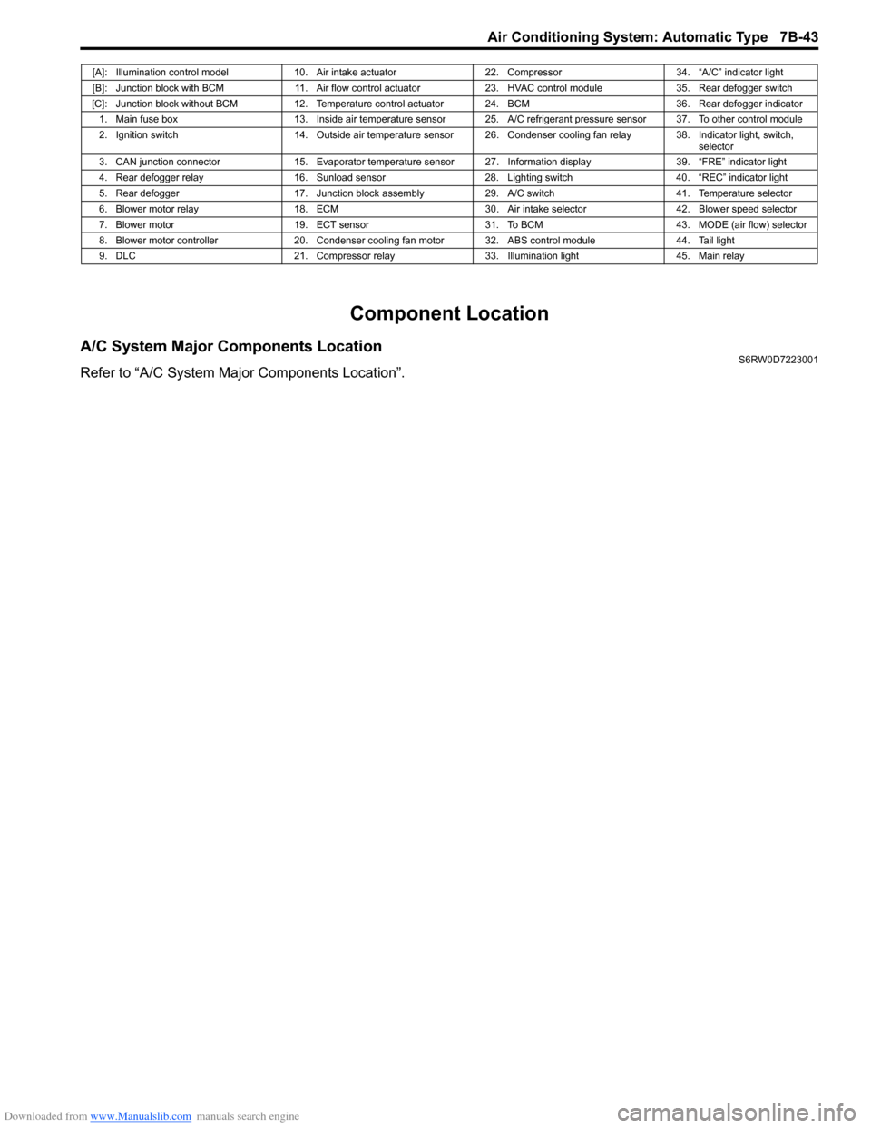
A/C System Major Components LocationS6RW0D7223001
Refer to “A/C System Major Components Location”.
[A]: Illumination control model 10. Air intake actuator 22. Compressor 34. “A/C” indicator light
[B]: Junction block with BCM 11. Air flow control actuator 23. HVAC control module 35. Rear defogger switch
[C]: Junction block without BCM 12. Temperature control actuator 24. BCM 36. Rear defogger indicator
1. Main fuse box 13. Inside air temperature sensor 25. A/C refrigerant pressure sensor 37. To other control module
2. Ignition switch 14. Outside air temperature sensor 26. Condenser cooling fan relay 38. Indicator light, switch,
selector
3. CAN junction connector 15. Evaporator temperature sensor 27. Information display 39. “FRE” indicator light
4. Rear defogger relay 16. Sunload sensor 28. Lighting switch 40. “REC” indicator light
5. Rear defogger 17. Junction block assembly 29. A/C switch 41. Temperature selector
6. Blower motor relay 18. ECM 30. Air intake selector 42. Blower speed selector
7. Blower motor 19. ECT sensor 31. To BCM 43. MODE (air flow) selector
8. Blower motor controller 20. Condenser cooling fan motor 32. ABS control module 44. Tail light
9. DLC 21. Compressor relay 33. Illumination light 45. Main relay
Page 984 of 1556
Downloaded from www.Manualslib.com manuals search engine 7B-44 Air Conditioning System: Automatic Type
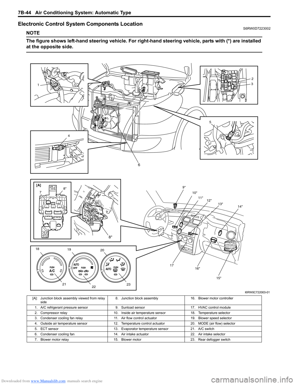
Electronic Control System Components LocationS6RW0D7223002
NOTE
The figure shows left-hand steering vehicle. For right-hand steering vehicle, parts with (*) are installed
at the opposite side.
[A]
2
3
5
1
4
78*
18
19
20
23
22 219*
10*
11*
12*
13*
15* 16* 17
14*
8*6
I6RW0C722003-01
[A]: Junction block assembly viewed from relay
side8. Junction block assembly 16. Blower motor controller
1. A/C refrigerant pressure sensor 9. Sunload sensor 17. HVAC control module
2. Compressor relay 10. Inside air temperature sensor 18. Temperature selector
3. Condenser cooling fan relay 11. Air flow control actuator 19. Blower speed selector
4. Outside air temperature sensor 12. Temperature control actuator 20. MODE (air flow) selector
5. ECT sensor 13. Evaporator temperature sensor 21. A/C switch
6. Condenser cooling fan 14. Air intake actuator 22. Air intake selector
7. Blower motor relay 15. Blower motor 23. Rear defogger switch
Page 1027 of 1556
Downloaded from www.Manualslib.com manuals search engine Air Conditioning System: Automatic Type 7B-87
Condenser Cooling Fan Relay InspectionS6RW0D7226020
Refer to “A/C System Relay Inspection”.
Condenser Cooling Fan Removal and
Installation
S6RW0D7226021
Refer to “Condenser Cooling Fan Removal and
Installation”.
Condenser Cooling Fan InspectionS6RW0D7226022
Refer to “Condenser Cooling Fan Inspection”.
Condenser Assembly On-Vehicle InspectionS6RW0D7226023
Refer to “Condenser Assembly On-Vehicle Inspection”.
Condenser Assembly Removal and InstallationS6RW0D7226024
Refer to “Condenser Assembly Removal and
Installation”.
Evaporator InspectionS6RW0D7226025
Refer to “Evaporator Inspection”.
Evaporator Temperature Sensor Removal and
Installation
S6RW0D7226026
Refer to “Evaporator Temperature Sensor Removal and
Installation”.
Evaporator Temperature Sensor InspectionS6RW0D7226027
Refer to “Evaporator Temperature Sensor Inspection”.
Expansion Valve Removal and InstallationS6RW0D7226028
Refer to “Expansion Valve Removal and Installation”.
Expansion Valve InspectionS6RW0D7226029
Refer to “Expansion Valve Inspection”.
A/C Refrigerant Pressure Sensor and Its Circuit
Inspection
S6RW0D7226030
Refer to “A/C Refrigerant Pressure Sensor and Its Circuit
Inspection”.
A/C Refrigerant Pressure Sensor Removal and
Installation
S6RW0D7226031
Refer to “A/C Refrigerant Pressure Sensor Removal and
Installation”.
Compressor Relay InspectionS6RW0D7226032
Refer to “A/C System Relay Inspection”.
Compressor Drive Belt Inspection and
Adjustment
S6RW0D7226033
Refer to “Compressor Drive Belt Inspection and
Adjustment”.
Compressor Drive Belt Removal and
Installation
S6RW0D7226034
Refer to “Compressor Drive Belt Removal and
Installation”.
Compressor Assembly Removal and
Installation
S6RW0D7226035
Refer to “Compressor Assembly Removal and
Installation”.
Compressor Assembly ComponentsS6RW0D7226036
Refer to “Compressor Assembly Components”.
Magnet Clutch Removal and InstallationS6RW0D7226037
Refer to “Magnet Clutch Removal and Installation”.
Magnet Clutch InspectionS6RW0D7226038
Refer to “Magnet Clutch Inspection”.
Thermal Switch InspectionS6RW0D7226039
Refer to “Thermal Switch Inspection”.
Thermal Switch Removal and InstallationS6RW0D7226040
Refer to “Thermal Switch Removal and Installation”.
Relief Valve InspectionS6RW0D7226041
Refer to “Relief Valve Inspection”.