G-1 SUZUKI SX4 2006 1.G Service User Guide
[x] Cancel search | Manufacturer: SUZUKI, Model Year: 2006, Model line: SX4, Model: SUZUKI SX4 2006 1.GPages: 1556, PDF Size: 37.31 MB
Page 394 of 1556
Downloaded from www.Manualslib.com manuals search engine 1G-17 Fuel System:
Fuel Pump InspectionS6RW0D1706016
• Check fuel pump assembly for damage.
• Check fuel suction filter for evidence of dirt and
contamination.
If present, replace or clean and check for presence of
dirt in fuel tank.
• For electrical circuit, refer to “Fuel Pump and Its
Circuit Check in Section 1A”.
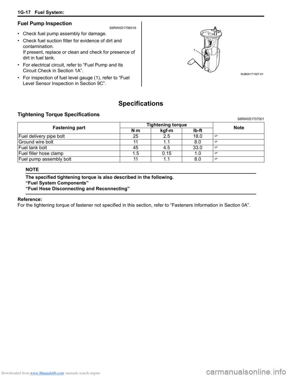
• For inspection of fuel level gauge (1), refer to “Fuel
Level Sensor Inspection in Section 9C”.
Specifications
Tightening Torque SpecificationsS6RW0D1707001
NOTE
The specified tightening torque is also described in the following.
“Fuel System Components”
“Fuel Hose Disconnecting and Reconnecting”
Reference:
For the tightening torque of fastener not specified in this section, refer to “Fasteners Information in Section 0A”.
1
I5JB0A171027-01
Fastening partTightening torque
Note
N⋅mkgf-mlb-ft
Fuel delivery pipe bolt 25 2.5 18.0�)
Ground wire bolt 11 1.1 8.0�)
Fuel tank bolt 45 4.5 33.0�)
Fuel filler hose clamp 1.5 0.15 1.0�)
Fuel pump assembly bolt 11 1.1 8.0�)
Page 395 of 1556

Downloaded from www.Manualslib.com manuals search engine Fuel System: 1G-18
Special Tools and Equipment
Special ToolS6RW0D1708001
09912–57610 09912–58421
Injector checking tool plate Checking tool set
�)This kit includes the
following items. 1. Tool body
and washer, 2. Body plug, 3.
Body attachment-1, 4.
Holder, 5. Return hose and
clamp, 6. Body attachment-2
and washer, 7. Hose
attachment-1, 8. Hose
attachment-2 �)
09912–58432 09912–58442
Fuel pressure gauge hose Fuel pressure gauge
This tool is included in fuel
pressure gauge set (09912-
58413). �)This tool is included in fuel
pressure gauge set (09912-
58413). �)
09912–58490 09919–47020
3-way joint & hose Quick joint remover
�)�)
09930–88530 SUZUKI scan tool (SUZUKI-
SDT)
Injector test lead —
�)This kit includes following
items. 1. SUZUKI-SDT 2.
DLC3 cable 3. USB cable 4.
AC/DC power supply 5.
Voltage meter probe 6.
Storage case �)
1
2
34
56
Page 1162 of 1556
Downloaded from www.Manualslib.com manuals search engine 9-ii Table of Contents
B-9 Keyless Start System Circuit Diagram...... 9A-103
C-1 Combination Meter Circuit Diagram
(Meter) .......................................................... 9A-104
C-2 Combination Meter Circuit Diagram
(Indicator) ...................................................... 9A-105
C-3 Combination Meter Circuit Diagram
(Warning Light) ............................................. 9A-106
D-1 Headlight System Circuit Diagram
(Except Taiwan) ............................................ 9A-108
D-1 Headlight System Circuit Diagram
(Taiwan) ........................................................ 9A-110
D-2 Position, Tail and Licence Plate Light
System Circuit Diagram (Except Taiwan) ..... 9A-111
D-2 Position, Tail and Licence Plate Light
System Circuit Diagram (Taiwan) ................. 9A-112
D-3 Front Fog Light System Circuit Diagram
(Except Taiwan) ............................................ 9A-113
D-3 Front Fog Light System Circuit Diagram
(Taiwan) ........................................................ 9A-114
D-4 Illumination Light System Circuit Diagram
(Except Taiwan) ............................................ 9A-115
D-4 Illumination Light System Circuit Diagram
(Taiwan) ........................................................ 9A-116
D-5 Interior Light System Circuit Diagram
(Except Taiwan) ............................................ 9A-117
D-5 Interior Light System Circuit Diagram
(Taiwan) ........................................................ 9A-118
D-6 Turn Signal and Hazard Warning Light
System Circuit Diagram (Except Taiwan) ..... 9A-119
D-6 Turn Signal and Hazard Warning Light
System Circuit Diagram (Taiwan) ................. 9A-121
D-7 Brake Light System Circuit Diagram ........ 9A-123
D-8 Back-Up Light System Circuit Diagram .... 9A-124
D-9 Headlight Beam Leveling System Circuit
Diagram (Manual Leveling)........................... 9A-125
D-10 Rear Fog Light Circuit Diagram .............. 9A-126
E-1 Heater System Circuit Diagram ................ 9A-127
E-2 Auto A/C System Circuit Diagram ............ 9A-129
F-1 Air-Bag System Circuit Diagram (4ch) ...... 9A-131
F-1 Air-Bag System Circuit Diagram (8ch) ...... 9A-132
F-2 Anti-Lock Brake System Circuit Diagram.. 9A-134
F-4 Power Steering System Circuit Diagram .. 9A-136
G-1 Audio System Circuit Diagram ................. 9A-138
G-2 Multi Information Display / Accessory
Socket System Circuit Diagram .................... 9A-140
G-4 Navigation System Circuit Diagram ......... 9A-141
List of Connector .............................................9A-143
List of Connectors ........................................... 9A-143
C Connector .................................................... 9A-143
E Connector .................................................... 9A-145
G Connector .................................................... 9A-146
J Connector ..................................................... 9A-149
K Connector .................................................... 9A-149
L Connector..................................................... 9A-150
O Connector .................................................... 9A-152
Q Connector (8ch)........................................... 9A-152
R Connector .................................................... 9A-152
S Connector .................................................... 9A-152
Lighting Systems .................................... 9B-1
Precautions ...........................................................9B-1
Precautions for Discharge Headlight Service
(If Equipped)...................................................... 9B-1
Precautions in Diagnosing Troubles
(Headlight Auto Leveling System) ..................... 9B-1
General Description .............................................9B-1
Discharge Headlight Description (If
Equipped) .......................................................... 9B-1
Headlight Auto Leveling System Description
(If Equipped)...................................................... 9B-2
Auto-On Headlight System Description (If
Equipped) .......................................................... 9B-4
Schematic and Routing Diagram ........................9B-5
Headlight Auto Leveling System Wiring
Circuit Diagram ................................................. 9B-5
Component Location ...........................................9B-6
Lighting System Components Location............... 9B-6
Interior Light System Location............................. 9B-7
Diagnostic Information and Procedures ............9B-7
Self-Diagnosis Function for Headlight Auto
Leveling System ................................................ 9B-7
Headlight Leveling Warning Light Check ............ 9B-8
Headlight Symptom Diagnosis (Discharge
Headlight Model) ............................................... 9B-8
Headlight Symptom diagnosis (Other than
Discharge Headlight Model) .............................. 9B-9
Auto-On Headlight System Symptom
Diagnosis (If Equipped) ..................................... 9B-9
DRL System Symptom Diagnosis (If
Equipped) ........................................................ 9B-10
Headlight Auto Leveling System Symptom
Diagnosis (If Equipped) ................................... 9B-10
Headlight Manual Leveling System Symptom
Diagnosis (If Equipped) ................................... 9B-10
Turn Signal and Hazard Warning Light
Symptom Diagnosis ........................................ 9B-11
Clearance, Tail and License Plate Light
Symptom Diagnosis ........................................ 9B-11
Back-Up Light Symptom Diagnosis................... 9B-12
Brake Light Symptom Diagnosis ....................... 9B-12
Front Fog Light Symptom Diagnosis (If
Equipped) ........................................................ 9B-12
Rear Fog Light Symptom Diagnosis (If
Equipped) ........................................................ 9B-12
Illumination Cancel System Symptom
Diagnosis (If Equipped) ................................... 9B-13
Interior Light Symptom Diagnosis ..................... 9B-13
DRL Operation Inspection (If Equipped) ........... 9B-13
Inspection of DRL Controller and Its Circuits
(If Equipped).................................................... 9B-13
Auto-On Headlight Operation Inspection (If
Equipped) ........................................................ 9B-15
Inspection of Auto-On Headlight Controller
and Its Circuit (If Equipped)............................. 9B-15
Inspection of Headlight Leveling Control
Module and Its Circuit (Headlight Auto
Leveling System)............................................. 9B-16
Repair Instructions ............................................9B-18
Headlight Housing Removal and Installation .... 9B-18
Page 1165 of 1556
Downloaded from www.Manualslib.com manuals search engine Table of Contents 9-v
Power Door Lock System Symptom
Diagnosis (If Equipped)..................................... 9F-3
Power Door Lock System Operation
Inspection (If Equipped) .................................... 9F-3
Keyless Entry System Symptom Diagnosis (If
Equipped).......................................................... 9F-4
Keyless Entry System Operation Inspection
(If Equipped) ..................................................... 9F-5
Door Lock Function of Keyless Start System
Symptom Diagnosis (If Equipped) .................... 9F-5
Rear End Door Opener System Symptom
Diagnosis (If Equipped)..................................... 9F-5
Rear End Door Opener System Operation
Inspection (If Equipped) .................................... 9F-5
Repair Instructions .............................................. 9F-6
Front Door Lock Assembly Components ............ 9F-6
Front Door Lock Assembly Removal and
Installation ......................................................... 9F-6
Front Door Lock Assembly Inspection ................ 9F-8
Power Door Lock Switch Inspection (If
Equipped).......................................................... 9F-8
Door Key Cylinder Switch Inspection (If
Equipped).......................................................... 9F-8
Power Door Lock Actuator Inspection (If
Equipped).......................................................... 9F-9
Rear Door Lock Assembly Components ........... 9F-10
Rear Door Lock Assembly Removal and
Installation ....................................................... 9F-10
Rear Door Lock Assembly Inspection ............... 9F-10
Rear End Door Lock Assembly Components.... 9F-11
Rear End Door Lock Assembly Removal and
Installation ....................................................... 9F-12
Rear End Door Lock Assembly Inspection........ 9F-12
Rear End Door Opener Switch Inspection (If
Equipped)........................................................ 9F-12
Replacement of Transmitter Battery (Other
than Keyless Start Model) ............................... 9F-13
Programming Transmitter Code for Keyless
Entry System (Other than Keyless Start
Model) ............................................................. 9F-13
Keyless Entry Answer Back Function
Change-over Procedure (If Equipped) ............ 9F-14
Keyless Entry Receiver Removal and
Installation (If Equipped)................................. 9F-14
Keyless Entry Receiver and Its Circuit
Inspection (If Equipped) .................................. 9F-15
Specifications..................................................... 9F-16
Tightening Torque Specifications ...................... 9F-16
Special Tools and Equipment ........................... 9F-16
Recommended Service Material ....................... 9F-16
Seats ......................................................... 9G-1
Diagnostic Information and Procedures ............9G-1
Front Seat Heater Symptom Diagnosis (If
Equipped)..........................................................9G-1
Repair Instructions ..............................................9G-2
Front Seat Components ......................................9G-2
Front Seat Removal and Installation ...................9G-3Front Seat Heater Switch (Driver and
Passenger Side) Inspection (If Equipped)........ 9G-3
Front Seat Heater Wire Inspection (If
Equipped) ......................................................... 9G-3
Rear Seat Components...................................... 9G-4
Rear Seat Removal and Installation................... 9G-4
Specifications ...................................................... 9G-5
Tightening Torque Specifications ....................... 9G-5
Special Tools and Equipment ............................ 9G-5
Recommended Service Material ........................ 9G-5
Interior Trim ............................................. 9H-1
Repair Instructions ..............................................9H-1
Floor Carpet Removal and Installation ................9H-1
Head Lining Removal and Installation.................9H-2
Console Box Components ..................................9H-3
Specifications .......................................................9H-4
Tightening Torque Specifications ........................9H-4
Hood / Fenders / Doors ............................ 9J-1
Repair Instructions .............................................. 9J-1
Hood Removal and Installation ........................... 9J-1
Hood Inspection and Adjustment ........................ 9J-1
Front Fender Components .................................. 9J-2
Front Fender Removal and Installation ............... 9J-2
Front Door Assembly Components ..................... 9J-3
Front Door Assembly Removal and
Installation ......................................................... 9J-3
Rear Door Assembly Components...................... 9J-5
Rear Door Assembly Removal and
Installation ......................................................... 9J-5
Rear End Door Assembly Components .............. 9J-6
Rear End Door Assembly Removal and
Installation ......................................................... 9J-6
Specifications ....................................................... 9J-8
Tightening Torque Specifications ........................ 9J-8
Special Tools and Equipment ............................. 9J-8
Recommended Service Material ......................... 9J-8
Body Structure......................................... 9K-1
Repair Instructions ..............................................9K-1
Front Bumper and Rear Bumper Components .... 9K-1
Cowl Top and Front Lower Crossmember
Components ...................................................... 9K-2
Specifications .......................................................9K-3
Body Dimensions ................................................ 9K-3
Panel Clearance................................................ 9K-10
Tightening Torque Specifications ...................... 9K-10
Paint / Coatings ........................................9L-1
General Description ............................................. 9L-1
Anti-Corrosion Treatment Construction............... 9L-1
Plastic Parts Finishing ......................................... 9L-2
Component Location ........................................... 9L-3
Sealant Application Areas ................................... 9L-3
Under Coating Application Areas ...................... 9L-10
Anti-Corrosion Compound Application Area ..... 9L-12
Exterior Trim ............................................ 9M-1
Page 1224 of 1556
Downloaded from www.Manualslib.com manuals search engine 9A-57 Wiring Systems:
System Circuit Diagram
System Circuit DiagramS6RW0D910E001
Refer to “A-1 Cranking System Circuit Diagram”.
Refer to “A-2 Charging System Circuit Diagram”.
Refer to “A-3 Ignition System Circuit Diagram (M15A engine, M16A engine)”.
Refer to “A-3 Ignition System Circuit Diagram (J20A engine)”.
Refer to “A-4 Cooling System Circuit Diagram (M15A engine, M16A engine)”.
Refer to “A-4 Cooling System Circuit Diagram (J20A engine)”.
Refer to “A-5 Engine and A/C Control System Circuit Diagram (M15A engine)”.
Refer to “A-5 Engine and A/C Control System Circuit Diagram (M16A engine)”.
Refer to “A-5 Engine and A/C Control System Circuit Diagram (J20A engine)”.
Refer to “A-6 A/T Control System Circuit Diagram”.
Refer to “A-7 Immobilizer System Circuit Diagram”.
Refer to “A-8 Body Control System Circuit Diagram (Except Taiwan)”.
Refer to “A-8 Body Control System Circuit Diagram (Taiwan)”.
Refer to “A-10 4WD Control System (Except Taiwan)”
Refer to “B-1 Windshield Wiper and Washer Circuit Diagram”.
Refer to “B-2 Rear Wiper and Washer Circuit Diagram (Except Taiwan)”.
Refer to “B-2 Rear Wiper and Washer Circuit Diagram (Taiwan)”.
Refer to “B-3 Rear Defogger Circuit Diagram (Except Taiwan)”.
Refer to “B-3 Rear Defogger Circuit Diagram (Taiwan)”.
Refer to “B-4 Power Window Circuit Diagram”.
Refer to “B-5 Power Door Lock Circuit Diagram (Except Taiwan)”.
Refer to “B-5 Power Door Lock Circuit Diagram (Taiwan)”.
Refer to “B-6 Power Mirror Circuit Diagram (Except Taiwan)”.
Refer to “B-6 Power Mirror Circuit Diagram (Taiwan)”.
Refer to “B-7 Horn Circuit Diagram”.
Refer to “B-8 Seat Heater Circuit Diagram”.
Refer to “B-9 Keyless Start System Circuit Diagram”
Refer to “C-1 Combination Meter Circuit Diagram (Meter)”.
Refer to “C-2 Combination Meter Circuit Diagram (Indicator)”.
Refer to “C-3 Combination Meter Circuit Diagram (Warning Light)”.
Refer to “D-1 Headlight System Circuit Diagram (Except Taiwan)”.
Refer to “D-1 Headlight System Circuit Diagram (Taiwan)”.
Refer to “D-2 Position, Tail and Licence Plate Light System Circuit Diagram (Except Taiwan)”.
Refer to “D-2 Position, Tail and Licence Plate Light System Circuit Diagram (Taiwan)”.
Refer to “D-3 Front Fog Light System Circuit Diagram (Except Taiwan)”.
Refer to “D-3 Front Fog Light System Circuit Diagram (Taiwan)”.
Refer to “D-4 Illumination Light System Circuit Diagram (Except Taiwan)”.
Refer to “D-4 Illumination Light System Circuit Diagram (Taiwan)”.
Refer to “D-5 Interior Light System Circuit Diagram (Except Taiwan)”.
Refer to “D-5 Interior Light System Circuit Diagram (Taiwan)”.
Refer to “D-6 Turn Signal and Hazard Warning Light System Circuit Diagram (Except Taiwan)”.
Refer to “D-6 Turn Signal and Hazard Warning Light System Circuit Diagram (Taiwan)”.
Refer to “D-7 Brake Light System Circuit Diagram”.
Refer to “D-8 Back-Up Light System Circuit Diagram”.
Refer to “D-9 Headlight Beam Leveling System Circuit Diagram (Manual Leveling)”.
Refer to “D-10 Rear Fog Light Circuit Diagram”.
Refer to “E-1 Heater System Circuit Diagram”.
Refer to “E-2 Auto A/C System Circuit Diagram”.
Refer to “F-1 Air-Bag System Circuit Diagram (4ch)”.
Refer to “F-1 Air-Bag System Circuit Diagram (8ch)”.
Refer to “F-2 Anti-Lock Brake System Circuit Diagram”.
Refer to “F-4 Power Steering System Circuit Diagram”.
Refer to “G-1 Audio System Circuit Diagram”.
Refer to “G-2 Multi Information Display / Accessory Socket System Circuit Diagram”.
Refer to “G-4 Navigation System Circuit Diagram”.
Page 1248 of 1556
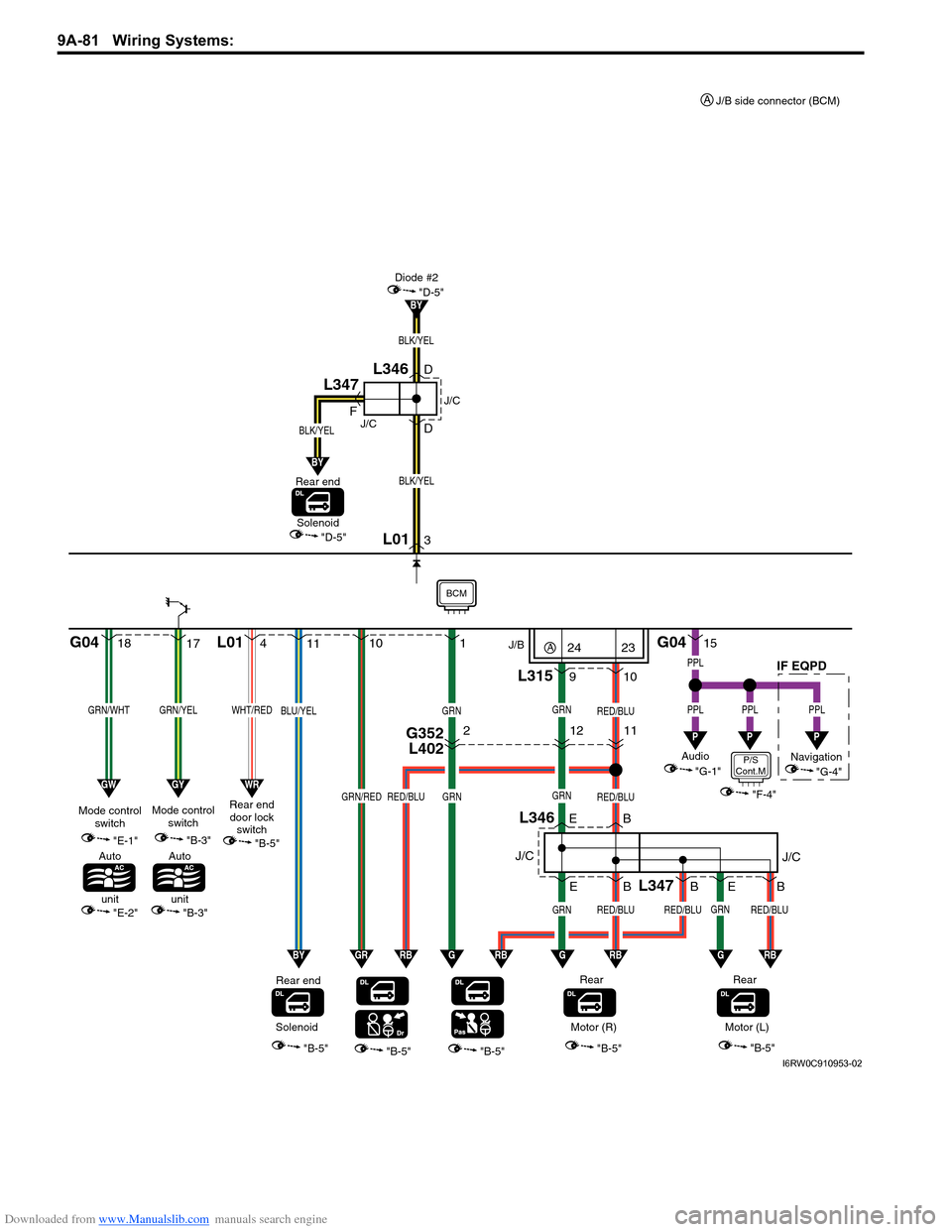
Downloaded from www.Manualslib.com manuals search engine 9A-81 Wiring Systems:
1817
GRN/WHTGRN/YEL
"E-1"
"E-2"
Mode control
switch
Auto
unit
G04 L01
"B-5""B-5""B-5""B-5"
11
9
L346
10
B E E
Rear
GRN
GRN
RED/BLU
GRNRED/BLU
B
L347
RED/BLUGRNRED/BLU
GRN
RED/BLU
B 1
10
B E
GRN/REDRED/BLU
BLU/YELGRN
Rear end
4
WHT/RED
Rear end
door lock
switch
3 D
D F
"D-5"
BLK/YEL
L01
Diode #2
BY
GWGYWR
G04
L31515
PPL
PPL
P
PPL
P
PPL
P
BYGRRBGGRBGRBGRB
"B-5"
Audio J/B
"G-1"Navigation
"G-4"
SolenoidMotor (R)
"B-5"
Rear
Motor (L)
J/CIF EQPDJ/C
"B-3"
Mode control
switch
BCM
BLK/YEL
BY
BLK/YEL
"D-5"Solenoid
Rear end
J/C
J/C
L346
L347
"B-3"
Auto
unit
G352
L40221211
P/S
Cont.M
"F-4"
24A23
J/B side connector (BCM) A
I6RW0C910953-02
Page 1252 of 1556

Downloaded from www.Manualslib.com manuals search engine 9A-85 Wiring Systems:
620
GRN/WHTGRN/YEL
"E-1"
"E-2"
Mode control
switch
Auto
unit
G05 G04 G05 G06
"B-5""B-5""B-5""B-5"
72
L346
3
B E E
Rear
GRN
GRN
RED/BLU
GRNRED/BLU
B
L347
RED/BLUGRNRED/BLU
GRN
RED/BLU
B 9
8
B E
GRN/REDRED/BLUBLU/YEL
BLU/YELGRN
Rear end
30
WHT/RED
Rear end
door lock
switch
29 D
D F
"D-5"
BLK/YEL
BLK/YEL
G05
Diode #2 Relay
BY
GWGYWR
G0422
PPL
PPL
P
PPL
P
BYGRRBGGRBGRBGRB
"B-5"
Audio
"G-1"
SolenoidMotor (R)
"B-5"
Rear
Motor (L)
J/CJ/C
"B-3"
Mode control
switch
BCM
BLK/YEL
BY
BLK/YEL
"D-5"Solenoid
Rear end
J/C
J/C
L346
L347
"B-3"
Auto
unit
L376
G34316
17
"D-3"
BLK
BLK
B
E381
G33313
G352
L4023G352
L40221211
P/S
Cont.M
"F-4"
I6RW0C910957-01
Page 1253 of 1556
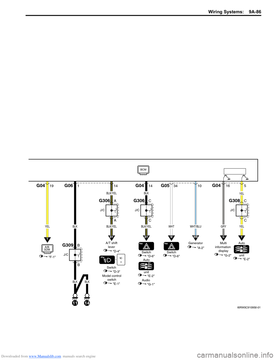
Downloaded from www.Manualslib.com manuals search engine Wiring Systems: 9A-86
19G041
B
BG06
11
J/C
G309
A
A
J/C
G306
BLK
14
BLK
"F-1"
YELBLK
A/B
SDM
Switch
Auto
unit"D-6"
Model control
switch
"E-1""E-2"
A/T shift
lever
"D-4"
Switch
"D-3"
Audio
"G-1"
Y
G0434G05
WHT
W
14
BLK/YEL
BLK/YEL
BY
C
C
J/C
G306
14
BLK/YEL
C
C
J/C
G308
YEL
BLK
BY
"A-2" Generator
10
WHT/BLU
WB
5
YEL
Y
GRY
16G04
G
"G-2" Multi
information
display
BCM
Auto
unit
"E-2"
Switch
"D-6"
I6RW0C910958-01
Page 1282 of 1556
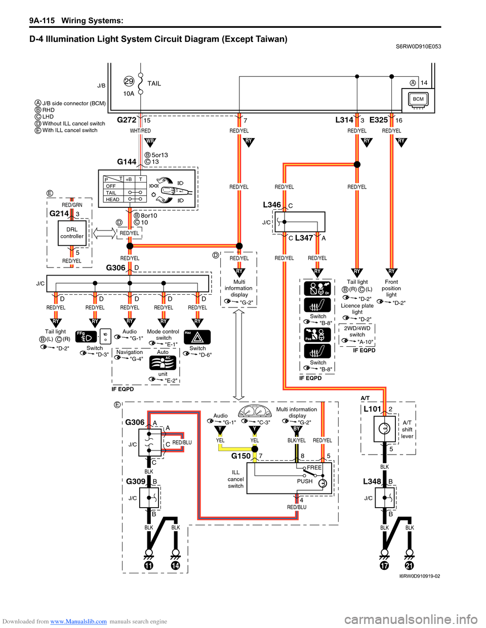
Downloaded from www.Manualslib.com manuals search engine 9A-115 Wiring Systems:
D-4 Illumination Light System Circuit Diagram (Except Taiwan)S6RW0D910E053
BLKBLK
BLK
RED/BLU
RED/BLU
11
J/C
J/C
B
B
14
G309
A
A
C
CG306
BLK/YELRED/YEL
BY
YELYEL
YY
Multi information
display
"G-2"Audio
"G-1""C-3"
ILL
cancel
switch
G150758
4
PUSHFREE
WHT/RED
10ATAIL
29J/B
15G272
G144
1721
RED/YELRED/YELRED/YEL
RED/YELRED/YEL
L3143
BLKBLK
BLK
"D-3"
A/T
RY
Switch
J/C
G306
RED/YEL
RY
RED/YEL
Switch
Auto
unit
IF EQPDIF EQPDIF EQPD
RY
RED/YEL
Mode control
switch
"E-1"Tail light
(L)
"D-2"
"E-2"
"D-6"Switch"B-8"
Switch"B-8"
OFF
TAIL
HEAD+BT T
P
7
RY
RED/YEL
Audio
"G-1"
Navigation
"G-4"
D
D
D D D
RY
RED/YEL
D
RED/YEL
Multi
information
display
"G-2"
RED/YEL
RYRYRY
RYRYWR
Tail light
"D-2"Front
position
light
"D-2"
Licence plate
light
"D-2"
2WD/4WD
switch
"A-10"
RED/YELRED/YEL
RED/YEL
E32516
RY
RY
J/C
B
BL348
J/C
C
C
A
L346
L347
A/T
shift
lever
L1012
5
5or13
13BC
8or10
10BC
J/B side connector (BCM)
RHD
LHD
Without ILL cancel switch
With ILL cancel switch ABCDE
B(R)
C
(R)
B(L)
C
BCM
14A
RED/YEL
D
D
E
DRL
controller
G2143
5
RED/YEL
RED/GRN
E
I6RW0D910919-02
Page 1283 of 1556

Downloaded from www.Manualslib.com manuals search engine Wiring Systems: 9A-116
D-4 Illumination Light System Circuit Diagram (Taiwan)S6RW0D910E025
BLU/WHT
RED/YEL
10ATAIL
36
J/B
12G272
10
G14413
131721
RED/YELRED/YEL
RED/YELRED/YELRED/YEL
L3143
BLKBLK
BLKBLK
"D-3"
A/T
RY
Switch
J/C
G306
RED/YEL
RY
RED/YEL
Switch
Auto
unit
RY
RED/YEL
Mode control
switch
"E-1"Tail light
(R)
"D-2"
"E-2"
"D-6"
OFF
TAIL
HEAD+BT T
P
187
RY
RED/YEL
Audio
"G-1"
D
D
D D D
RY
RED/YEL
D
RED/YEL
Multi
information
display
"G-2"
RED/YEL
RYRY
RYRY
RY
Tail light (L)
"D-2"Front
position
light
"D-2"
Licence plate
light
"D-2"
RED/YEL
RED/YEL
E32516
RY
RY
J/C
B
BL348
J/C
C
CL346
A/T
shift
lever
L1012
5
2 1
3
4
Tail light
relay
11
G05
G0412
BCM
I6RW0C910985-01