Manual Transaxle Oil Inspection SUZUKI SX4 2006 1.G Service User Guide
[x] Cancel search | Manufacturer: SUZUKI, Model Year: 2006, Model line: SX4, Model: SUZUKI SX4 2006 1.GPages: 1556, PDF Size: 37.31 MB
Page 666 of 1556
Downloaded from www.Manualslib.com manuals search engine 5A-18 Automatic Transmission/Transaxle:
Step 2. DTC / Freeze Frame Data Check, Record and
Clearance
First, referring to “DTC Check”, check DTC and pending
DTC. If DTC exists, print or write down DTC and freeze
frame data and then clear malfunction DTC(s) by
referring to “DTC Clearance”. Malfunction DTC indicates
malfunction in the system but it is not possible to know
from it whether the malfunction is occurring now or it
occurred in the past and normal condition has been
restored. In order to know that, check symptom in
question according to Step 5 and then recheck DTC
according to Step 6.
Diagnosing a trouble based on the DTC in this step only
or failure to clear the DTC in this step may result in an
faulty diagnosis, trouble diagnosis of a normal circuit or
difficulty in troubleshooting which is otherwise
unnecessary.
Step 3 and 4. Visual Inspection
As a preliminary step, be sure to perform visual check of
the items that support proper function of the engine and
automatic transaxle referring to “Visual Inspection”.
Step 5. Trouble Symptom Confirmation
Check trouble symptoms based on information obtained
in “Step 1. Customer Complaint Analysis: ” and “Step 2.
DTC / Freeze Frame Data Check, Record and
Clearance: ”.
Also, reconfirm DTC according to “DTC Confirmation
Procedure” described in each DTC flow.
Step 6 and 7. Rechecking and Record of DTC and
Freeze Frame Data
Refer to “DTC Check” for checking procedure.Step 8. A/T Basic Check and A/T Symptom
Diagnosis
Perform basic check of A/T according to “A/T Basic
Check” first. When the end of the flow has been reached,
check the parts of the system suspected as a possible
cause referring to “A/T Symptom Diagnosis” and based
on symptoms appearing on the vehicle (symptoms
obtained through steps of customer complaint analysis,
trouble symptom confirmation and/or A/T basic check)
and repair or replace faulty parts, if any.
Step 9. Troubleshooting for DTC
Based on the DTC indicated in Step 6 / 7 and referring to
“applicable DTC flow”, locate the cause of the trouble,
namely in a sensor, switch, wire harness, connector,
actuator, TCM or other part and repair or replace faulty
parts.
Step 10. Check for Intermittent Problem
Check parts where an intermittent trouble is easy to
occur (e.g. wire harness, connector, etc.), referring to
“Intermittent and Poor Connection Inspection in Section
00” and related circuit of DTC recorded in Step 2.
Step 11. Final Confirmation Test
Confirm that the problem symptom has gone and the
vehicle is free from any abnormal conditions. If what has
been repaired is related to the malfunction DTC, clear
the DTC once and check to ensure that no malfunction
DTC is indicated.
Visual InspectionS6RW0D5104002
Visually check the following parts and systems.
Inspection item Referring
• A/T fluid ----- level, leakage, color “Automatic Transaxle Fluid Level Inspection in
Section 0B”
• A/T fluid hoses ----- disconnection, looseness, deterioration “A/T Fluid Cooler Hoses Replacement”
• Throttle cable (if equipped) ----- play (under warm engine),
installation
• A/T select cable ----- installation “Select Cable Removal and Installation”
• Engine oil ----- level, leakage “Engine Oil and Filter Change in Section 0B”
• Engine coolant ----- level, leakage “Engine Coolant Change in Section 0B”
• Engine mountings ----- play, looseness, damage “Engine Assembly Removal and Installation in
Section 1D”
• Suspension ----- play, looseness “Suspension, Wheels and Tires Symptom
Diagnosis in Section 2A”
• Drive shafts ----- damage “Front Drive Shaft Assembly On-Vehicle Inspection
in Section 3A”
• Battery ----- indicator condition, corrosion of terminal “Battery Inspection in Section 1J”
• Connectors of electric wire harness ----- disconnection, friction “Electronic Shift Control System Components
Location”
• Fuses ----- burning
• Parts ----- installation, damage
• Bolts ----- looseness
• Other parts that can be checked visually
Page 667 of 1556
Downloaded from www.Manualslib.com manuals search engine Automatic Transmission/Transaxle: 5A-19
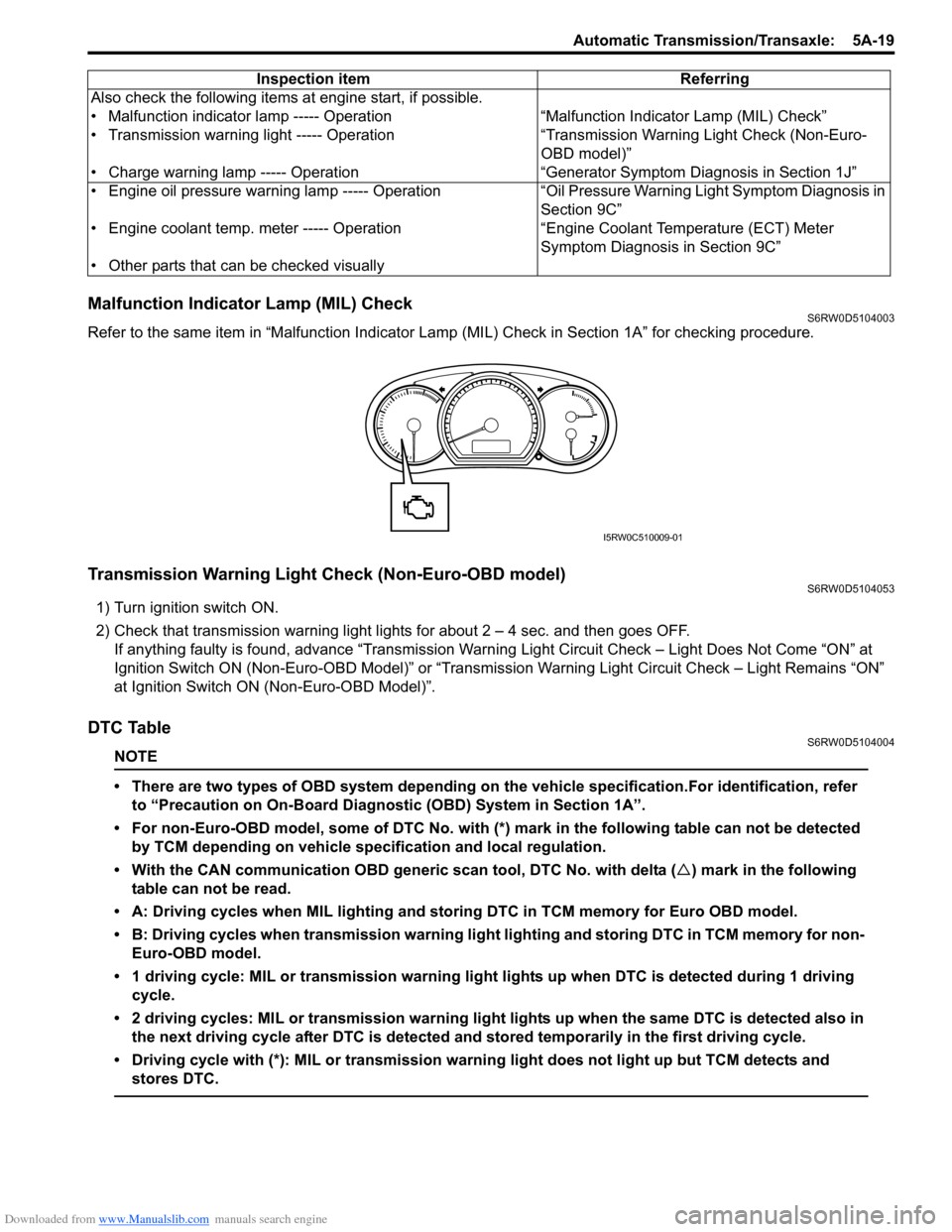
Malfunction Indicator Lamp (MIL) CheckS6RW0D5104003
Refer to the same item in “Malfunction Indicator Lamp (MIL) Check in Section 1A” for checking procedure.
Transmission Warning Light Check (Non-Euro-OBD model)S6RW0D5104053
1) Turn ignition switch ON.
2) Check that transmission warning light lights for about 2 – 4 sec. and then goes OFF.
If anything faulty is found, advance “Transmission Warning Light Circuit Check – Light Does Not Come “ON” at
Ignition Switch ON (Non-Euro-OBD Model)” or “Transmission Warning Light Circuit Check – Light Remains “ON”
at Ignition Switch ON (Non-Euro-OBD Model)”.
DTC TableS6RW0D5104004
NOTE
• There are two types of OBD system depending on the vehicle specification.For identification, refer
to “Precaution on On-Board Diagnostic (OBD) System in Section 1A”.
• For non-Euro-OBD model, some of DTC No. with (*) mark in the following table can not be detected
by TCM depending on vehicle specification and local regulation.
• With the CAN communication OBD generic scan tool, DTC No. with delta (�U) mark in the following
table can not be read.
• A: Driving cycles when MIL lighting and storing DTC in TCM memory for Euro OBD model.
• B: Driving cycles when transmission warning light lighting and storing DTC in TCM memory for non-
Euro-OBD model.
• 1 driving cycle: MIL or transmission warning light lights up when DTC is detected during 1 driving
cycle.
• 2 driving cycles: MIL or transmission warning light lights up when the same DTC is detected also in
the next driving cycle after DTC is detected and stored temporarily in the first driving cycle.
• Driving cycle with (*): MIL or transmission warning light does not light up but TCM detects and
stores DTC.
Also check the following items at engine start, if possible.
• Malfunction indicator lamp ----- Operation “Malfunction Indicator Lamp (MIL) Check”
• Transmission warning light ----- Operation “Transmission Warning Light Check (Non-Euro-
OBD model)”
• Charge warning lamp ----- Operation “Generator Symptom Diagnosis in Section 1J”
• Engine oil pressure warning lamp ----- Operation “Oil Pressure Warning Light Symptom Diagnosis in
Section 9C”
• Engine coolant temp. meter ----- Operation “Engine Coolant Temperature (ECT) Meter
Symptom Diagnosis in Section 9C”
• Other parts that can be checked visuallyInspection item Referring
I5RW0C510009-01
Page 688 of 1556
Downloaded from www.Manualslib.com manuals search engine 5A-40 Automatic Transmission/Transaxle:
Trouble Diagnosis 3
Off-vehicle repairNon operate TCC (lock-
up) systemMalfunction of TCC solenoid valveInspect. If NG, replace.
Malfunction of shift solenoid valve-A
and/or -BInspect. If NG, replace.
Malfunction of output shaft speed
sensor (VSS)Inspect. If NG, replace.
Malfunction of input shaft speed sensorInspect. If NG, replace.
Malfunction of transmission range
sensorInspect. If NG, replace.
Malfunction of transmission fluid
temperature sensorInspect. If NG, replace.
Malfunction of pressure control solenoid
valveInspect. If NG, replace valve body assembly.
Malfunction of Accelerator pedal
position (APP) sensorInspect referring to “Accelerator Pedal Position
(APP) Sensor Assembly On-Vehicle Inspection
in Section 1C”. If NG, replace.
Malfunction of engine coolant
temperature sensorInspect referring to “Engine Coolant
Temperature (ECT) Sensor Inspection in
Section 1C”. If NG, replace.
Malfunction of brake light switchInspect referring to “Brake Light Switch
Inspection in Section 9B”. If NG, replace.
Faulty valve body componentReplace valve body assembly.
Excessive “N”
→ “D” or
“N”
→ “R” time lagMalfunction of transmission fluid
temperature sensorInspect. If NG, replace.
Pressure control solenoid valve circuit
faultyInspect. If NG, replace valve body assembly.
Clogged oil strainerReplace.
Faulty valve body componentReplace valve body assembly. Condition Possible cause Correction / Reference Item
Condition Possible cause Correction / Reference Item
Unable to run in all rangeFaulty oil pumpInspect. If NG, replace.
Seized or broken planetary gearInspect. If NG, replace.
Faulty one-way No.2 clutchInspect. If NG, replace.
Damaged drive plateInspect. If NG, replace.
Faulty forward clutchInspect. If NG, replace.
Faulty reverse clutchInspect. If NG, replace.
Faulty 1st and reverse brakeInspect. If NG, replace.
Faulty torque converterReplace.
Excessive “N”
→ “D” shift
shockFaulty forward clutchInspect. If NG, replace.
Excessive “N”
→ “R” shift
shockFaulty reverse clutchInspect. If NG, replace.
Faulty 1st and reverse brakeInspect. If NG, replace.
Poor 1
→ 2 shift,
excessive shock or
slippageFaulty 2nd brakeInspect. If NG, replace.
Faulty one-way No.1 clutchInspect. If NG, replace.
Poor 2
→ 3 shift,
excessive shock or
slippageFaulty direct clutchInspect. If NG, replace.
Poor 3
↔ O/D shift,
excessive shock or
slippageFaulty forward clutchInspect. If NG, replace.
Faulty O/D and 2nd coast brakeInspect. If NG, replace.
Poor 3
→ 2 shift,
excessive shock or
slippageFaulty direct clutchInspect. If NG, replace.
Faulty one-way No.1 clutchInspect. If NG, replace.
Poor 2
→ 1 shift,
excessive shock or
slippageFaulty 2nd brakeInspect. If NG, replace.
Faulty one-way No.2 clutchInspect. If NG, replace.
Page 739 of 1556

Downloaded from www.Manualslib.com manuals search engine Automatic Transmission/Transaxle: 5A-91
Input Shaft Speed Sensor Removal and
Installation
S6RW0D5106012
Removal
1) Disconnect negative cable at battery.
2) Disconnect input shaft speed sensor connector (2).
3) Remove input shaft speed sensor (1) by removing its
bolt.
Installation
1) Apply A/T fluid to input shaft speed sensor O-ring.
2) Install input shaft speed sensor (1) to A/T case and
tighten bolt to specified torque.
Tightening torque
Input shaft speed sensor bolt (a): 5.5 N·m (0.55
kgf-m, 4.0 lb-ft)
3) Connect input shaft speed sensor connector (2) to
input shaft speed sensor (1).
4) Connect negative cable to battery.
Input Shaft Speed Sensor InspectionS6RW0D5106013
1) Disconnect negative cable at battery.
2) Disconnect input shaft speed sensor connector (2).
3) Check resistance between input shaft speed sensor
(1) terminals.
Input shaft speed sensor resistance
Standard: 560 – 680 Ω at 20 °C (68 °F)
Transmission Fluid Temperature Sensor
Removal and Installation
S6RW0D5106014
Removal
1) Disconnect negative cable at battery.
2) Lift up vehicle.
3) Remove left side engine under cover.
4) With engine is cool, remove drain plug and drain A/T
fluid.
5) Install drain plug. Refer to “A/T Fluid Change”.
6) Remove A/T oil pan.
7) Remove oil strainer assembly.
8) Remove valve body assembly referring to
“Automatic Transaxle Unit Disassembly”.
CAUTION!
When pulling valve body harness out of
transaxle case, take care not to damage
transmission fluid temperature sensor at
narrow exit of case.
Careless sensor treatment might cause
sensor malfunction.
9) Remove valve body harness (1).
12
I5RW0C510034-01
12
(a)I5RW0C510035-01
12I5RW0C510036-01
I2RH0B510050-01
Page 740 of 1556

Downloaded from www.Manualslib.com manuals search engine 5A-92 Automatic Transmission/Transaxle:
Installation
Reverse removal procedure to install valve body
harness and valve body assembly noting the following
points.
• For details of valve body assembly and their
connectors installation, refer to “Automatic Transaxle
Unit Assembly”.
• For details of A/T oil pan installation, refer to
“Automatic Transaxle Unit Assembly”. Use new oil
pan gasket.
• Tighten valve body harness connector bolt to
specified torque.
Tightening torque
Valve body harness connector bolt (a): 5.5 N·m (
0.55 kgf-m, 4.0 lb-ft)
• Pour A/T fluid and check fluid level according to
procedure described in “A/T Fluid Change”.
• Check for fluid leakage after warming up A/T.Transmission Fluid Temperature Sensor
Inspection
S6RW0D5106015
Warm up transmission fluid temperature sensor (2).
Check resistance between terminals of valve body
harness connector (1). Thus make sure its resistance
decrease as its temperature increase.
Transmission fluid temperature sensor resistance
10 °C (50 °F): 5.8 – 7.1 kΩ
11 0 °C (230 °F): 231 – 263 Ω
145 °C (293 °F): 105 – 117 Ω
Solenoid Valves (Shift Solenoid Valves and
Timing Solenoid Valve) Removal and
Installation
S6RW0D5106061
Removal
1) Disconnect negative cable at battery.
2) Lift up vehicle.
3) Remove left side engine under cover.
4) Remove drain plug and drain A/T fluid.
5) Install drain plug.
Tightening torque
A/T fluid drain plug: 17 N·m (1.7 kgf-m, 12.5 lb-ft)
6) Remove A/T oil pan (1) and oil pan gasket (2).
I2RH0B510051-01
I2RH0B510052-01
Page 742 of 1556
Downloaded from www.Manualslib.com manuals search engine 5A-94 Automatic Transmission/Transaxle:
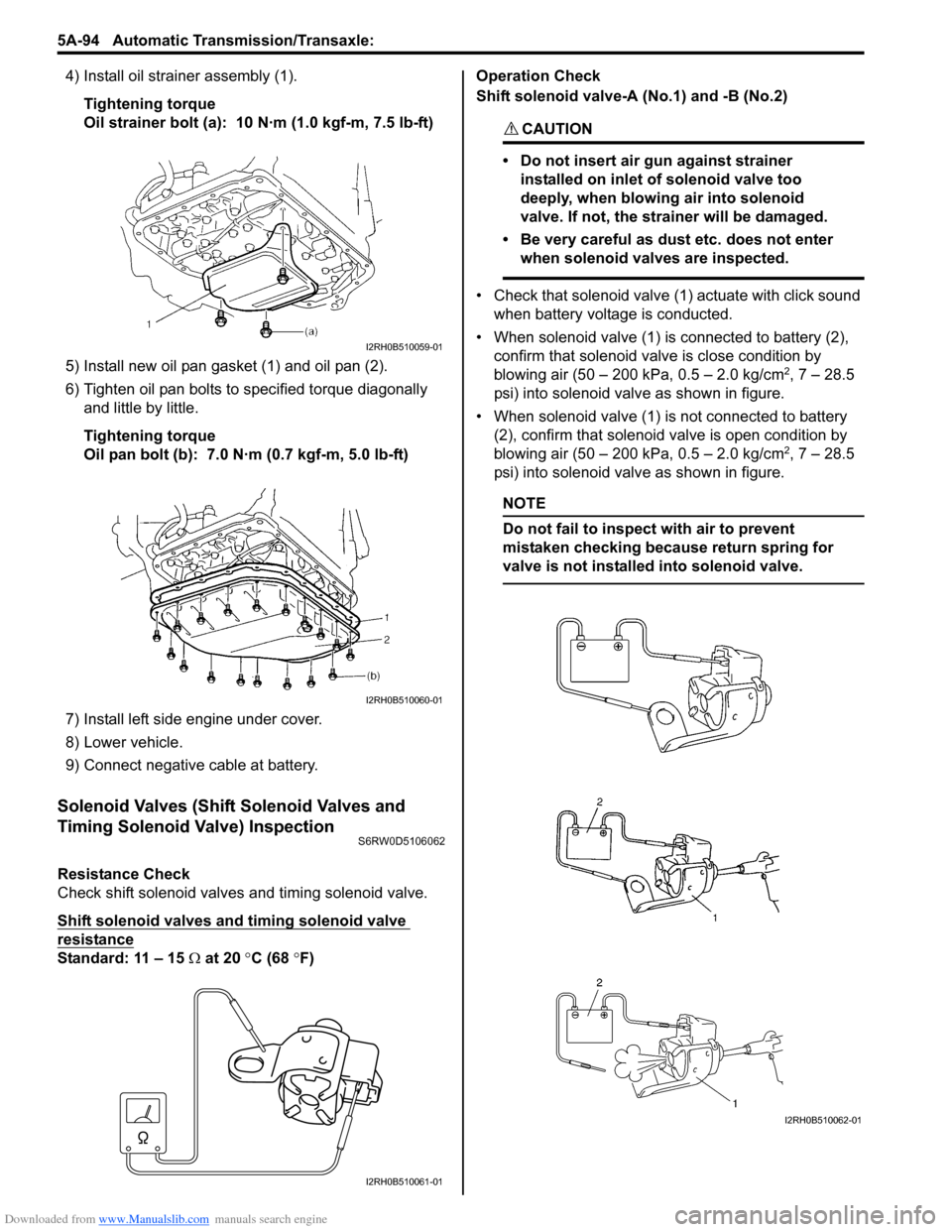
4) Install oil strainer assembly (1).
Tightening torque
Oil strainer bolt (a): 10 N·m (1.0 kgf-m, 7.5 lb-ft)
5) Install new oil pan gasket (1) and oil pan (2).
6) Tighten oil pan bolts to specified torque diagonally
and little by little.
Tightening torque
Oil pan bolt (b): 7.0 N·m (0.7 kgf-m, 5.0 lb-ft)
7) Install left side engine under cover.
8) Lower vehicle.
9) Connect negative cable at battery.
Solenoid Valves (Shift Solenoid Valves and
Timing Solenoid Valve) Inspection
S6RW0D5106062
Resistance Check
Check shift solenoid valves and timing solenoid valve.
Shift solenoid valves and timing solenoid valve
resistance
Standard: 11 – 15 Ω at 20 °C (68 °F)Operation Check
Shift solenoid valve-A (No.1) and -B (No.2)
CAUTION!
• Do not insert air gun against strainer
installed on inlet of solenoid valve too
deeply, when blowing air into solenoid
valve. If not, the strainer will be damaged.
• Be very careful as dust etc. does not enter
when solenoid valves are inspected.
• Check that solenoid valve (1) actuate with click sound
when battery voltage is conducted.
• When solenoid valve (1) is connected to battery (2),
confirm that solenoid valve is close condition by
blowing air (50 – 200 kPa, 0.5 – 2.0 kg/cm
2, 7 – 28.5
psi) into solenoid valve as shown in figure.
• When solenoid valve (1) is not connected to battery
(2), confirm that solenoid valve is open condition by
blowing air (50 – 200 kPa, 0.5 – 2.0 kg/cm
2, 7 – 28.5
psi) into solenoid valve as shown in figure.
NOTE
Do not fail to inspect with air to prevent
mistaken checking because return spring for
valve is not installed into solenoid valve.
I2RH0B510059-01
I2RH0B510060-01
I2RH0B510061-01
I2RH0B510062-01
Page 744 of 1556
Downloaded from www.Manualslib.com manuals search engine 5A-96 Automatic Transmission/Transaxle:
10) Remove valve body assembly referring to
“Automatic Transaxle Unit Disassembly”.
11) Remove pressure control solenoid valve and TCC
pressure control solenoid valve referring to “Valve
Body Assembly Disassembly and Reassembly”.
Installation
Reverse removal procedure to install pressure control
solenoid valve and valve body assembly noting the
following points.
• For detail of pressure control solenoid valve and TCC
pressure control solenoid valve installation, refer to
“Valve Body Assembly Disassembly and
Reassembly”.
• For detail of valve body assembly installation, refer to
“Automatic Transaxle Unit Assembly”.
• For detail of installing wire harness for solenoid valves
and sensor, refer to “Automatic Transaxle Unit
Assembly”. Use new O-rings.
• For detail of A/T oil pan and oil strainer assembly
installation, refer to “Automatic Transaxle Unit
Assembly”. Use new oil pan gasket.
• Pour A/T fluid and check fluid level according to
procedure described in “A/T Fluid Change”.
• Check for fluid leakage after warming up A/T.
Pressure Control Solenoid Valves InspectionS6RW0D5106020
CAUTION!
• Be very careful as dust etc. does enter
when pressure control solenoid valves are
inspected.
Resistance Check
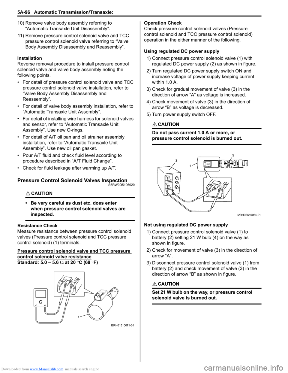
Measure resistance between pressure control solenoid
valves (Pressure control solenoid and TCC pressure
control solenoid) (1) terminals.
Pressure control solenoid valve and TCC pressure
control solenoid valve resistance
Standard: 5.0 – 5.6 Ω at 20 °C (68 °F)Operation Check
Check pressure control solenoid valves (Pressure
control solenoid and TCC pressure control solenoid)
operation in the either manner of the following.
Using regulated DC power supply
1) Connect pressure control solenoid valve (1) with
regulated DC power supply (2) as shown in figure.
2) Turn regulated DC power supply switch ON and
increase voltage of power supply keeping current
within 1.0 A.
3) Check for gradual movement of valve (3) in the
direction of arrow “A” as voltage is increased.
4) Check movement of valve (3) in the direction of
arrow “B” as voltage is decreased.
5) Turn power supply switch OFF.
CAUTION!
Do not pass current 1.0 A or more, or
pressure control solenoid is burned out.
Not using regulated DC power supply
1) Connect pressure control solenoid valve (1) to
battery (2) setting 21 W bulb (4) on the way as
shown in figure.
2) Check for movement of valve (3) in the direction of
arrow “A”.
3) Disconnect pressure control solenoid valve (1) from
battery (2) and check movement of valve (3) in the
direction of arrow “B” as shown in figure.
CAUTION!
Set 21 W bulb on the way, or pressure control
solenoid valve is burned out.
1
I2RH01510071-01
I2RH0B510064-01
Page 765 of 1556

Downloaded from www.Manualslib.com manuals search engine Automatic Transmission/Transaxle: 5A-117
Reassembly
1) Install new oil pump body oil seal (1).
Use special tool and hammer to install it, and then
apply grease to its lip portion.
Special tool
(A): 09913–85210
“A”: Grease 99000–25030 (SUZUKI Super
Grease C)
2) Install driven gear and drive gear to oil pump body
after applying A/T fluid.
3) Install stator shaft assembly to oil pump body and
tighten 8 pump subassembly bolts (1) to
specification.
Tightening torque
Oil pump subassembly bolt (a): 10 N·m (1.0 kgf-
m, 7.5 lb-ft)
4) After applying A/T fluid to new O-ring, install it to oil
pump body.
5) Check drive gear for smooth rotation by using torque
converter (1).Oil Pump Assembly InspectionS6RW0D5106034
1) Check body clearance of driven gear (1).
Push driven gear to one side of oil pump body (2).
Using a feeler gauge, measure clearance between
driven gear and body. If clearance exceeds its
standard value, replace oil pump assembly.
Clearance between oil pump driven gear and oil
pump body
Standard: 0.10 – 0.17 mm (0.0039 – 0.0067 in.)
2) Check tip clearance of both drive and driven gears.
Using a feeler gauge, measure clearance between
drive and driven gear tips. If clearance exceeds its
standard value, replace oil pump assembly.
Tip clearance between oil pump drive gear and
oil pump driven gear
Standard: 0.07 – 0.15 mm (0.0028 – 0.0059 in.)
2. Oil pump body
I2RH0B510151-01
1, (a)
I4RS0A510042-01
1
I4RS0A510043-01
I2RH0B510154-01
I2RH0B510155-01
Page 789 of 1556
Downloaded from www.Manualslib.com manuals search engine Automatic Transmission/Transaxle: 5A-141
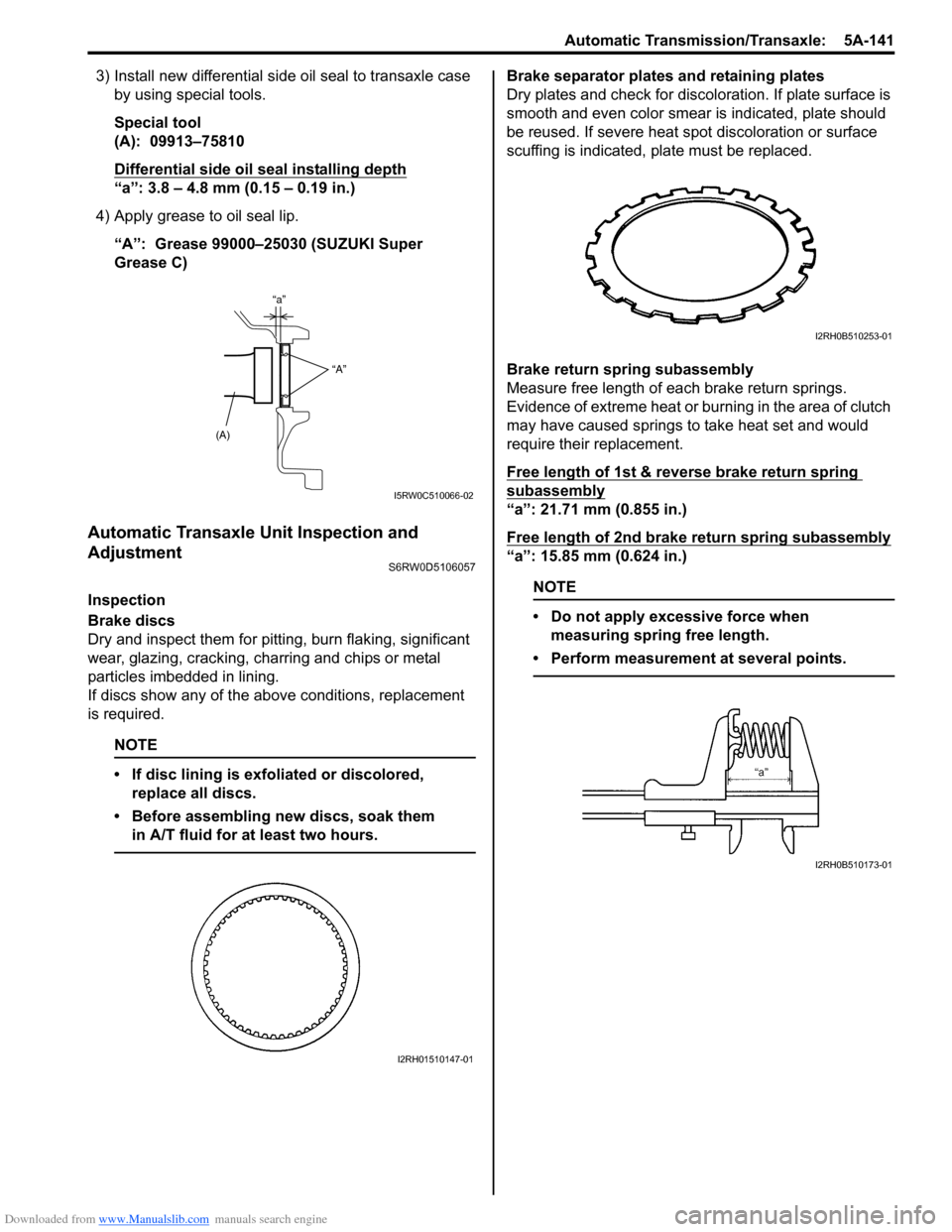
3) Install new differential side oil seal to transaxle case
by using special tools.
Special tool
(A): 09913–75810
Differential side oil seal installing depth
“a”: 3.8 – 4.8 mm (0.15 – 0.19 in.)
4) Apply grease to oil seal lip.
“A”: Grease 99000–25030 (SUZUKI Super
Grease C)
Automatic Transaxle Unit Inspection and
Adjustment
S6RW0D5106057
Inspection
Brake discs
Dry and inspect them for pitting, burn flaking, significant
wear, glazing, cracking, charring and chips or metal
particles imbedded in lining.
If discs show any of the above conditions, replacement
is required.
NOTE
• If disc lining is exfoliated or discolored,
replace all discs.
• Before assembling new discs, soak them
in A/T fluid for at least two hours.
Brake separator plates and retaining plates
Dry plates and check for discoloration. If plate surface is
smooth and even color smear is indicated, plate should
be reused. If severe heat spot discoloration or surface
scuffing is indicated, plate must be replaced.
Brake return spring subassembly
Measure free length of each brake return springs.
Evidence of extreme heat or burning in the area of clutch
may have caused springs to take heat set and would
require their replacement.
Free length of 1st & reverse brake return spring
subassembly
“a”: 21.71 mm (0.855 in.)
Free length of 2nd brake return spring subassembly
“a”: 15.85 mm (0.624 in.)
NOTE
• Do not apply excessive force when
measuring spring free length.
• Perform measurement at several points.
(A)“a”
“A”
I5RW0C510066-02
I2RH01510147-01
I2RH0B510253-01
I2RH0B510173-01
Page 822 of 1556

Downloaded from www.Manualslib.com manuals search engine 5B-10 Manual Transmission/Transaxle:
3) Apply grease to pin (5) of gear shift control lever, and
then install adjuster (1) into pin of gear shift control
lever securely.
“A”: Grease 99000–25011 (SUZUKI Super
Grease A)
4) Push cable end holder (2) in the direction of A.
NOTE
At this time, do not apply force in the cable
operation direction B to adjuster.
5) Slide lock plate (3) in the direction of C, until it gets
over the claw (4) of cable end holder.
Back Up Light Switch Removal and InstallationS6RW0D5206007
Removal
1) Remove battery and tray with ECM.
2) Disconnect back up light switch coupler (1).
3) Remove back up light switch.
Installation
1) Apply oil to new O-ring (1) and tighten back up light
switch (2) to specified torque.
Tightening torque
Back up light switch (a): 23 N·m (2.3 kgf-m, 17.0
lb-ft)
2) Connect back up light switch coupler.
3) Install battery and tray with ECM.
Back Up Light Switch InspectionS6RW0D5206008
Check back up light switch for function using ohmmeter.
Switch ON (Push): Continuity
Switch OFF (Release): No continuity
3
3
41
2
A C
1
B
5, “A”
I4RS0A520005-01
2. Gear shift and select shaft assembly
2
1I5RW0A520009-01
1 2, (a)
I3RH0A520006-01
I5RW0A520050-01