ignition timing check SUZUKI SX4 2006 1.G Service User Guide
[x] Cancel search | Manufacturer: SUZUKI, Model Year: 2006, Model line: SX4, Model: SUZUKI SX4 2006 1.GPages: 1556, PDF Size: 37.31 MB
Page 162 of 1556
Downloaded from www.Manualslib.com manuals search engine 1A-112 Engine General Information and Diagnosis:
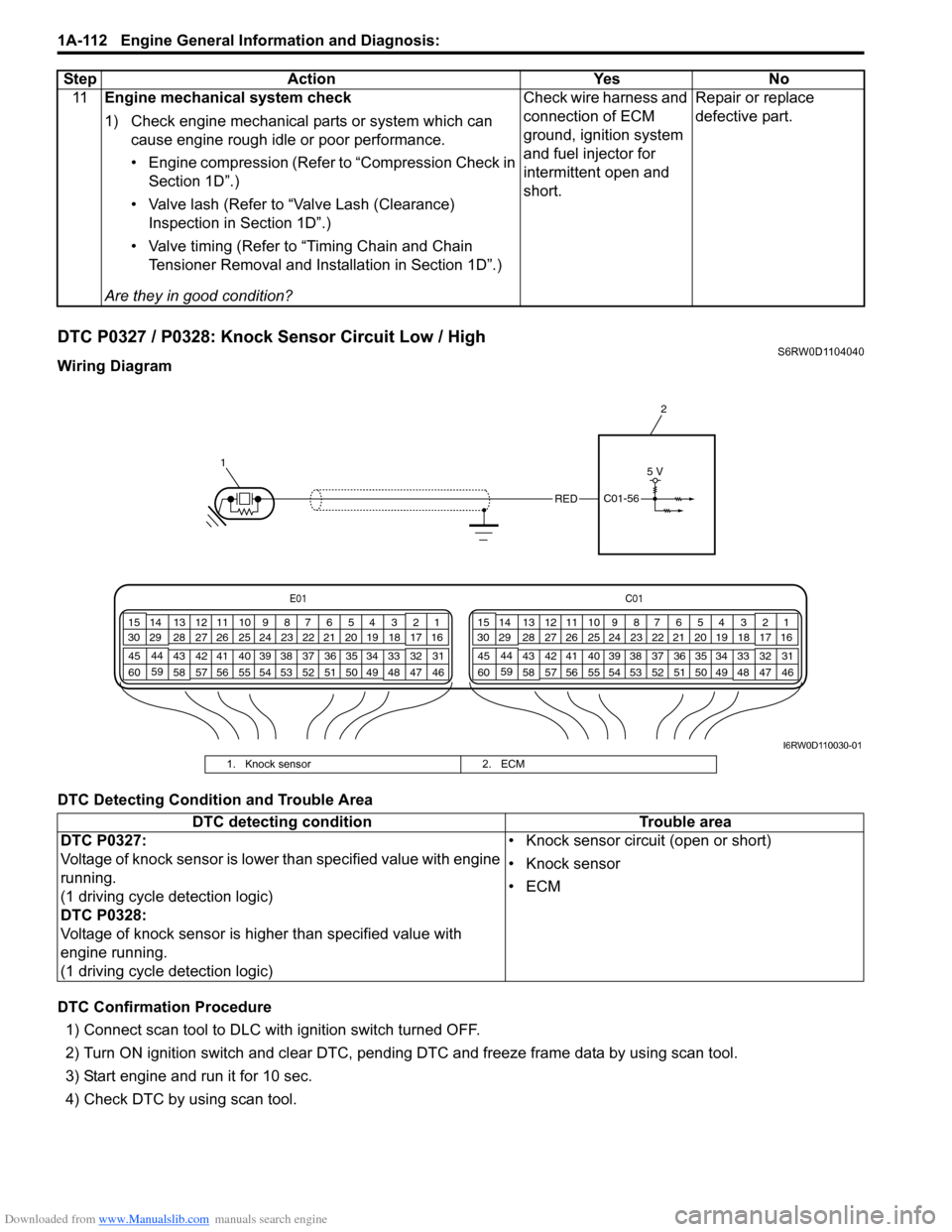
DTC P0327 / P0328: Knock Sensor Circuit Low / HighS6RW0D1104040
Wiring Diagram
DTC Detecting Condition and Trouble Area
DTC Confirmation Procedure
1) Connect scan tool to DLC with ignition switch turned OFF.
2) Turn ON ignition switch and clear DTC, pending DTC and freeze frame data by using scan tool.
3) Start engine and run it for 10 sec.
4) Check DTC by using scan tool.11Engine mechanical system check
1) Check engine mechanical parts or system which can
cause engine rough idle or poor performance.
• Engine compression (Refer to “Compression Check in
Section 1D”.)
• Valve lash (Refer to “Valve Lash (Clearance)
Inspection in Section 1D”.)
• Valve timing (Refer to “Timing Chain and Chain
Tensioner Removal and Installation in Section 1D”.)
Are they in good condition?Check wire harness and
connection of ECM
ground, ignition system
and fuel injector for
intermittent open and
short.Repair or replace
defective part. Step Action Yes No
E01C01
3 4
18 19 5 6 7 10 11
17 20
47 46 49 50 51 21 22
5216 259
24 14
29
55 57 54 53 59
60 582
26 27 28 15
30
56 4832 31 34 35 36 37 40 42 39 38 44
45 43 41 331 12 13
238 3 4
18 19 5 6 7 10 11
17 20
47 46 49 50 51 21 22
5216 259
24 14
29
55 57 54 53 59
60 582
26 27 28 15
30
56 4832 31 34 35 36 37 40 42 39 38 44
45 43 41 331 12 13
238
12
REDC01-56
5 V
I6RW0D110030-01
1. Knock sensor 2. ECM
DTC detecting condition Trouble area
DTC P0327:
Voltage of knock sensor is lower than specified value with engine
running.
(1 driving cycle detection logic)
DTC P0328:
Voltage of knock sensor is higher than specified value with
engine running.
(1 driving cycle detection logic)• Knock sensor circuit (open or short)
• Knock sensor
•ECM
Page 167 of 1556
Downloaded from www.Manualslib.com manuals search engine Engine General Information and Diagnosis: 1A-117
System Description
The CMP sensor located on the transmission side of cylinder head (VVT model) or timing chain cover (non-VVT
model) consists of the signal generator (magnetic sensor) and signal rotor (intake camshaft portion (VVT model) or
exhaust camshaft timing sprocket (non-VVT model)).
The signal generator generates reference signal through slits in the slit plate which turns together with the camshaft.
Reference signal
The CMP sensor generates 6 pulses of signals each of which has a different waveform length while the camshaft
makes one full rotation. Refer to “Inspection of ECM and Its Circuits”.
Based on these signals, ECM judges which cylinder piston is in the compression stroke and the engine speed.
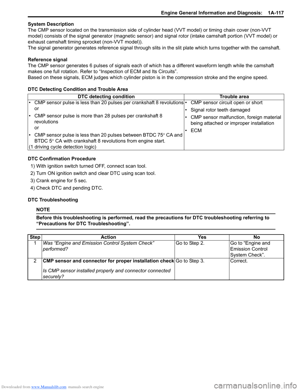
DTC Detecting Condition and Trouble Area
DTC Confirmation Procedure
1) With ignition switch turned OFF, connect scan tool.
2) Turn ON ignition switch and clear DTC using scan tool.
3) Crank engine for 5 sec.
4) Check DTC and pending DTC.
DTC Troubleshooting
NOTE
Before this troubleshooting is performed, read the precautions for DTC troubleshooting referring to
“Precautions for DTC Troubleshooting”.
DTC detecting condition Trouble area
• CMP sensor pulse is less than 20 pulses per crankshaft 8 revolutions
or
• CMP sensor pulse is more than 28 pulses per crankshaft 8
revolutions
or
• CMP sensor pulse is less than 20 pulses between BTDC 75° CA and
BTDC 5° CA with crankshaft 8 revolutions from engine start.
(1 driving cycle detection logic)• CMP sensor circuit open or short
• Signal rotor teeth damaged
• CMP sensor malfunction, foreign material
being attached or improper installation
•ECM
Step Action Yes No
1Was “Engine and Emission Control System Check”
performed?Go to Step 2. Go to “Engine and
Emission Control
System Check”.
2CMP sensor and connector for proper installation check
Is CMP sensor installed properly and connector connected
securely?Go to Step 3. Correct.
Page 262 of 1556
Downloaded from www.Manualslib.com manuals search engine 1A-212 Engine General Information and Diagnosis:
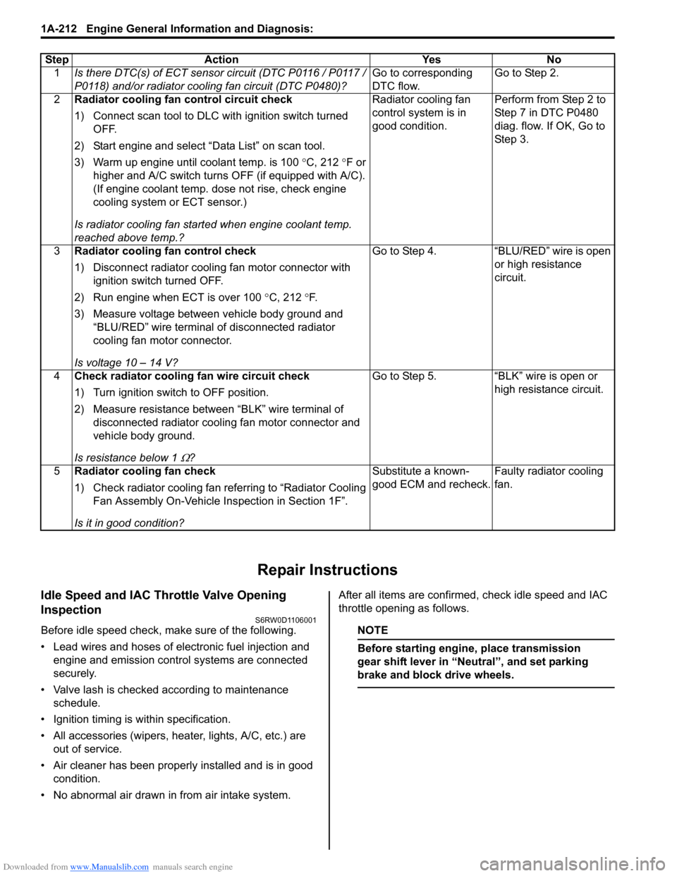
Repair Instructions
Idle Speed and IAC Throttle Valve Opening
Inspection
S6RW0D1106001
Before idle speed check, make sure of the following.
• Lead wires and hoses of electronic fuel injection and
engine and emission control systems are connected
securely.
• Valve lash is checked according to maintenance
schedule.
• Ignition timing is within specification.
• All accessories (wipers, heater, lights, A/C, etc.) are
out of service.
• Air cleaner has been properly installed and is in good
condition.
• No abnormal air drawn in from air intake system.After all items are confirmed, check idle speed and IAC
throttle opening as follows.NOTE
Before starting engine, place transmission
gear shift lever in “Neutral”, and set parking
brake and block drive wheels.
Step Action Yes No
1Is there DTC(s) of ECT sensor circuit (DTC P0116 / P0117 /
P0118) and/or radiator cooling fan circuit (DTC P0480)?Go to corresponding
DTC flow.Go to Step 2.
2Radiator cooling fan control circuit check
1) Connect scan tool to DLC with ignition switch turned
OFF.
2) Start engine and select “Data List” on scan tool.
3) Warm up engine until coolant temp. is 100 °C, 212 °F or
higher and A/C switch turns OFF (if equipped with A/C).
(If engine coolant temp. dose not rise, check engine
cooling system or ECT sensor.)
Is radiator cooling fan started when engine coolant temp.
reached above temp.?Radiator cooling fan
control system is in
good condition.Perform from Step 2 to
Step 7 in DTC P0480
diag. flow. If OK, Go to
Ste p 3.
3Radiator cooling fan control check
1) Disconnect radiator cooling fan motor connector with
ignition switch turned OFF.
2) Run engine when ECT is over 100 °C, 212 °F.
3) Measure voltage between vehicle body ground and
“BLU/RED” wire terminal of disconnected radiator
cooling fan motor connector.
Is voltage 10 – 14 V?Go to Step 4. “BLU/RED” wire is open
or high resistance
circuit.
4Check radiator cooling fan wire circuit check
1) Turn ignition switch to OFF position.
2) Measure resistance between “BLK” wire terminal of
disconnected radiator cooling fan motor connector and
vehicle body ground.
Is resistance below 1
Ω?Go to Step 5. “BLK” wire is open or
high resistance circuit.
5Radiator cooling fan check
1) Check radiator cooling fan referring to “Radiator Cooling
Fan Assembly On-Vehicle Inspection in Section 1F”.
Is it in good condition?Substitute a known-
good ECM and recheck.Faulty radiator cooling
fan.
Page 287 of 1556
Downloaded from www.Manualslib.com manuals search engine Engine Mechanical: 1D-5
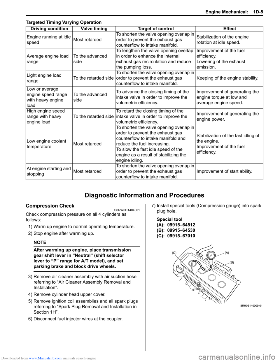
Targeted Timing Varying Operation
Diagnostic Information and Procedures
Compression CheckS6RW0D1404001
Check compression pressure on all 4 cylinders as
follows:
1) Warm up engine to normal operating temperature.
2) Stop engine after warming up.
NOTE
After warming up engine, place transmission
gear shift lever in “Neutral” (shift selector
lever to “P” range for A/T model), and set
parking brake and block drive wheels.
3) Remove air cleaner assembly with air suction hose
referring to “Air Cleaner Assembly Removal and
Installation”.
4) Remove cylinder head upper cover.
5) Remove ignition coil assemblies and all spark plugs
referring to “Spark Plug Removal and Installation in
Section 1H”.
6) Disconnect fuel injector wires at the coupler.7) Install special tools (Compression gauge) into spark
plug hole.
Special tool
(A): 09915–64512
(B): 09915–64530
(C): 09915–67010 Driving condition Valve timing Target of control Effect
Engine running at idle
speedMost retardedTo shorten the valve opening overlap in
order to prevent the exhaust gas
counterflow to intake manifold.Stabilization of the engine
rotation at idle speed.
Average engine load
rangeTo the advanced
sideTo lengthen the valve opening overlap
in order to enhance the internal
exhaust gas recirculation and reduce
the pumping loss.Improvement of the fuel
efficiency.
Lowering of the exhaust
emission.
Light engine load
rangeTo the retarded sideTo shorten the valve opening overlap in
order to prevent the exhaust gas
counterflow to intake manifold.Keeping of the engine stability.
Low or average
engine speed range
with heavy engine
loadTo the advanced
sideTo advance the closing timing of the
intake valve in order to improve the
volumetric efficiency.Improvement of generating the
engine torque at low and
average engine speed.
High engine speed
range with heavy
engine loadTo the retarded sideTo retard the closing timing of the
intake valve in order to improve the
volumetric efficiency.Improvement of generating the
engine power.
Low engine coolant
temperatureMost retardedTo shorten the valve opening overlap in
order to prevent the exhaust gas
counterflow to intake manifold and
reduce the fuel increasing.
To slow the fast idle speed of the
engine as a result of stabilizing the
engine idling.Stabilization of the fast idling of
the engine.
Improvement of the fuel
efficiency.
At engine starting and
stoppingMost retardedTo shorten the valve opening overlap in
order to prevent the exhaust gas
counterflow to intake manifold.Improvement of start ability.
(A)
(C)
(B)
I3RH0B140009-01
Page 399 of 1556
Downloaded from www.Manualslib.com manuals search engine Ignition System: 1H-4
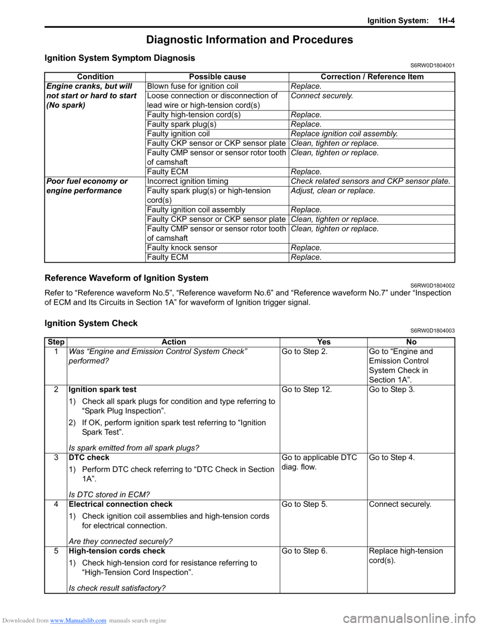
Diagnostic Information and Procedures
Ignition System Symptom DiagnosisS6RW0D1804001
Reference Waveform of Ignition SystemS6RW0D1804002
Refer to “Reference waveform No.5”, “Reference waveform No.6” and “Reference waveform No.7” under “Inspection
of ECM and Its Circuits in Section 1A” for waveform of Ignition trigger signal.
Ignition System CheckS6RW0D1804003
Condition Possible cause Correction / Reference Item
Engine cranks, but will
not start or hard to start
(No spark)Blown fuse for ignition coilReplace.
Loose connection or disconnection of
lead wire or high-tension cord(s)Connect securely.
Faulty high-tension cord(s)Replace.
Faulty spark plug(s)Replace.
Faulty ignition coilReplace ignition coil assembly.
Faulty CKP sensor or CKP sensor plateClean, tighten or replace.
Faulty CMP sensor or sensor rotor tooth
of camshaftClean, tighten or replace.
Faulty ECMReplace.
Poor fuel economy or
engine performanceIncorrect ignition timingCheck related sensors and CKP sensor plate.
Faulty spark plug(s) or high-tension
cord(s)Adjust, clean or replace.
Faulty ignition coil assemblyReplace.
Faulty CKP sensor or CKP sensor plateClean, tighten or replace.
Faulty CMP sensor or sensor rotor tooth
of camshaftClean, tighten or replace.
Faulty knock sensorReplace.
Faulty ECMReplace.
Step Action Yes No
1Was “Engine and Emission Control System Check”
performed?Go to Step 2. Go to “Engine and
Emission Control
System Check in
Section 1A”.
2Ignition spark test
1) Check all spark plugs for condition and type referring to
“Spark Plug Inspection”.
2) If OK, perform ignition spark test referring to “Ignition
Spar k Tes t”.
Is spark emitted from all spark plugs?Go to Step 12. Go to Step 3.
3DTC check
1) Perform DTC check referring to “DTC Check in Section
1A”.
Is DTC stored in ECM?Go to applicable DTC
diag. flow.Go to Step 4.
4Electrical connection check
1) Check ignition coil assemblies and high-tension cords
for electrical connection.
Are they connected securely?Go to Step 5. Connect securely.
5High-tension cords check
1) Check high-tension cord for resistance referring to
“High-Tension Cord Inspection”.
Is check result satisfactory?Go to Step 6. Replace high-tension
cord(s).
Page 400 of 1556
Downloaded from www.Manualslib.com manuals search engine 1H-5 Ignition System:
6Ignition coil assembly power supply and ground circuit
check
1) Check ignition coil assembly power supply and ground
circuits for open and short.
Are circuits in good condition?Go to Step 7. Repair or replace.
7Ignition coil assembly check
1) Check ignition coil for resistance referring to “Ignition
Coil Assembly (Including Ignitor) Inspection”.
Is check result satisfactory?Go to Step 8. Replace ignition coil
assembly.
8CKP sensor check
1) Check CKP sensor referring to “Crankshaft Position
(CKP) Sensor Inspection in Section 1C”.
Is check result satisfactory?Go to Step 9. Tighten CKP sensor
bolt, replace CKP
sensor or CKP sensor
plate.
9CMP sensor check
1) Check CMP sensor referring to “Camshaft Position
(CMP) Sensor Inspection in Section 1C”.
Is check result satisfactory?Go to Step 10. Tighten CMP sensor
bolt, replace CMP
sensor or intake
camshaft.
10Ignition trigger signal circuit check
1) Check ignition trigger signal wire for open, short and
poor connection.
Is circuit in good condition?Go to Step 11. Repair or replace.
11A known-good ignition coil assembly substitution
1) Substitute a known-good ignition coil assembly and then
repeat Step 2.
Is check result of Step 2 satisfactory?Go to Step 12. Substitute a known-
good ECM and then
repeat Step 2.
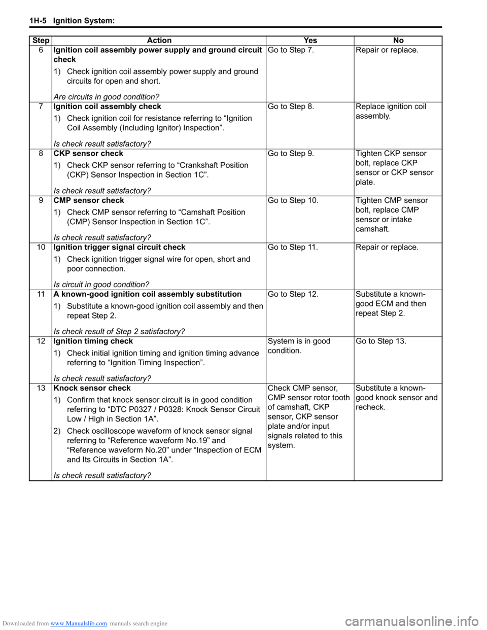
12Ignition timing check
1) Check initial ignition timing and ignition timing advance
referring to “Ignition Timing Inspection”.
Is check result satisfactory?System is in good
condition.Go to Step 13.
13Knock sensor check
1) Confirm that knock sensor circuit is in good condition
referring to “DTC P0327 / P0328: Knock Sensor Circuit
Low / High in Section 1A”.
2) Check oscilloscope waveform of knock sensor signal
referring to “Reference waveform No.19” and
“Reference waveform No.20” under “Inspection of ECM
and Its Circuits in Section 1A”.
Is check result satisfactory?Check CMP sensor,
CMP sensor rotor tooth
of camshaft, CKP
sensor, CKP sensor
plate and/or input
signals related to this
system.Substitute a known-
good knock sensor and
recheck. Step Action Yes No
Page 403 of 1556
Downloaded from www.Manualslib.com manuals search engine Ignition System: 1H-8
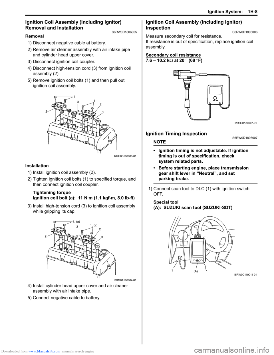
Ignition Coil Assembly (Including Ignitor)
Removal and Installation
S6RW0D1806005
Removal
1) Disconnect negative cable at battery.
2) Remove air cleaner assembly with air intake pipe
and cylinder head upper cover.
3) Disconnect ignition coil coupler.
4) Disconnect high-tension cord (3) from ignition coil
assembly (2).
5) Remove ignition coil bolts (1) and then pull out
ignition coil assembly.
Installation
1) Install ignition coil assembly (2).
2) Tighten ignition coil bolts (1) to specified torque, and
then connect ignition coil coupler.
Tightening torque
Ignition coil bolt (a): 11 N·m (1.1 kgf-m, 8.0 lb-ft)
3) Install high-tension cord (3) to ignition coil assembly
while gripping its cap.
4) Install cylinder head upper cover and air cleaner
assembly with air intake pipe.
5) Connect negative cable to battery.
Ignition Coil Assembly (Including Ignitor)
Inspection
S6RW0D1806006
Measure secondary coil for resistance.
If resistance is out of specification, replace ignition coil
assembly.
Secondary coil resistance
7.6 – 10.2 kΩ at 20 ° (68 °F)
Ignition Timing InspectionS6RW0D1806007
NOTE
• Ignition timing is not adjustable. If ignition
timing is out of specification, check
system related parts.
• Before starting engine, place transmission
gear shift lever in “Neutral”, and set
parking brake.
1) Connect scan tool to DLC (1) with ignition switch
OFF.
Special tool
(A): SUZUKI scan tool (SUZUKI-SDT)
I2RH0B180006-01
I3RM0A180004-01
I2RH0B180007-01
(A) 1I 5 R W 0 C 11 0 0 11 - 0 1
Page 404 of 1556
Downloaded from www.Manualslib.com manuals search engine 1H-9 Ignition System:
2) Start engine and warm it up to normal operating
temperature.
3) Make sure that all of electrical loads except ignition
are switched off.
4) Check to be sure that idle speed is within
specification.
5) Fix ignition timing by using “Fixed Spark Control” of
“Engine / Active Test” mode on scan tool.
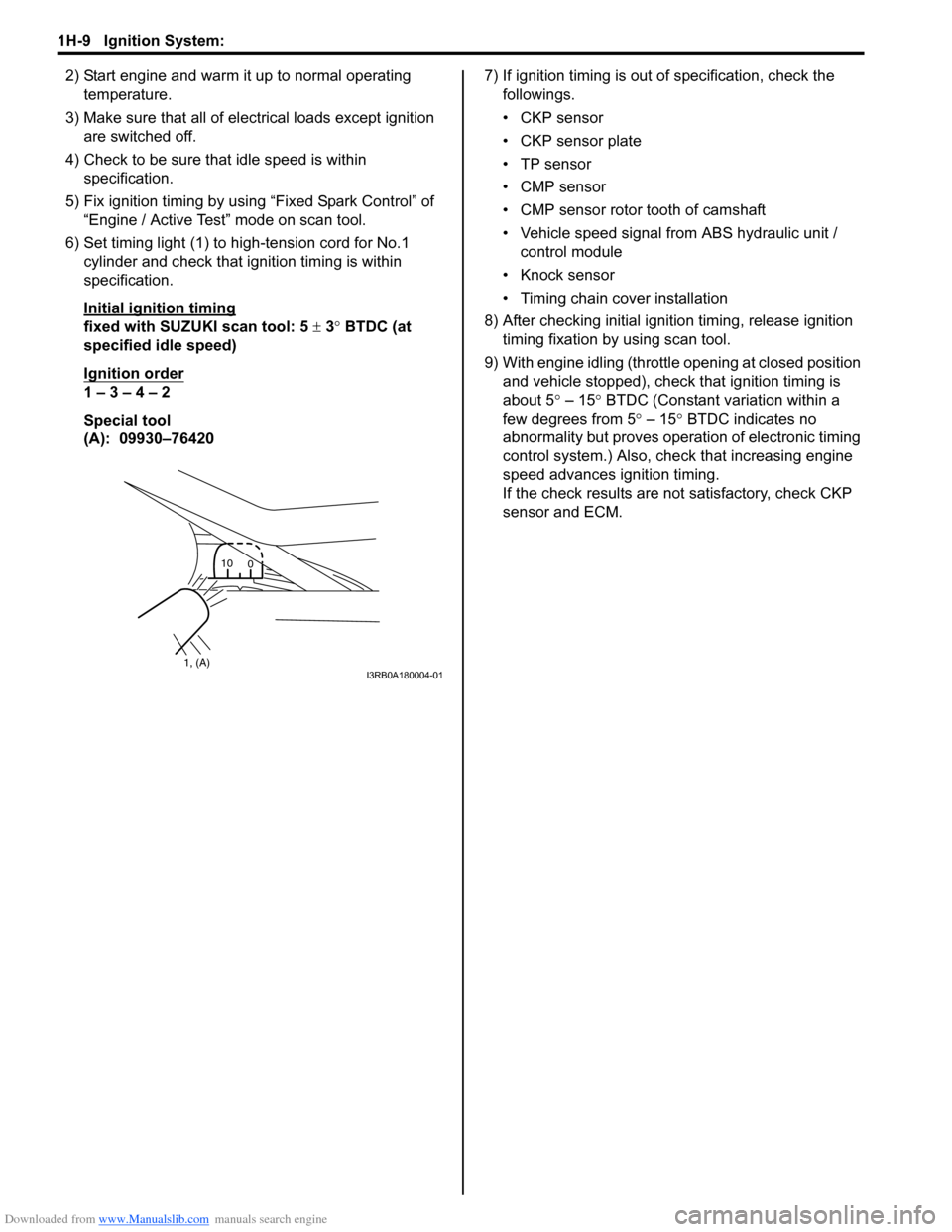
6) Set timing light (1) to high-tension cord for No.1
cylinder and check that ignition timing is within
specification.
Initial ignition timing
fixed with SUZUKI scan tool: 5 ± 3° BTDC (at
specified idle speed)
Ignition order
1 – 3 – 4 – 2
Special tool
(A): 09930–764207) If ignition timing is out of specification, check the
followings.
• CKP sensor
• CKP sensor plate
• TP sensor
• CMP sensor
• CMP sensor rotor tooth of camshaft
• Vehicle speed signal from ABS hydraulic unit /
control module
• Knock sensor
• Timing chain cover installation
8) After checking initial ignition timing, release ignition
timing fixation by using scan tool.
9) With engine idling (throttle opening at closed position
and vehicle stopped), check that ignition timing is
about 5° – 15° BTDC (Constant variation within a
few degrees from 5° – 15° BTDC indicates no
abnormality but proves operation of electronic timing
control system.) Also, check that increasing engine
speed advances ignition timing.
If the check results are not satisfactory, check CKP
sensor and ECM.
1, (A)10
0I3RB0A180004-01
Page 645 of 1556
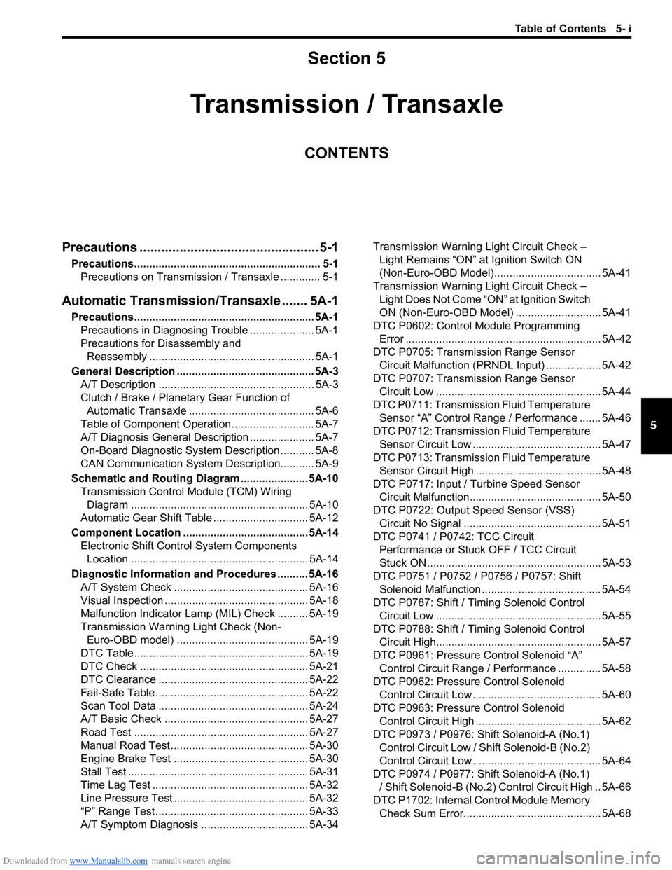
Downloaded from www.Manualslib.com manuals search engine Table of Contents 5- i
5
Section 5
CONTENTS
Transmission / Transaxle
Precautions ................................................. 5-1
Precautions............................................................. 5-1
Precautions on Transmission / Transaxle ............. 5-1
Automatic Transmission/Transaxle ....... 5A-1
Precautions........................................................... 5A-1
Precautions in Diagnosing Trouble ..................... 5A-1
Precautions for Disassembly and
Reassembly ...................................................... 5A-1
General Description ............................................. 5A-3
A/T Description ................................................... 5A-3
Clutch / Brake / Planetary Gear Function of
Automatic Transaxle ......................................... 5A-6
Table of Component Operation ........................... 5A-7
A/T Diagnosis General Description ..................... 5A-7
On-Board Diagnostic System Description ........... 5A-8
CAN Communication System Description........... 5A-9
Schematic and Routing Diagram ...................... 5A-10
Transmission Control Module (TCM) Wiring
Diagram .......................................................... 5A-10
Automatic Gear Shift Table ............................... 5A-12
Component Location ......................................... 5A-14
Electronic Shift Control System Components
Location .......................................................... 5A-14
Diagnostic Information and Procedures .......... 5A-16
A/T System Check ............................................ 5A-16
Visual Inspection ............................................... 5A-18
Malfunction Indicator Lamp (MIL) Check .......... 5A-19
Transmission Warning Light Check (Non-
Euro-OBD model) ........................................... 5A-19
DTC Table ......................................................... 5A-19
DTC Check ....................................................... 5A-21
DTC Clearance ................................................. 5A-22
Fail-Safe Table .................................................. 5A-22
Scan Tool Data ................................................. 5A-24
A/T Basic Check ............................................... 5A-27
Road Test ......................................................... 5A-27
Manual Road Test ............................................. 5A-30
Engine Brake Test ............................................ 5A-30
Stall Test ........................................................... 5A-31
Time Lag Test ................................................... 5A-32
Line Pressure Test ............................................ 5A-32
“P” Range Test.................................................. 5A-33
A/T Symptom Diagnosis ................................... 5A-34Transmission Warning Light Circuit Check –
Light Remains “ON” at Ignition Switch ON
(Non-Euro-OBD Model)................................... 5A-41
Transmission Warning Light Circuit Check –
Light Does Not Come “ON” at Ignition Switch
ON (Non-Euro-OBD Model)............................ 5A-41
DTC P0602: Control Module Programming
Error ................................................................ 5A-42
DTC P0705: Transmission Range Sensor
Circuit Malfunction (PRNDL Input) .................. 5A-42
DTC P0707: Transmission Range Sensor
Circuit Low ...................................................... 5A-44
DTC P0711: Transmission Fluid Temperature
Sensor “A” Control Range / Performance ....... 5A-46
DTC P0712: Transmission Fluid Temperature
Sensor Circuit Low .......................................... 5A-47
DTC P0713: Transmission Fluid Temperature
Sensor Circuit High ......................................... 5A-48
DTC P0717: Input / Turbine Speed Sensor
Circuit Malfunction........................................... 5A-50
DTC P0722: Output Speed Sensor (VSS)
Circuit No Signal ............................................. 5A-51
DTC P0741 / P0742: TCC Circuit
Performance or Stuck OFF / TCC Circuit
Stuck ON ......................................................... 5A-53
DTC P0751 / P0752 / P0756 / P0757: Shift
Solenoid Malfunction ....................................... 5A-54
DTC P0787: Shift / Timing Solenoid Control
Circuit Low ...................................................... 5A-55
DTC P0788: Shift / Timing Solenoid Control
Circuit High...................................................... 5A-57
DTC P0961: Pressure Control Solenoid “A”
Control Circuit Range / Performance .............. 5A-58
DTC P0962: Pressure Control Solenoid
Control Circuit Low .......................................... 5A-60
DTC P0963: Pressure Control Solenoid
Control Circuit High ......................................... 5A-62
DTC P0973 / P0976: Shift Solenoid-A (No.1)
Control Circuit Low / Shift Solenoid-B (No.2)
Control Circuit Low .......................................... 5A-64
DTC P0974 / P0977: Shift Solenoid-A (No.1)
/ Shift Solenoid-B (No.2) Control Circuit High .. 5A-66
DTC P1702: Internal Control Module Memory
Check Sum Error............................................. 5A-68
Page 703 of 1556

Downloaded from www.Manualslib.com manuals search engine Automatic Transmission/Transaxle: 5A-55
DTC Confirmation Procedure
WARNING!
• When performing a road test, select a place where there is no traffic or possibility of a traffic
accident and be very careful during testing to avoid occurrence of an accident.
• Road test should be carried out with 2 persons, a driver and a tester, on a level road.
1) Connect scan tool to DLC with ignition switch OFF, if available.
2) Clear DTC in TCM memory.
3) Start engine and warm it up to normal operating temperature.
4) Shift select lever to “N” and “D” range for 10 seconds.
5) Start vehicle and increase vehicle speed to 65 km/h (40 mile/h) with throttle position 10% or more.
6) Stop vehicle and turn ignition switch OFF.
7) Repeat Step 3) to 5) one time.
8) Stop vehicle and check DTC.
DTC Troubleshooting
DTC P0787: Shift / Timing Solenoid Control Circuit LowS6RW0D5104028
Wiring Diagram
DTC Detecting Condition and Trouble AreaStep Action Yes No
1Was “A/T System Check” performed?Go to Step 2. Go to “A/T System
Check”.
2 1) Check shift solenoid valve-A (No.1) or -B (No.2) for
operation referring to “Solenoid Valves (Shift Solenoid
Valves and Timing Solenoid Valve) Inspection”.
Are they in good condition?Clean fluid passage or
replace valve body
assembly.Replace shift solenoid
valve-A or -B.
12V
C06-14BLU/BLK
31
2
14
C06C07
[A]
I6RW0B510012-01
1. TCM 3. A/T
2. Timing solenoid valve [A]: Terminal arrangement of TCM connector (viewed from harness side)
DTC detecting condition Trouble area
Voltage of timing solenoid valve TCM terminal is low although
TCM is commanding timing solenoid valve to turn ON.• Timing solenoid valve circuit shorted to ground
• Timing solenoid valve malfunction
•TCM