steering wheel SUZUKI SX4 2006 1.G Service User Guide
[x] Cancel search | Manufacturer: SUZUKI, Model Year: 2006, Model line: SX4, Model: SUZUKI SX4 2006 1.GPages: 1556, PDF Size: 37.31 MB
Page 229 of 1556
Downloaded from www.Manualslib.com manuals search engine Engine General Information and Diagnosis: 1A-179
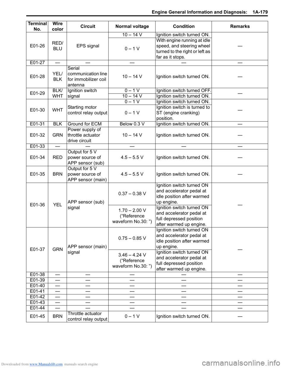
E01-26RED/
BLUEPS signal10 – 14 V Ignition switch turned ON.
—
0 – 1 VWith engine running at idle
speed, and steering wheel
turned to the right or left as
far as it stops.
E01-27 — — — — —
E01-28YEL/
BLKSerial
communication line
for immobilizer coil
antenna10 – 14 V Ignition switch turned ON. —
E01-29BLK/
WHTIgnition switch
signal0 – 1 V Ignition switch turned OFF.
—
10 – 14 V Ignition switch turned ON.
E01-30 WHTStarting motor
control relay output0 – 1 V Ignition switch turned ON.
—
0 – 1 VIgnition switch is turned to
ST (engine cranking)
position.
E01-31 BLK Ground for ECM Below 0.3 V Ignition switch turned ON. —
E01-32 GRNPower supply of
throttle actuator
drive circuit10 – 14 V Ignition switch turned ON. —
E01-33 — — — — —
E01-34 REDOutput for 5 V
power source of
APP sensor (sub)4.5 – 5.5 V Ignition switch turned ON. —
E01-35 BRNOutput for 5 V
power source of
APP sensor (main)4.5 – 5.5 V Ignition switch turned ON. —
E01-36 YELAPP sensor (sub)
signal0.37 – 0.38 VIgnition switch turned ON
and accelerator pedal at
idle position after warmed
up engine.
—
1.70 – 2.00 V
(“Reference
waveform No.30: ”)Ignition switch turned ON
and accelerator pedal at
full depressed position
after warmed up engine.
E01-37 GRNAPP sensor (main)
signal0.75 – 0.85 VIgnition switch turned ON
and accelerator pedal at
idle position after warmed
up engine.
—
3.46 – 4.24 V
(“Reference
waveform No.30: ”)Ignition switch turned ON
and accelerator pedal at
full depressed position
after warmed up engine.
E01-38 — — — — —
E01-39 — — — — —
E01-40 — — — — —
E01-41 — — — — —
E01-42 — — — — —
E01-43 — — — — —
E01-44 — — — — —
E01-45 BRNThrottle actuator
control relay output0 – 1 V Ignition switch turned ON. — Terminal
No.Wire
colorCircuit Normal voltage Condition Remarks
Page 301 of 1556
Downloaded from www.Manualslib.com manuals search engine Engine Mechanical: 1D-19
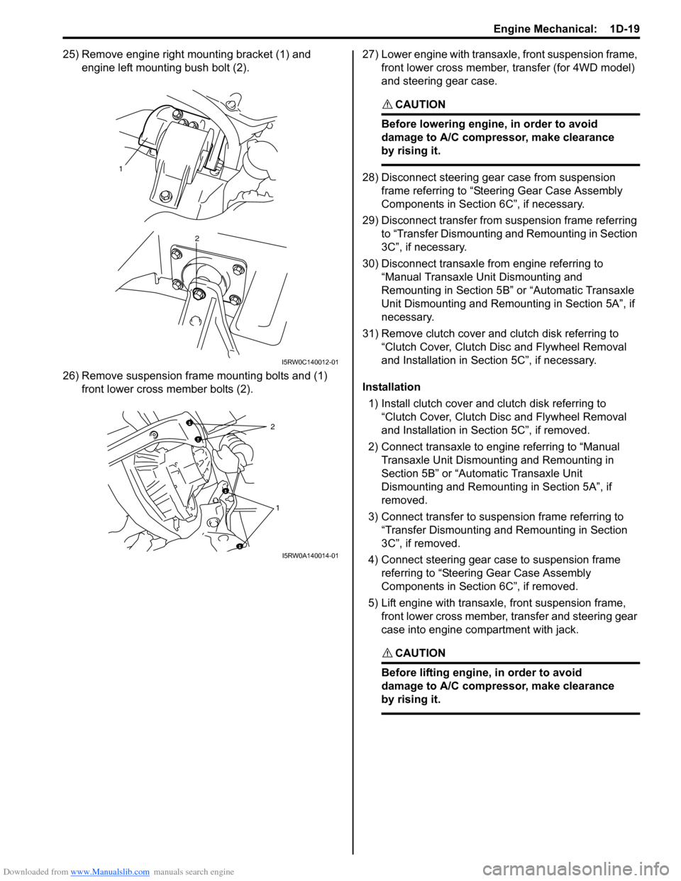
25) Remove engine right mounting bracket (1) and
engine left mounting bush bolt (2).
26) Remove suspension frame mounting bolts and (1)
front lower cross member bolts (2).27) Lower engine with transaxle, front suspension frame,
front lower cross member, transfer (for 4WD model)
and steering gear case.
CAUTION!
Before lowering engine, in order to avoid
damage to A/C compressor, make clearance
by rising it.
28) Disconnect steering gear case from suspension
frame referring to “Steering Gear Case Assembly
Components in Section 6C”, if necessary.
29) Disconnect transfer from suspension frame referring
to “Transfer Dismounting and Remounting in Section
3C”, if necessary.
30) Disconnect transaxle from engine referring to
“Manual Transaxle Unit Dismounting and
Remounting in Section 5B” or “Automatic Transaxle
Unit Dismounting and Remounting in Section 5A”, if
necessary.
31) Remove clutch cover and clutch disk referring to
“Clutch Cover, Clutch Disc and Flywheel Removal
and Installation in Section 5C”, if necessary.
Installation
1) Install clutch cover and clutch disk referring to
“Clutch Cover, Clutch Disc and Flywheel Removal
and Installation in Section 5C”, if removed.
2) Connect transaxle to engine referring to “Manual
Transaxle Unit Dismounting and Remounting in
Section 5B” or “Automatic Transaxle Unit
Dismounting and Remounting in Section 5A”, if
removed.
3) Connect transfer to suspension frame referring to
“Transfer Dismounting and Remounting in Section
3C”, if removed.
4) Connect steering gear case to suspension frame
referring to “Steering Gear Case Assembly
Components in Section 6C”, if removed.
5) Lift engine with transaxle, front suspension frame,
front lower cross member, transfer and steering gear
case into engine compartment with jack.
CAUTION!
Before lifting engine, in order to avoid
damage to A/C compressor, make clearance
by rising it.
1
2
I5RW0C140012-01
2
1
I5RW0A140014-01
Page 356 of 1556
Downloaded from www.Manualslib.com manuals search engine 1D-74 Engine Mechanical:
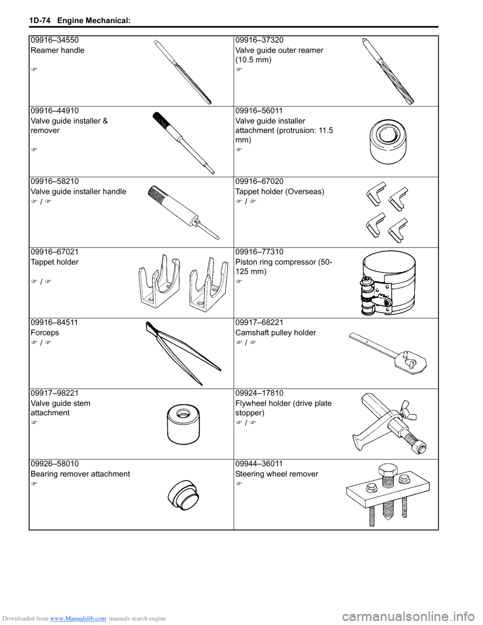
09916–34550 09916–37320
Reamer handle Valve guide outer reamer
(10.5 mm)
))
09916–44910 09916–56011
Valve guide installer &
removerValve guide installer
attachment (protrusion: 11.5
mm)
))
09916–58210 09916–67020
Valve guide installer handle Tappet holder (Overseas)
) / )) / )
09916–67021 09916–77310
Tappet holder Piston ring compressor (50-
125 mm)
) / ))
09916–84511 09917–68221
Forceps Camshaft pulley holder
) / )) / )
09917–98221 09924–17810
Valve guide stem
attachmentFlywheel holder (drive plate
stopper)
)) / )
09926–58010 09944–36011
Bearing remover attachment Steering wheel remover
))
Page 433 of 1556
Downloaded from www.Manualslib.com manuals search engine Table of Contents 2- i
2
Section 2
CONTENTS
Suspension
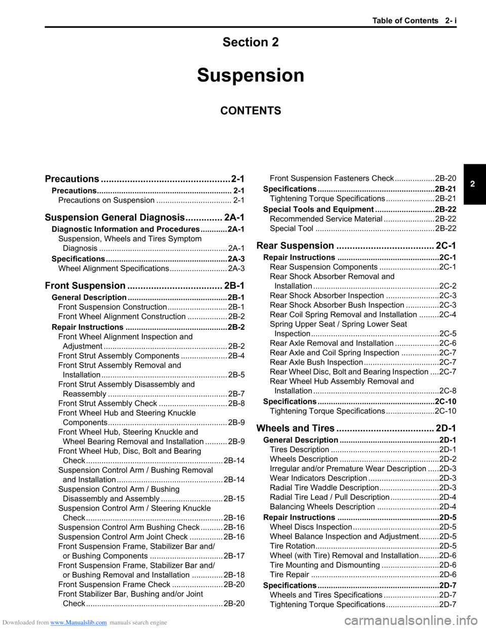
Precautions ................................................. 2-1
Precautions............................................................. 2-1
Precautions on Suspension .................................. 2-1
Suspension General Diagnosis.............. 2A-1
Diagnostic Information and Procedures ............ 2A-1
Suspension, Wheels and Tires Symptom
Diagnosis .......................................................... 2A-1
Specifications....................................................... 2A-3
Wheel Alignment Specifications .......................... 2A-3
Front Suspension .................................... 2B-1
General Description ............................................. 2B-1
Front Suspension Construction ........................... 2B-1
Front Wheel Alignment Construction .................. 2B-2
Repair Instructions .............................................. 2B-2
Front Wheel Alignment Inspection and
Adjustment ........................................................ 2B-2
Front Strut Assembly Components ..................... 2B-4
Front Strut Assembly Removal and
Installation ......................................................... 2B-5
Front Strut Assembly Disassembly and
Reassembly ...................................................... 2B-7
Front Strut Assembly Check ............................... 2B-8
Front Wheel Hub and Steering Knuckle
Components...................................................... 2B-9
Front Wheel Hub, Steering Knuckle and
Wheel Bearing Removal and Installation .......... 2B-9
Front Wheel Hub, Disc, Bolt and Bearing
Check .............................................................. 2B-14
Suspension Control Arm / Bushing Removal
and Installation ................................................ 2B-14
Suspension Control Arm / Bushing
Disassembly and Assembly ............................ 2B-15
Suspension Control Arm / Steering Knuckle
Check .............................................................. 2B-16
Suspension Control Arm Bushing Check .......... 2B-16
Suspension Control Arm Joint Check ............... 2B-16
Front Suspension Frame, Stabilizer Bar and/
or Bushing Components ................................. 2B-17
Front Suspension Frame, Stabilizer Bar and/
or Bushing Removal and Installation .............. 2B-18
Front Suspension Frame Check ....................... 2B-20
Front Stabilizer Bar, Bushing and/or Joint
Check .............................................................. 2B-20Front Suspension Fasteners Check .................. 2B-20
Specifications .....................................................2B-21
Tightening Torque Specifications ...................... 2B-21
Special Tools and Equipment ...........................2B-22
Recommended Service Material ....................... 2B-22
Special Tool ...................................................... 2B-22
Rear Suspension ..................................... 2C-1
Repair Instructions ..............................................2C-1
Rear Suspension Components ...........................2C-1
Rear Shock Absorber Removal and
Installation .........................................................2C-2
Rear Shock Absorber Inspection ........................2C-3
Rear Shock Absorber Bush Inspection ...............2C-3
Rear Coil Spring Removal and Installation .........2C-4
Spring Upper Seat / Spring Lower Seat
Inspection ..........................................................2C-5
Rear Axle Removal and Installation ....................2C-6
Rear Axle and Coil Spring Inspection .................2C-7
Rear Axle Bush Inspection ..................................2C-7
Rear Wheel Disc, Bolt and Bearing Inspection ....2C-7
Rear Wheel Hub Assembly Removal and
Installation .........................................................2C-8
Specifications .....................................................2C-10
Tightening Torque Specifications ......................2C-10
Wheels and Tires ..................................... 2D-1
General Description .............................................2D-1
Tires Description .................................................2D-1
Wheels Description .............................................2D-2
Irregular and/or Premature Wear Description .....2D-3
Wear Indicators Description ................................2D-3
Radial Tire Waddle Description...........................2D-3
Radial Tire Lead / Pull Description ......................2D-4
Balancing Wheels Description ............................2D-4
Repair Instructions ..............................................2D-5
Wheel Discs Inspection .......................................2D-5
Wheel Balance Inspection and Adjustment.........2D-5
Tire Rotation........................................................2D-5
Wheel (with Tire) Removal and Installation.........2D-6
Tire Mounting and Dismounting ..........................2D-6
Tire Repair ..........................................................2D-6
Specifications .......................................................2D-7
Wheels and Tires Specifications .........................2D-7
Tightening Torque Specifications ........................2D-7
Page 435 of 1556
Downloaded from www.Manualslib.com manuals search engine Suspension General Diagnosis: 2A-1
Suspension
Suspension General Diagnosis
Diagnostic Information and Procedures
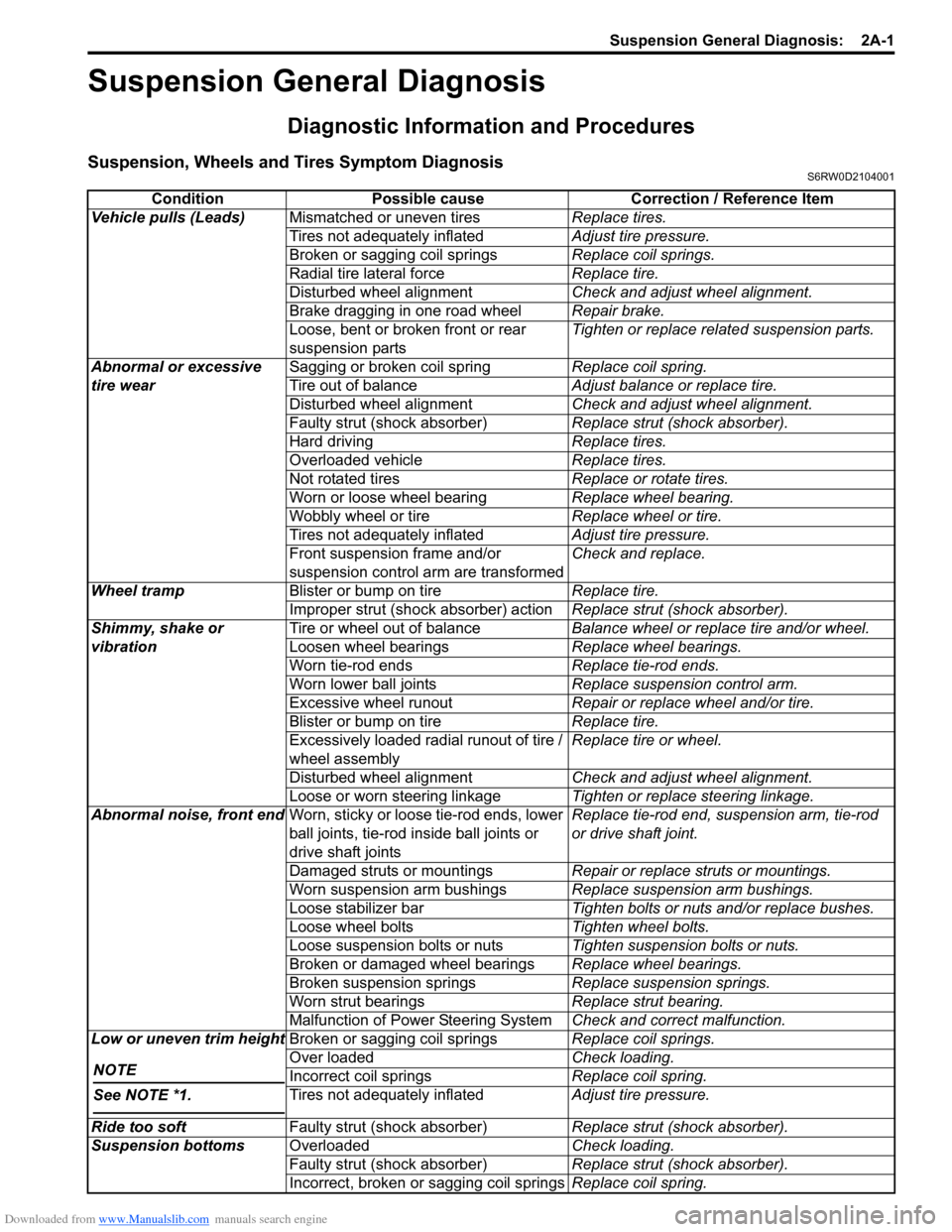
Suspension, Wheels and Tires Symptom DiagnosisS6RW0D2104001
Condition Possible cause Correction / Reference Item
Vehicle pulls (Leads)Mismatched or uneven tiresReplace tires.
Tires not adequately inflatedAdjust tire pressure.
Broken or sagging coil springsReplace coil springs.
Radial tire lateral forceReplace tire.
Disturbed wheel alignmentCheck and adjust wheel alignment.
Brake dragging in one road wheelRepair brake.
Loose, bent or broken front or rear
suspension partsTighten or replace related suspension parts.
Abnormal or excessive
tire wearSagging or broken coil springReplace coil spring.
Tire out of balanceAdjust balance or replace tire.
Disturbed wheel alignmentCheck and adjust wheel alignment.
Faulty strut (shock absorber)Replace strut (shock absorber).
Hard drivingReplace tires.
Overloaded vehicleReplace tires.
Not rotated tiresReplace or rotate tires.
Worn or loose wheel bearingReplace wheel bearing.
Wobbly wheel or tireReplace wheel or tire.
Tires not adequately inflatedAdjust tire pressure.
Front suspension frame and/or
suspension control arm are transformedCheck and replace.
Wheel trampBlister or bump on tireReplace tire.
Improper strut (shock absorber) actionReplace strut (shock absorber).
Shimmy, shake or
vibrationTire or wheel out of balanceBalance wheel or replace tire and/or wheel.
Loosen wheel bearingsReplace wheel bearings.
Worn tie-rod endsReplace tie-rod ends.
Worn lower ball jointsReplace suspension control arm.
Excessive wheel runoutRepair or replace wheel and/or tire.
Blister or bump on tireReplace tire.
Excessively loaded radial runout of tire /
wheel assemblyReplace tire or wheel.
Disturbed wheel alignmentCheck and adjust wheel alignment.
Loose or worn steering linkageTighten or replace steering linkage.
Abnormal noise, front endWorn, sticky or loose tie-rod ends, lower
ball joints, tie-rod inside ball joints or
drive shaft jointsReplace tie-rod end, suspension arm, tie-rod
or drive shaft joint.
Damaged struts or mountingsRepair or replace struts or mountings.
Worn suspension arm bushingsReplace suspension arm bushings.
Loose stabilizer barTighten bolts or nuts and/or replace bushes.
Loose wheel boltsTighten wheel bolts.
Loose suspension bolts or nutsTighten suspension bolts or nuts.
Broken or damaged wheel bearingsReplace wheel bearings.
Broken suspension springsReplace suspension springs.
Worn strut bearingsReplace strut bearing.
Malfunction of Power Steering SystemCheck and correct malfunction.
Low or uneven trim height
NOTE
See NOTE *1.
Broken or sagging coil springsReplace coil springs.
Over loadedCheck loading.
Incorrect coil springsReplace coil spring.
Tires not adequately inflatedAdjust tire pressure.
Ride too softFaulty strut (shock absorber)Replace strut (shock absorber).
Suspension bottomsOverloadedCheck loading.
Faulty strut (shock absorber)Replace strut (shock absorber).
Incorrect, broken or sagging coil springsReplace coil spring.
Page 437 of 1556
Downloaded from www.Manualslib.com manuals search engine Suspension General Diagnosis: 2A-3
Specifications
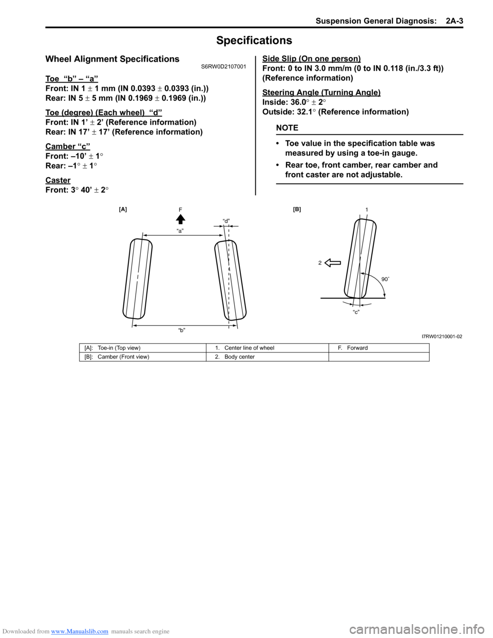
Wheel Alignment SpecificationsS6RW0D2107001
To e “b” – “a”
Front: IN 1 ± 1 mm (IN 0.0393 ± 0.0393 (in.))
Rear: IN 5 ± 5 mm (IN 0.1969 ± 0.1969 (in.))
Toe (degree) (Each wheel)
“d”
Front: IN 1’ ± 2’ (Reference information)
Rear: IN 17’ ± 17’ (Reference information)
Camber
“c”
Front: –10’ ± 1°
Rear: –1° ± 1°
Caster
Front: 3° 40’ ± 2°Side Slip (On one person)
Front: 0 to IN 3.0 mm/m (0 to IN 0.118 (in./3.3 ft))
(Reference information)
Steering Angle (Turning Angle)
Inside: 36.0° ± 2°
Outside: 32.1° (Reference information)
NOTE
• Toe value in the specification table was
measured by using a toe-in gauge.
• Rear toe, front camber, rear camber and
front caster are not adjustable.
“a”“d”
“b”F [A]
21
90
“c” [B]
I7RW01210001-02
[A]: Toe-in (Top view) 1. Center line of wheel F. Forward
[B]: Camber (Front view) 2. Body center
Page 438 of 1556
Downloaded from www.Manualslib.com manuals search engine 2B-1 Front Suspension:
Suspension
Front Suspension
General Description
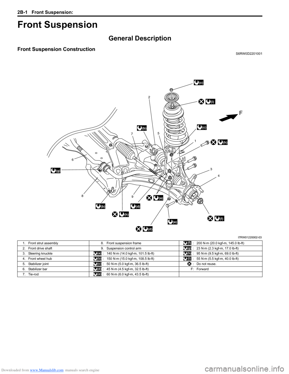
Front Suspension ConstructionS6RW0D2201001
1
4 3
2
7
6
8
))
5
9(a)
(b)
(b)
(b)
(b)
(c)
(c)
(d)
(d)
(e)(f)
(g)
(h)
(i)
(h)
F
I7RW01220002-03
1. Front strut assembly 8. Front suspension frame : 200 N⋅m (20.0 kgf-m, 145.0 lb-ft)
2. Front drive shaft 9. Suspension control arm : 23 N⋅m (2.3 kgf-m, 17.0 lb-ft)
3. Steering knuckle : 140 N⋅m (14.0 kgf-m, 101.5 lb-ft) : 95 N⋅m (9.5 kgf-m, 69.0 lb-ft)
4. Front wheel hub : 150 N⋅m (15.0 kgf-m, 108.5 lb-ft) : 55 N⋅m (5.5 kgf-m, 40.0 lb-ft)
5. Stabilizer joint : 50 N⋅m (5.0 kgf-m, 36.5 lb-ft) : Do not reuse.
6. Stabilizer bar : 45 N⋅m (4.5 kgf-m, 32.5 lb-ft) F: Forward
7. Tie-rod : 60 N⋅m (6.0 kgf-m, 43.5 lb-ft)
Page 439 of 1556
Downloaded from www.Manualslib.com manuals search engine Front Suspension: 2B-2
Front Wheel Alignment ConstructionS6RW0D2201002
Among factors for front wheel alignment, only toe setting
can be adjusted. Camber and caster are not adjustable.
Therefore, should camber or caster be out of
specification due to the damage caused by hazardous
road conditions or collision, whether the damage is in
body or in suspension should be determined and
damaged body should be repaired or damaged
suspension should be replaced.
Preliminary Checks Prior to Adjustment Front Wheel
Alignment
Steering and vibration complaints are not always the
result of improper wheel alignment. An additional item to
be checked is the possibility of tire lead due to worn or
improperly manufactured tires. “Lead” is the vehicle
deviation from a straight path on a level road without
hand pressure on the steering wheel. Refer to “Radial
Tire Lead / Pull Description in Section 2D” in order to
determine if the vehicle has a tire lead problem. Before
making any adjustment affecting wheel alignment, the
following checks and inspections should be made to
ensure correctness of alignment readings and alignment
adjustments:• Check all tires for proper inflation pressures and
approximately the same tread wear.
• Check for loose of ball joints. Check tie-rod ends; if
excessive looseness is noted, it must be corrected
before adjusting.
• Check for run-out of wheels and tires.
• Check vehicle trim heights; if it is out of limit and a
correction is needed, it must be done before adjusting
toe.
• Check for loose of suspension control arms.
• Check for loose or missing stabilizer bar attachments.
• Consideration must be given to excess loads, such as
tool boxes. If this excess load is normally carried in
vehicle, it should remain in vehicle during alignment
checks.
• Consider condition of equipment being used to check
alignment and follow manufacturer’s instructions.
• Regardless of equipment used to check alignment,
vehicle must be placed on a level surface.
NOTE
To prevent possible incorrect reading of toe,
camber or caster, vehicle front and rear end
must be moved up and down a few times
before inspection.
Repair Instructions
Front Wheel Alignment Inspection and
Adjustment
S6RW0D2206001
Toe Inspection and Adjustment
Preparation for toe inspection and adjustment.
• Place vehicle in unloaded state on level surface.
• Set steering wheel in straight state.
• Check that inflation pressure of each tire is adjusted
properly and wheel is free from deflection.
• Check that each suspension part is free from bend,
dent, wear or damage in any other form.
• Check that ground clearance at the right and left is
just about the same.Inspection
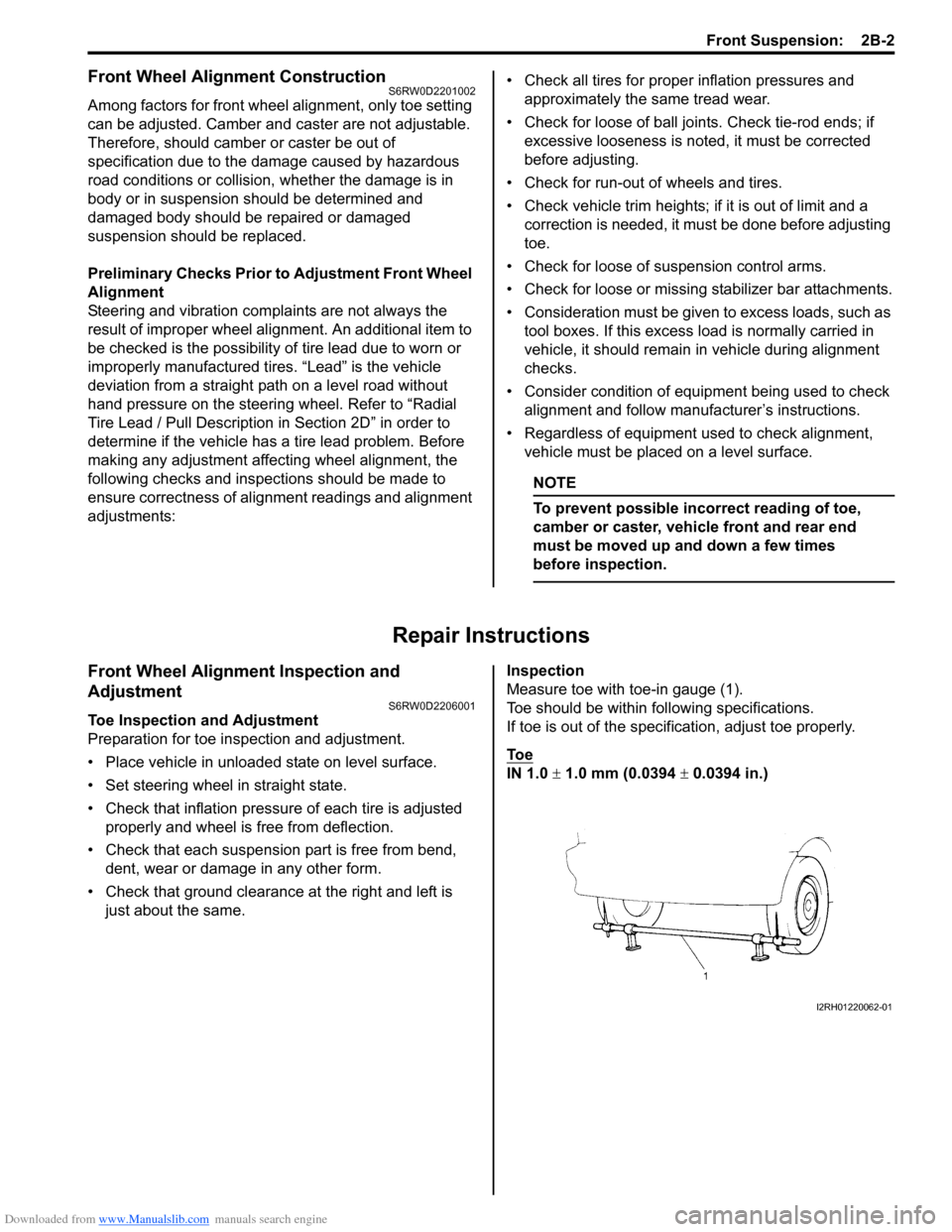
Measure toe with toe-in gauge (1).
Toe should be within following specifications.
If toe is out of the specification, adjust toe properly.
To e
IN 1.0 ± 1.0 mm (0.0394 ± 0.0394 in.)
I2RH01220062-01
Page 440 of 1556
Downloaded from www.Manualslib.com manuals search engine 2B-3 Front Suspension:
Adjustment
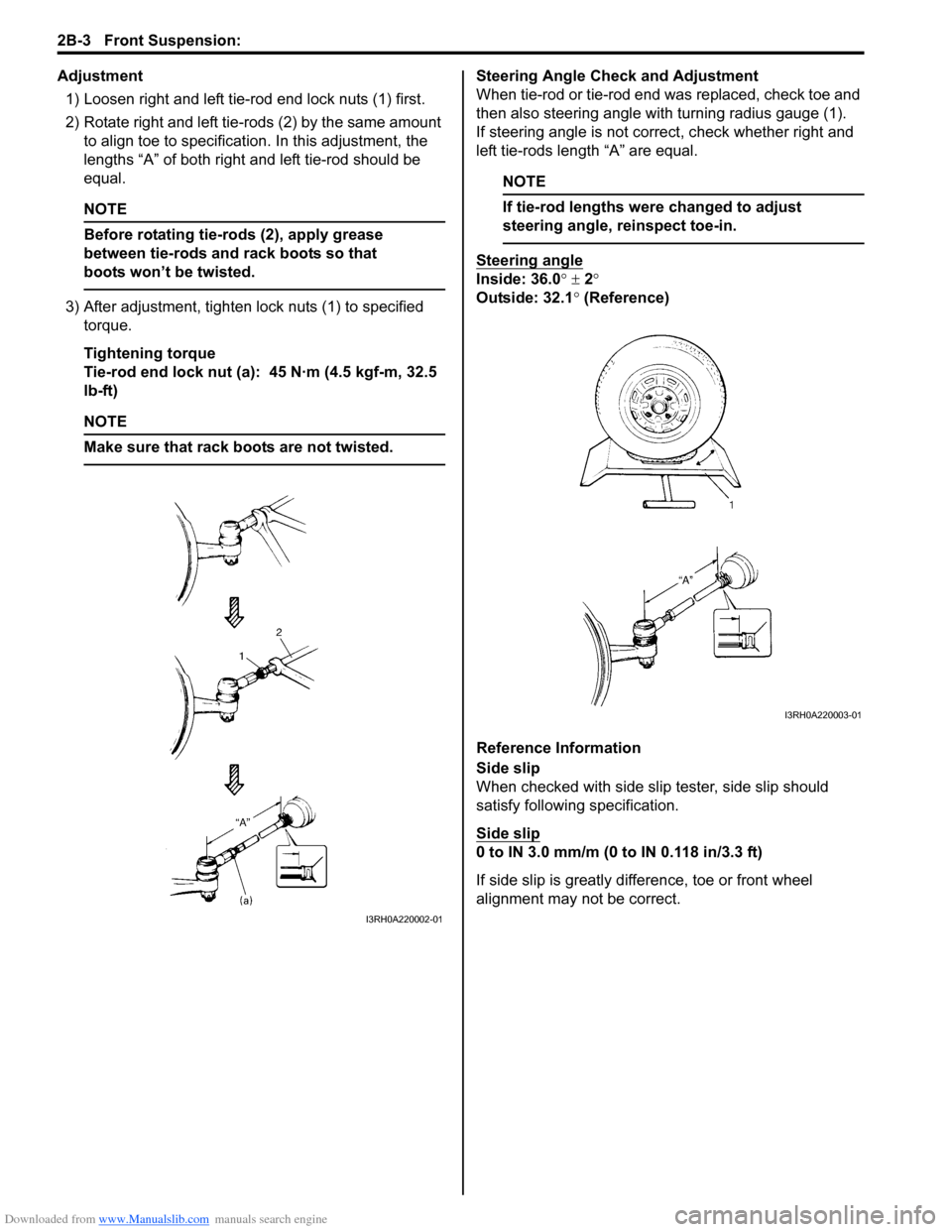
1) Loosen right and left tie-rod end lock nuts (1) first.
2) Rotate right and left tie-rods (2) by the same amount
to align toe to specification. In this adjustment, the
lengths “A” of both right and left tie-rod should be
equal.
NOTE
Before rotating tie-rods (2), apply grease
between tie-rods and rack boots so that
boots won’t be twisted.
3) After adjustment, tighten lock nuts (1) to specified
torque.
Tightening torque
Tie-rod end lock nut (a): 45 N·m (4.5 kgf-m, 32.5
lb-ft)
NOTE
Make sure that rack boots are not twisted.
Steering Angle Check and Adjustment
When tie-rod or tie-rod end was replaced, check toe and
then also steering angle with turning radius gauge (1).
If steering angle is not correct, check whether right and
left tie-rods length “A” are equal.
NOTE
If tie-rod lengths were changed to adjust
steering angle, reinspect toe-in.
Steering angle
Inside: 36.0° ± 2°
Outside: 32.1° (Reference)
Reference Information
Side slip
When checked with side slip tester, side slip should
satisfy following specification.
Side slip
0 to IN 3.0 mm/m (0 to IN 0.118 in/3.3 ft)
If side slip is greatly difference, toe or front wheel
alignment may not be correct.
I3RH0A220002-01
I3RH0A220003-01
Page 446 of 1556
Downloaded from www.Manualslib.com manuals search engine 2B-9 Front Suspension:
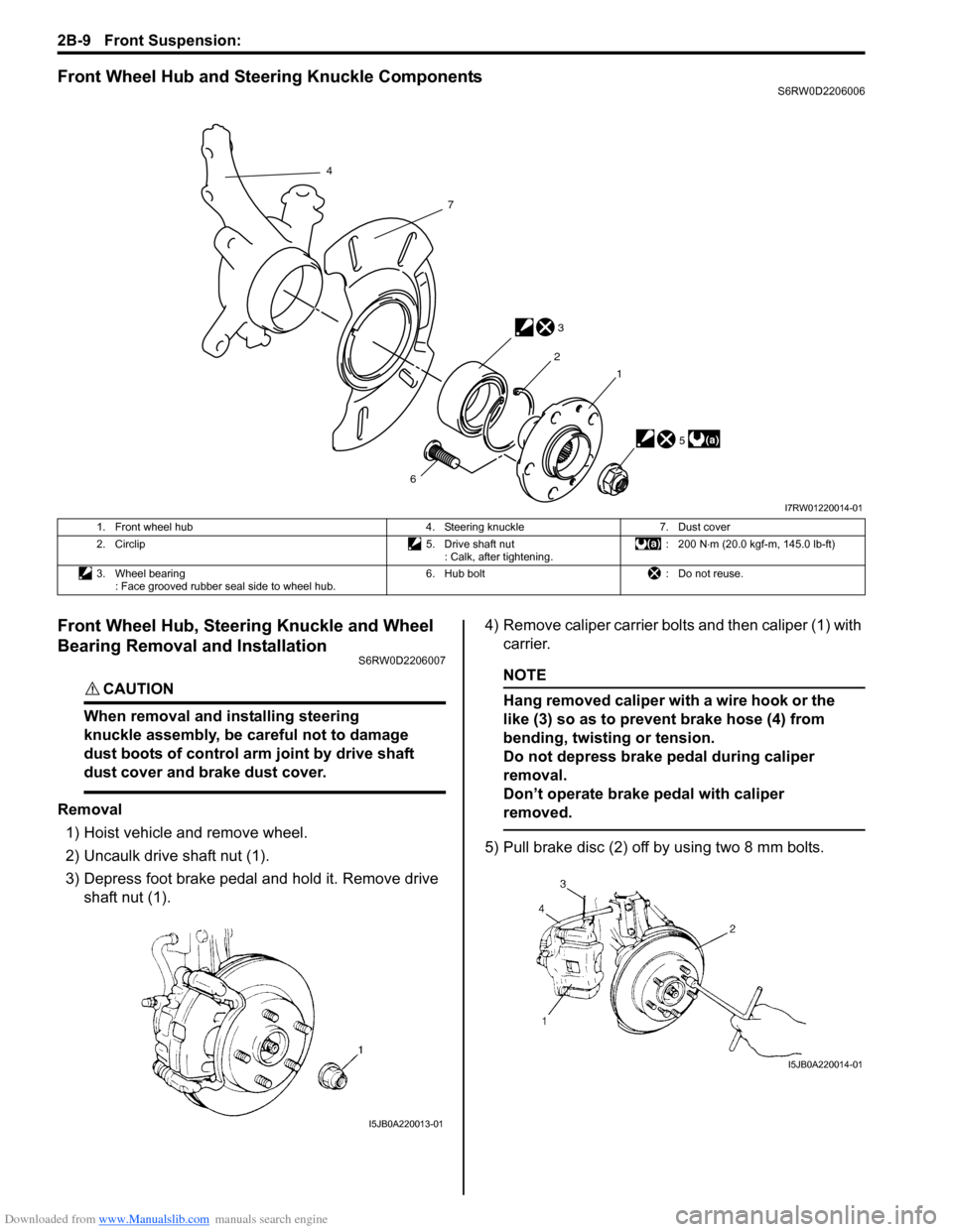
Front Wheel Hub and Steering Knuckle ComponentsS6RW0D2206006
Front Wheel Hub, Steering Knuckle and Wheel
Bearing Removal and Installation
S6RW0D2206007
CAUTION!
When removal and installing steering
knuckle assembly, be careful not to damage
dust boots of control arm joint by drive shaft
dust cover and brake dust cover.
Removal
1) Hoist vehicle and remove wheel.
2) Uncaulk drive shaft nut (1).
3) Depress foot brake pedal and hold it. Remove drive
shaft nut (1).4) Remove caliper carrier bolts and then caliper (1) with
carrier.
NOTE
Hang removed caliper with a wire hook or the
like (3) so as to prevent brake hose (4) from
bending, twisting or tension.
Do not depress brake pedal during caliper
removal.
Don’t operate brake pedal with caliper
removed.
5) Pull brake disc (2) off by using two 8 mm bolts.
(a)5
6 4
3 7
2
1
I7RW01220014-01
1. Front wheel hub 4. Steering knuckle 7. Dust cover
2. Circlip 5. Drive shaft nut
: Calk, after tightening.: 200 N⋅m (20.0 kgf-m, 145.0 lb-ft)
3. Wheel bearing
: Face grooved rubber seal side to wheel hub.6. Hub bolt : Do not reuse.
I5JB0A220013-01
I5JB0A220014-01