tire pressure SUZUKI SX4 2006 1.G Service User Guide
[x] Cancel search | Manufacturer: SUZUKI, Model Year: 2006, Model line: SX4, Model: SUZUKI SX4 2006 1.GPages: 1556, PDF Size: 37.31 MB
Page 475 of 1556
Downloaded from www.Manualslib.com manuals search engine Wheels and Tires: 2D-6
Wheel (with Tire) Removal and InstallationS6RW0D2406003
Removal
CAUTION!
Never use heat to loosen tight wheel because
the application of heat to wheel causes the
wheel life shorter and the wheel bearing
damage.
1) Loosen wheel nuts by approximately 180° (half a
rotation).
2) Hoist vehicle.
3) Make sure that the vehicle will not fall off by trying to
move vehicle body in both ways.
4) Remove wheel nuts except one.
5) Support the wheel and/or tire not to drop the wheel
and then remove the nut left with the wheel.
Installation
For installation, reverse removal procedure, noting the
following.
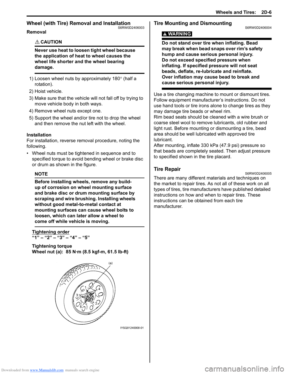
• Wheel nuts must be tightened in sequence and to
specified torque to avoid bending wheel or brake disc
or drum as shown in the figure.
NOTE
Before installing wheels, remove any build-
up of corrosion on wheel mounting surface
and brake disc or drum mounting surface by
scraping and wire brushing. Installing wheels
without good metal-to-metal contact at
mounting surfaces can cause wheel bolts to
loosen, which can later allow a wheel to
come off while vehicle is moving.
Tightening order
“1” – “2” – “3” – “4” – “5”
Tightening torque
Wheel nut (a): 85 N·m (8.5 kgf-m, 61.5 lb-ft)
Tire Mounting and DismountingS6RW0D2406004
WARNING!
Do not stand over tire when inflating. Bead
may break when bead snaps over rim’s safety
hump and cause serious personal injury.
Do not exceed specified pressure when
inflating. If specified pressure will not seat
beads, deflate, re-lubricate and reinflate.
Over inflation may cause bead to break and
cause serious personal injury.
Use a tire changing machine to mount or dismount tires.
Follow equipment manufacturer’s instructions. Do not
use hand tools or tire irons alone to change tires as they
may damage tire beads or wheel rim.
Rim bead seats should be cleaned with a wire brush or
coarse steel wool to remove lubricants, old rubber and
light rust. Before mounting or dismounting a tire, bead
area should be well lubricated with approved tire
lubricant.
After mounting, inflate 330 kPa (47.9 psi) pressure so
that beads are completely seated. Then adjust pressure
to specified shown in the tire placard.
Tire RepairS6RW0D2406005
There are many different materials and techniques on
the market to repair tires. As not all of these work on all
types of tires, tire manufacturers have published detailed
instructions on how and when to repair tires. These
instructions can be obtained from each tire
manufacturer.
IYSQ01240008-01
Page 476 of 1556
Downloaded from www.Manualslib.com manuals search engine 2D-7 Wheels and Tires:
Specifications
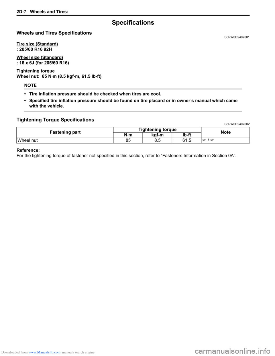
Wheels and Tires SpecificationsS6RW0D2407001
Tire size (Standard)
: 205/60 R16 92H
Wheel size (Standard)
: 16 x 6J (for 205/60 R16)
Tightening torque
Wheel nut: 85 N·m (8.5 kgf-m, 61.5 lb-ft)
NOTE
• Tire inflation pressure should be checked when tires are cool.
• Specified tire inflation pressure should be found on tire placard or in owner’s manual which came
with the vehicle.
Tightening Torque SpecificationsS6RW0D2407002
Reference:
For the tightening torque of fastener not specified in this section, refer to “Fasteners Information in Section 0A”. Fastening partTightening torque
Note
N⋅mkgf-mlb-ft
Wheel nut 85 8.5 61.5) / )
Page 575 of 1556
Downloaded from www.Manualslib.com manuals search engine Brake Control System and Diagnosis: 4A-4
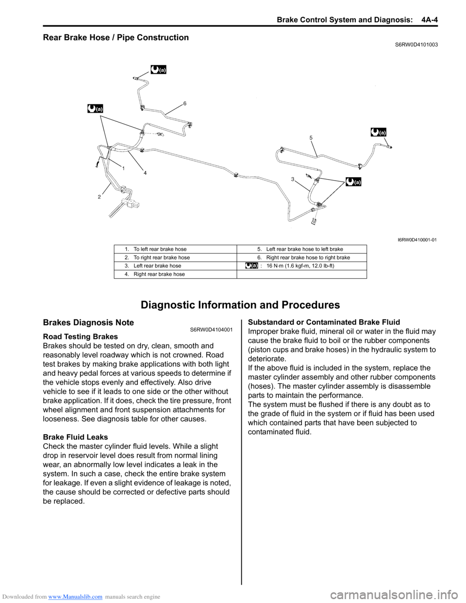
Rear Brake Hose / Pipe ConstructionS6RW0D4101003
Diagnostic Information and Procedures
Brakes Diagnosis NoteS6RW0D4104001
Road Testing Brakes
Brakes should be tested on dry, clean, smooth and
reasonably level roadway which is not crowned. Road
test brakes by making brake applications with both light
and heavy pedal forces at various speeds to determine if
the vehicle stops evenly and effectively. Also drive
vehicle to see if it leads to one side or the other without
brake application. If it does, check the tire pressure, front
wheel alignment and front suspension attachments for
looseness. See diagnosis table for other causes.
Brake Fluid Leaks
Check the master cylinder fluid levels. While a slight
drop in reservoir level does result from normal lining
wear, an abnormally low level indicates a leak in the
system. In such a case, check the entire brake system
for leakage. If even a slight evidence of leakage is noted,
the cause should be corrected or defective parts should
be replaced.Substandard or Contaminated Brake Fluid
Improper brake fluid, mineral oil or water in the fluid may
cause the brake fluid to boil or the rubber components
(piston cups and brake hoses) in the hydraulic system to
deteriorate.
If the above fluid is included in the system, replace the
master cylinder assembly and other rubber components
(hoses). The master cylinder assembly is disassemble
parts to maintain the performance.
The system must be flushed if there is any doubt as to
the grade of fluid in the system or if fluid has been used
which contained parts that have been subjected to
contaminated fluid.
I6RW0D410001-01
1. To left rear brake hose 5. Left rear brake hose to left brake
2. To right rear brake hose 6. Right rear brake hose to right brake
3. Left rear brake hose : 16 N⋅m (1.6 kgf-m, 12.0 lb-ft)
4. Right rear brake hose
Page 580 of 1556
Downloaded from www.Manualslib.com manuals search engine 4A-9 Brake Control System and Diagnosis:
1) Fill master cylinder reservoir with specified brake
fluid and keep at least one-half full of fluid during
bleeding operation.
Brake fluid
: Refer to reservoir cap
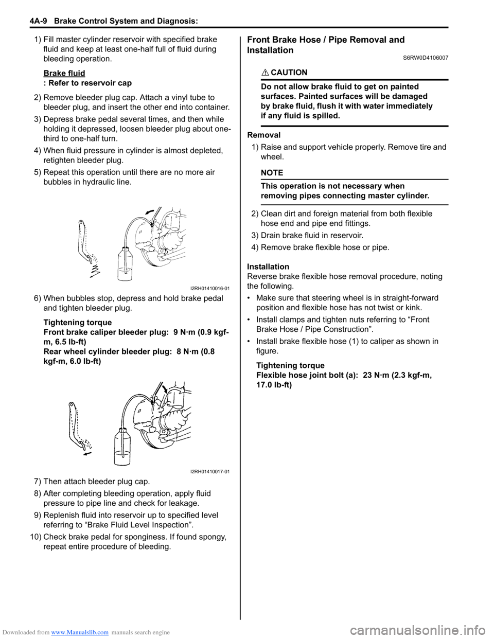
2) Remove bleeder plug cap. Attach a vinyl tube to
bleeder plug, and insert the other end into container.
3) Depress brake pedal several times, and then while
holding it depressed, loosen bleeder plug about one-
third to one-half turn.
4) When fluid pressure in cylinder is almost depleted,
retighten bleeder plug.
5) Repeat this operation until there are no more air
bubbles in hydraulic line.
6) When bubbles stop, depress and hold brake pedal
and tighten bleeder plug.
Tightening torque
Front brake caliper bleeder plug: 9 N·m (0.9 kgf-
m, 6.5 lb-ft)
Rear wheel cylinder bleeder plug: 8 N·m (0.8
kgf-m, 6.0 lb-ft)
7) Then attach bleeder plug cap.
8) After completing bleeding operation, apply fluid
pressure to pipe line and check for leakage.
9) Replenish fluid into reservoir up to specified level
referring to “Brake Fluid Level Inspection”.
10) Check brake pedal for sponginess. If found spongy,
repeat entire procedure of bleeding.
Front Brake Hose / Pipe Removal and
Installation
S6RW0D4106007
CAUTION!
Do not allow brake fluid to get on painted
surfaces. Painted surfaces will be damaged
by brake fluid, flush it with water immediately
if any fluid is spilled.
Removal
1) Raise and support vehicle properly. Remove tire and
wheel.
NOTE
This operation is not necessary when
removing pipes connecting master cylinder.
2) Clean dirt and foreign material from both flexible
hose end and pipe end fittings.
3) Drain brake fluid in reservoir.
4) Remove brake flexible hose or pipe.
Installation
Reverse brake flexible hose removal procedure, noting
the following.
• Make sure that steering wheel is in straight-forward
position and flexible hose has not twist or kink.
• Install clamps and tighten nuts referring to “Front
Brake Hose / Pipe Construction”.
• Install brake flexible hose (1) to caliper as shown in
figure.
Tightening torque
Flexible hose joint bolt (a): 23 N·m (2.3 kgf-m,
17.0 lb-ft)
I2RH01410016-01
I2RH01410017-01
Page 629 of 1556

Downloaded from www.Manualslib.com manuals search engine ABS: 4E-24
DTC Troubleshooting
Step Action Yes No
1Was “ABS Check” performed?Go to Step 2. Go to “ABS Check”.
2Check tire condition
1) Check that tire pressure is specifications.
Are they in good condition?Go to Step 3. Replace tire or adjust
tire pressure and
recheck.
3Wheel speed sensor circuit check
1) Disconnect ABS hydraulic unit / control module
connector and applicable wheel speed sensor connector
with ignition switch turned OFF.
2) Check for proper connection to ABS hydraulic unit /
control module connector at applicable terminals and
terminals of applicable wheel speed sensor.
3) If OK then check applicable wheel speed sensor circuit
for open, short and high resistance.
Is each applicable wheel speed sensor circuit in good
condition?Go to Step 4. Repair circuit and
recheck
4Wheel speed sensor check
1) Inspection applicable wheel speed sensor referring to
“Front and Rear Wheel Speed Sensor Inspection”.
Is it in good condition?Go to Step 5. Clean or replace.
5Wheel speed sensor encoder check
1) Inspection applicable wheel speed sensor encoder
referring to “Front Wheel Speed Sensor Encoder On-
Vehicle Inspection” and/or “Rear Wheel Speed Sensor
Encoder On-Vehicle Inspection”.
Is it in good condition?Go to Step 6. Clean or replace wheel
hub assembly.
6Wheel speed sensor signal check
1) Inspection applicable wheel speed sensor referring to
“Front and Rear Wheel Speed Sensor On-Vehicle
Inspection”.
Is it in good condition?Substitute a known-
good wheel hub
assembly and recheck.
If DTC detected,
substitute a known-
good ABS hydraulic unit
/ control module and
recheck.Replace wheel speed
sensor and recheck.
Page 630 of 1556
Downloaded from www.Manualslib.com manuals search engine 4E-25 ABS:
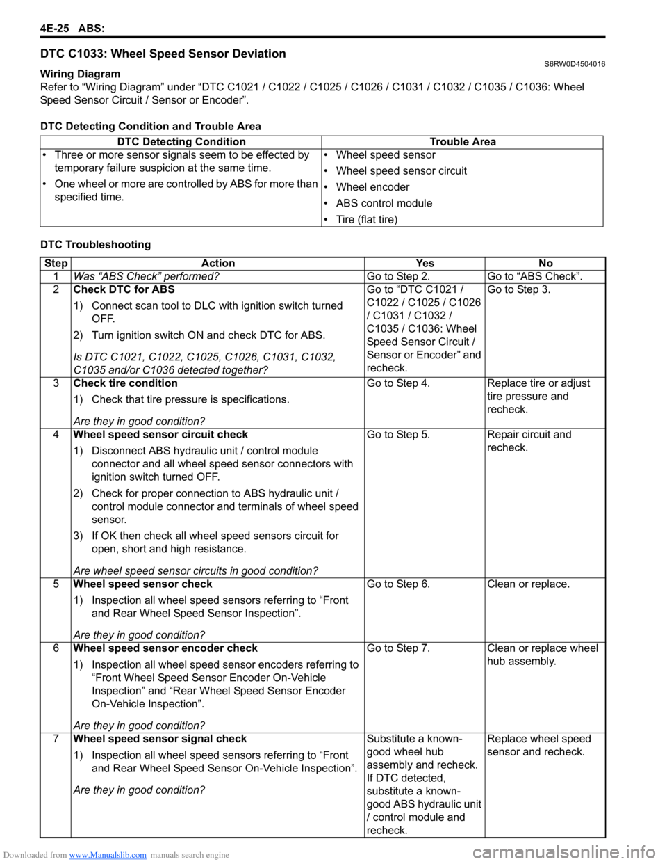
DTC C1033: Wheel Speed Sensor DeviationS6RW0D4504016
Wiring Diagram
Refer to “Wiring Diagram” under “DTC C1021 / C1022 / C1025 / C1026 / C1031 / C1032 / C1035 / C1036: Wheel
Speed Sensor Circuit / Sensor or Encoder”.
DTC Detecting Condition and Trouble Area
DTC Troubleshooting DTC Detecting Condition Trouble Area
• Three or more sensor signals seem to be effected by
temporary failure suspicion at the same time.
• One wheel or more are controlled by ABS for more than
specified time.• Wheel speed sensor
• Wheel speed sensor circuit
• Wheel encoder
• ABS control module
• Tire (flat tire)
Step Action Yes No
1Was “ABS Check” performed?Go to Step 2. Go to “ABS Check”.
2Check DTC for ABS
1) Connect scan tool to DLC with ignition switch turned
OFF.
2) Turn ignition switch ON and check DTC for ABS.
Is DTC C1021, C1022, C1025, C1026, C1031, C1032,
C1035 and/or C1036 detected together?Go to “DTC C1021 /
C1022 / C1025 / C1026
/ C1031 / C1032 /
C1035 / C1036: Wheel
Speed Sensor Circuit /
Sensor or Encoder” and
recheck.Go to Step 3.
3Check tire condition
1) Check that tire pressure is specifications.
Are they in good condition?Go to Step 4. Replace tire or adjust
tire pressure and
recheck.
4Wheel speed sensor circuit check
1) Disconnect ABS hydraulic unit / control module
connector and all wheel speed sensor connectors with
ignition switch turned OFF.
2) Check for proper connection to ABS hydraulic unit /
control module connector and terminals of wheel speed
sensor.
3) If OK then check all wheel speed sensors circuit for
open, short and high resistance.
Are wheel speed sensor circuits in good condition?Go to Step 5. Repair circuit and
recheck.
5Wheel speed sensor check
1) Inspection all wheel speed sensors referring to “Front
and Rear Wheel Speed Sensor Inspection”.
Are they in good condition?Go to Step 6. Clean or replace.
6Wheel speed sensor encoder check
1) Inspection all wheel speed sensor encoders referring to
“Front Wheel Speed Sensor Encoder On-Vehicle
Inspection” and “Rear Wheel Speed Sensor Encoder
On-Vehicle Inspection”.
Are they in good condition?Go to Step 7. Clean or replace wheel
hub assembly.
7Wheel speed sensor signal check
1) Inspection all wheel speed sensors referring to “Front
and Rear Wheel Speed Sensor On-Vehicle Inspection”.
Are they in good condition?Substitute a known-
good wheel hub
assembly and recheck.
If DTC detected,
substitute a known-
good ABS hydraulic unit
/ control module and
recheck.Replace wheel speed
sensor and recheck.
Page 868 of 1556
Downloaded from www.Manualslib.com manuals search engine 6A-1 Steering General Diagnosis:
Ste eri ng
Steering General Diagnosis
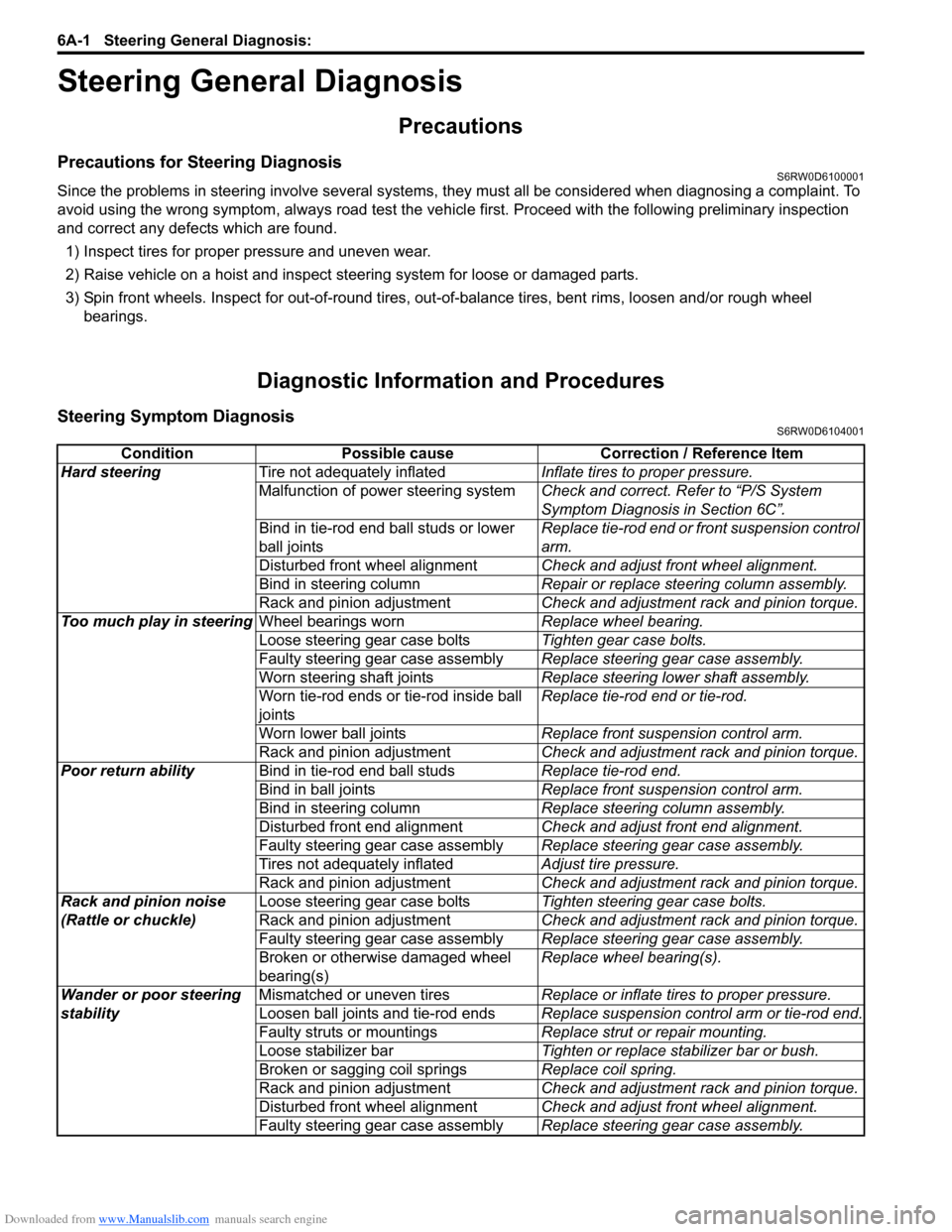
Precautions
Precautions for Steering DiagnosisS6RW0D6100001
Since the problems in steering involve several systems, they must all be considered when diagnosing a complaint. To
avoid using the wrong symptom, always road test the vehicle first. Proceed with the following preliminary inspection
and correct any defects which are found.
1) Inspect tires for proper pressure and uneven wear.
2) Raise vehicle on a hoist and inspect steering system for loose or damaged parts.
3) Spin front wheels. Inspect for out-of-round tires, out-of-balance tires, bent rims, loosen and/or rough wheel
bearings.
Diagnostic Information and Procedures
Steering Symptom DiagnosisS6RW0D6104001
Condition Possible cause Correction / Reference Item
Hard steeringTire not adequately inflatedInflate tires to proper pressure.
Malfunction of power steering systemCheck and correct. Refer to “P/S System
Symptom Diagnosis in Section 6C”.
Bind in tie-rod end ball studs or lower
ball jointsReplace tie-rod end or front suspension control
arm.
Disturbed front wheel alignmentCheck and adjust front wheel alignment.
Bind in steering columnRepair or replace steering column assembly.
Rack and pinion adjustmentCheck and adjustment rack and pinion torque.
Too much play in steeringWheel bearings wornReplace wheel bearing.
Loose steering gear case boltsTighten gear case bolts.
Faulty steering gear case assemblyReplace steering gear case assembly.
Worn steering shaft jointsReplace steering lower shaft assembly.
Worn tie-rod ends or tie-rod inside ball
jointsReplace tie-rod end or tie-rod.
Worn lower ball jointsReplace front suspension control arm.
Rack and pinion adjustmentCheck and adjustment rack and pinion torque.
Poor return abilityBind in tie-rod end ball studsReplace tie-rod end.
Bind in ball jointsReplace front suspension control arm.
Bind in steering columnReplace steering column assembly.
Disturbed front end alignmentCheck and adjust front end alignment.
Faulty steering gear case assemblyReplace steering gear case assembly.
Tires not adequately inflatedAdjust tire pressure.
Rack and pinion adjustmentCheck and adjustment rack and pinion torque.
Rack and pinion noise
(Rattle or chuckle)Loose steering gear case boltsTighten steering gear case bolts.
Rack and pinion adjustmentCheck and adjustment rack and pinion torque.
Faulty steering gear case assemblyReplace steering gear case assembly.
Broken or otherwise damaged wheel
bearing(s)Replace wheel bearing(s).
Wander or poor steering
stabilityMismatched or uneven tiresReplace or inflate tires to proper pressure.
Loosen ball joints and tie-rod endsReplace suspension control arm or tie-rod end.
Faulty struts or mountingsReplace strut or repair mounting.
Loose stabilizer barTighten or replace stabilizer bar or bush.
Broken or sagging coil springsReplace coil spring.
Rack and pinion adjustmentCheck and adjustment rack and pinion torque.
Disturbed front wheel alignmentCheck and adjust front wheel alignment.
Faulty steering gear case assemblyReplace steering gear case assembly.
Page 869 of 1556
Downloaded from www.Manualslib.com manuals search engine Steering General Diagnosis: 6A-2
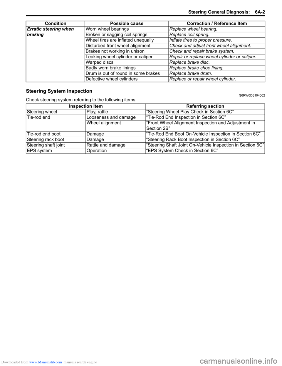
Steering System InspectionS6RW0D6104002
Check steering system referring to the following items.Erratic steering when
brakingWorn wheel bearingsReplace wheel bearing.
Broken or sagging coil springsReplace coil spring.
Wheel tires are inflated unequallyInflate tires to proper pressure.
Disturbed front wheel alignmentCheck and adjust front wheel alignment.
Brakes not working in unisonCheck and repair brake system.
Leaking wheel cylinder or caliperRepair or replace wheel cylinder or caliper.
Warped discsReplace brake disc.
Badly worn brake liningsReplace brake shoe lining.
Drum is out of round in some brakesReplace brake drum.
Defective wheel cylindersReplace or repair wheel cylinder. Condition Possible cause Correction / Reference Item
Inspection Item Referring section
Steering wheel Play, rattle “Steering Wheel Play Check in Section 6C”
Tie-rod end Looseness and damage “Tie-Rod End Inspection in Section 6C”
Wheel alignment “Front Wheel Alignment Inspection and Adjustment in
Section 2B”
Tie-rod end boot Damage “Tie-Rod End Boot On-Vehicle Inspection in Section 6C”
Steering rack boot Damage “Steering Rack Boot Inspection in Section 6C”
Steering shaft joint Rattle and damage “Steering Shaft Joint On-Vehicle Inspection in Section 6C”
EPS system Operation “EPS System Check in Section 6C”
Page 914 of 1556
Downloaded from www.Manualslib.com manuals search engine 6C-34 Power Assisted Steering System:
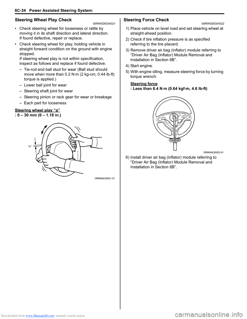
Steering Wheel Play CheckS6RW0D6304021
• Check steering wheel for looseness or rattle by
moving it in its shaft direction and lateral direction.
If found defective, repair or replace.
• Check steering wheel for play, holding vehicle in
straight forward condition on the ground with engine
stopped.
If steering wheel play is not within specification,
inspect as follows and replace if found defective.
– Tie-rod end ball stud for wear (Ball stud should
move when more than 0.2 N⋅m (2 kg-cm, 0.44 lb-ft)
torque is applied.)
– Lower ball joint for wear
– Steering shaft joint for wear
– Steering pinion or rack gear for wear or breakage
– Each part for looseness
Steering wheel play
“a”
: 0 – 30 mm (0 – 1.18 in.)
Steering Force CheckS6RW0D6304022
1) Place vehicle on level road and set steering wheel at
straight-ahead position.
2) Check if tire inflation pressure is as specified
referring to the tire placard.
3) Remove driver air bag (inflator) module referring to
“Driver Air Bag (Inflator) Module Removal and
Installation in Section 8B”.
4) Start engine.
5) With engine idling, measure steering force by turning
torque wrench.
Steering force
: Less than 6.4 N⋅m (0.64 kgf-m, 4.6 lb-ft)
6) Install driver air bag (inflator) module referring to
“Driver Air Bag (Inflator) Module Removal and
Installation in Section 8B”.
I3RM0A630021-01
I3RM0A630022-01
Page 1168 of 1556
Downloaded from www.Manualslib.com manuals search engine 9A-1 Wiring Systems:
Body, Cab and Accessories
Wiring Systems
Precautions
Cautions in Body Electrical System ServicingS6RW0D9100001
When servicing the electric systems, observe the cautions described in “Air Bag Warning in Section 00” to protect
electrical parts and to prevent a fire.
General Description
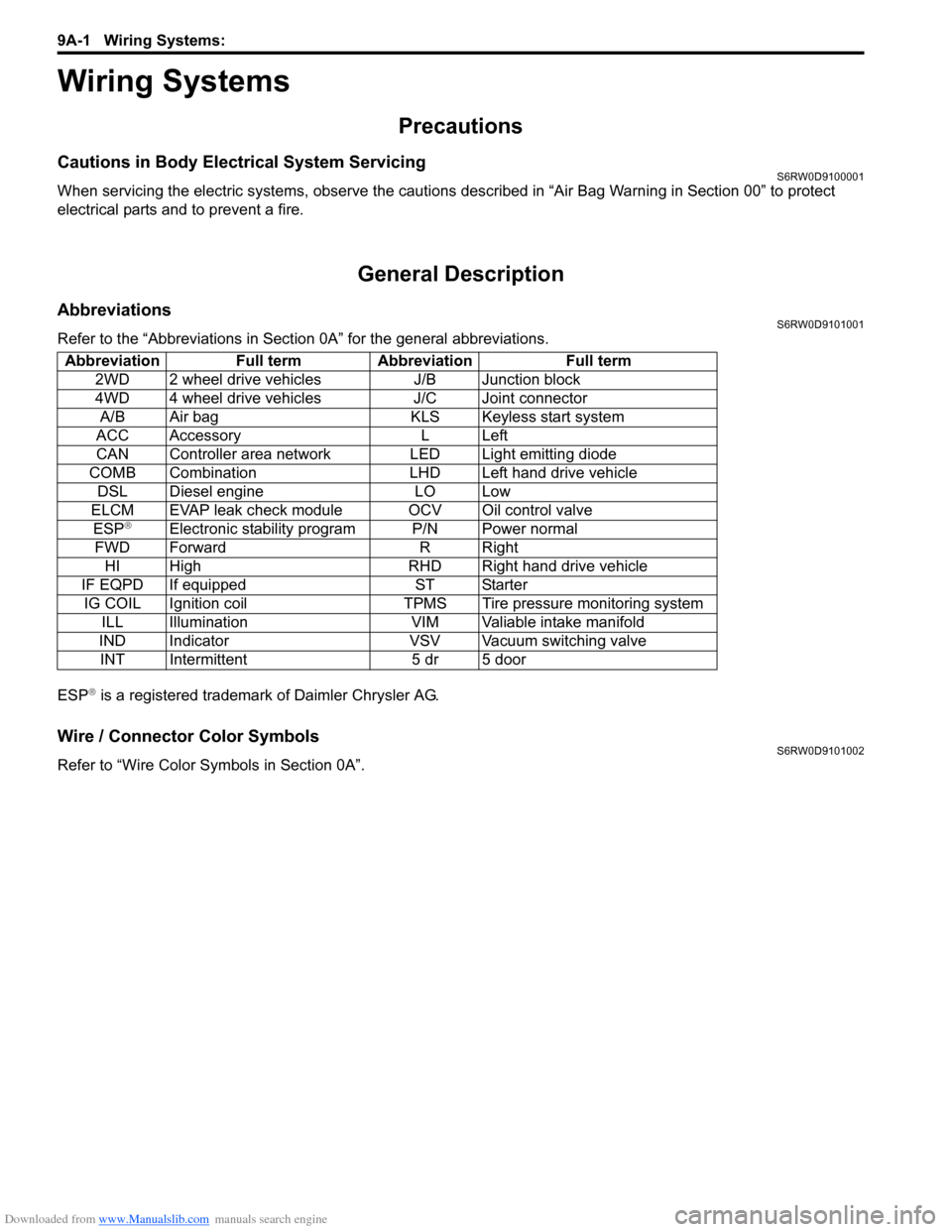
AbbreviationsS6RW0D9101001
Refer to the “Abbreviations in Section 0A” for the general abbreviations.
ESP
® is a registered trademark of Daimler Chrysler AG.
Wire / Connector Color SymbolsS6RW0D9101002
Refer to “Wire Color Symbols in Section 0A”. Abbreviation Full term Abbreviation Full term
2WD 2 wheel drive vehicles J/B Junction block
4WD 4 wheel drive vehicles J/C Joint connector
A/B Air bag KLS Keyless start system
ACC Accessory L Left
CAN Controller area network LED Light emitting diode
COMB Combination LHD Left hand drive vehicle
DSL Diesel engine LO Low
ELCM EVAP leak check module OCV Oil control valve
ESP
®Electronic stability program P/N Power normal
FWD Forward R Right
HI High RHD Right hand drive vehicle
IF EQPD If equipped ST Starter
IG COIL Ignition coil TPMS Tire pressure monitoring system
ILL Illumination VIM Valiable intake manifold
IND Indicator VSV Vacuum switching valve
INT Intermittent 5 dr 5 door