trim SUZUKI SX4 2006 1.G Service User Guide
[x] Cancel search | Manufacturer: SUZUKI, Model Year: 2006, Model line: SX4, Model: SUZUKI SX4 2006 1.GPages: 1556, PDF Size: 37.31 MB
Page 462 of 1556
Downloaded from www.Manualslib.com manuals search engine 2C-3 Rear Suspension:
3) Remove floor jack from rear axle.
4) Install rear wheel and tighten wheel nuts to specified
torque.
Tightening torque
Wheel nut: 85 N·m (8.5 kgf-m, 61.5 lb-ft)
5) Lower hoist and bounce vehicle up and down
several times to stabilize suspension.
6) Tighten nuts to specified torque.
Tightening torque
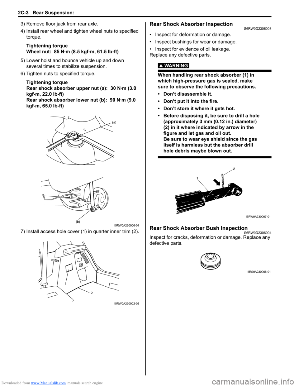
Rear shock absorber upper nut (a): 30 N·m (3.0
kgf-m, 22.0 lb-ft)
Rear shock absorber lower nut (b): 90 N·m (9.0
kgf-m, 65.0 lb-ft)
7) Install access hole cover (1) in quarter inner trim (2).Rear Shock Absorber InspectionS6RW0D2306003
• Inspect for deformation or damage.
• Inspect bushings for wear or damage.
• Inspect for evidence of oil leakage.
Replace any defective parts.
WARNING!
When handling rear shock absorber (1) in
which high-pressure gas is sealed, make
sure to observe the following precautions.
• Don’t disassemble it.
• Don’t put it into the fire.
• Don’t store it where it gets hot.
• Before disposing it, be sure to drill a hole
(approximately 3 mm (0.12 in.) diameter)
(2) in it where indicated by arrow in the
figure and let gas and oil out.
Be sure to wear eye shield since the gas
itself is harmless but the absorber drill
hole debris maybe blown out.
Rear Shock Absorber Bush InspectionS6RW0D2306004
Inspect for cracks, deformation or damage. Replace any
defective parts.
(a)
(b)I5RW0A230006-01
2
1
I5RW0A230002-02
I5RW0A230007-01
I4RS0A230008-01
Page 1032 of 1556
Downloaded from www.Manualslib.com manuals search engine 8A-1 Seat Belts:
Restraint
Seat Belts
Precautions
Precautions on Service and Diagnosis of Seat BeltS6RW0D8100001
WARNING!
If replacing seat belt is necessary, replace buckle and seat belt together as a set. This is for the reason
of ensuring locking of tongue plate with buckle. If these parts are replaced individually, such a locking
condition may become unreliable. For this reason, SUZUKI will supply only the spare buckle and seat
belt assembly in a set part.
Before servicing or replacing seat belts, refer to the following precautionary items.
• Seat belts should be normal relative to strap retractor and buckle portions.
• Keep sharp edges and damaging objects away from belts.
• Avoid bending or damaging any portion of belt buckle or latch plate.
• Do not bleach or dye belt webbing. (Use only mild soap and lukewarm water to clean it.)
• When installing a seat belt anchor bolt, it should be tightened by hand at first to prevent cross-threading and then to
specified torque.
• Do not attempt any repairs on retractor mechanisms or retractor covers. Replace defective assemblies with new
replacement parts.
• Keep belts dry and clean at all times.
• If there exist any parts in question, replace such parts.
• Replace belts whose webbing is cut or otherwise damaged.
• Do not put anything into trim panel opening which seat belt webbing passes through.
Page 1036 of 1556
Downloaded from www.Manualslib.com manuals search engine 8A-5 Seat Belts:
Front Seat Belt Removal and InstallationS6RW0D8106002
WARNING!
• Never attempt to disassemble or repair the
retractor (seat belt pretensioner). If any
abnormality is found, be sure to replace it
with new one as an assembly.
• Be sure to read “Precautions on Service
and Diagnosis of Seat Belt” before starting
to work and observe every precaution
during work. Neglecting them may result in
personal injury or unactivation of the seat
belt pretensioner when necessary.
Removal
1) Disconnect negative (–) cable at battery.
2) Disable air bag system. Refer to “Disabling Air Bag
System in Section 8B”.
3) Remove center pillar lower trim.
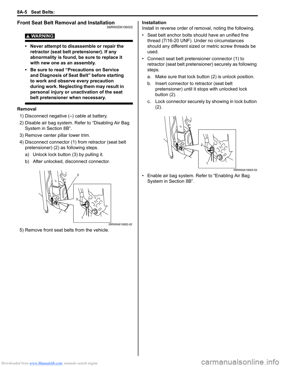
4) Disconnect connector (1) from retractor (seat belt
pretensioner) (2) as following steps.
a) Unlock lock button (3) by pulling it.
b) After unlocked, disconnect connector.
5) Remove front seat belts from the vehicle.Installation
Install in reverse order of removal, noting the following.
• Seat belt anchor bolts should have an unified fine
thread (7/16-20 UNF). Under no circumstances
should any different sized or metric screw threads be
used.
• Connect seat belt pretensioner connector (1) to
retractor (seat belt pretensioner) securely as following
steps.
a. Make sure that lock button (2) is unlock position.
b. Insert connector to retractor (seat belt
pretensioner) until it stops with unlocked lock
button (2).
c. Lock connector securely by showing in lock button
(2).
• Enable air bag system. Refer to “Enabling Air Bag
System in Section 8B”.
2
1
3
I5RW0A810002-02
1
2
I5RW0A810003-03
Page 1039 of 1556
Downloaded from www.Manualslib.com manuals search engine Seat Belts: 8A-8
Rear Seat Belt Removal and InstallationS6RW0D8106005
WARNING!
Be sure to read “Precautions on Service and
Diagnosis of Seat Belt” before starting to
work and observe every precaution during
work.
Removal
1) Fold rear seats referring to “Folding Rear Seats” in
Owners Manual.
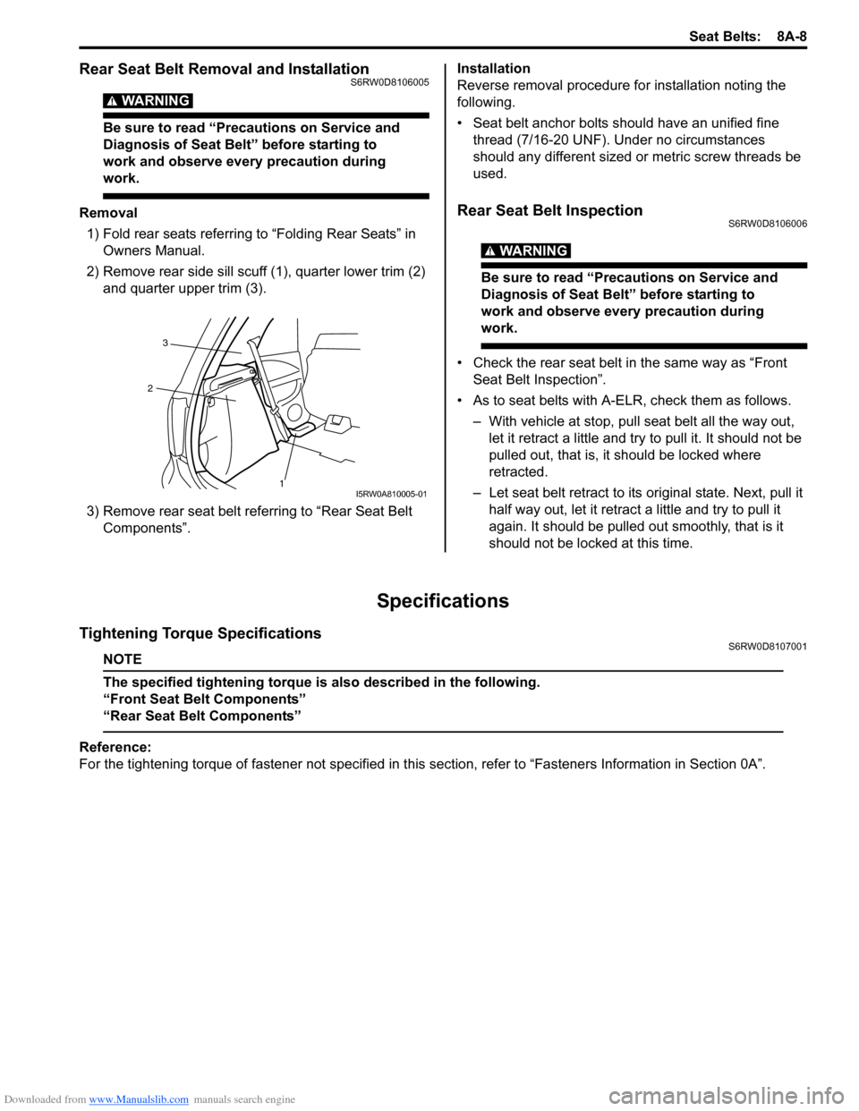
2) Remove rear side sill scuff (1), quarter lower trim (2)
and quarter upper trim (3).
3) Remove rear seat belt referring to “Rear Seat Belt
Components”.Installation
Reverse removal procedure for installation noting the
following.
• Seat belt anchor bolts should have an unified fine
thread (7/16-20 UNF). Under no circumstances
should any different sized or metric screw threads be
used.Rear Seat Belt InspectionS6RW0D8106006
WARNING!
Be sure to read “Precautions on Service and
Diagnosis of Seat Belt” before starting to
work and observe every precaution during
work.
• Check the rear seat belt in the same way as “Front
Seat Belt Inspection”.
• As to seat belts with A-ELR, check them as follows.
– With vehicle at stop, pull seat belt all the way out,
let it retract a little and try to pull it. It should not be
pulled out, that is, it should be locked where
retracted.
– Let seat belt retract to its original state. Next, pull it
half way out, let it retract a little and try to pull it
again. It should be pulled out smoothly, that is it
should not be locked at this time.
Specifications
Tightening Torque SpecificationsS6RW0D8107001
NOTE
The specified tightening torque is also described in the following.
“Front Seat Belt Components”
“Rear Seat Belt Components”
Reference:
For the tightening torque of fastener not specified in this section, refer to “Fasteners Information in Section 0A”.
1 23I5RW0A810005-01
Page 1042 of 1556
Downloaded from www.Manualslib.com manuals search engine 8B-3 Air Bag System:
WARNING!
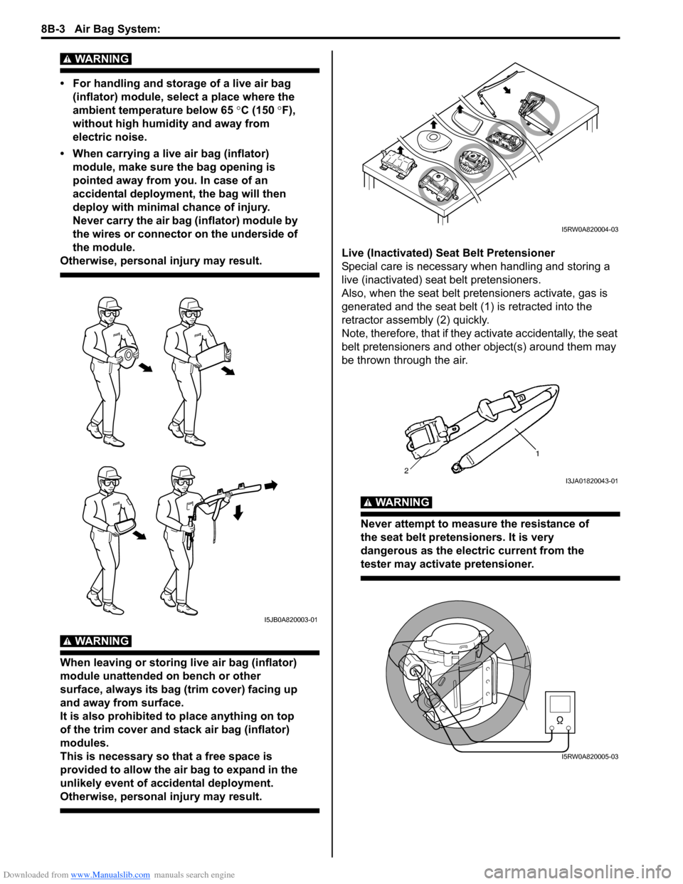
• For handling and storage of a live air bag
(inflator) module, select a place where the
ambient temperature below 65 °C (150 °F),
without high humidity and away from
electric noise.
• When carrying a live air bag (inflator)
module, make sure the bag opening is
pointed away from you. In case of an
accidental deployment, the bag will then
deploy with minimal chance of injury.
Never carry the air bag (inflator) module by
the wires or connector on the underside of
the module.
Otherwise, personal injury may result.
WARNING!
When leaving or storing live air bag (inflator)
module unattended on bench or other
surface, always its bag (trim cover) facing up
and away from surface.
It is also prohibited to place anything on top
of the trim cover and stack air bag (inflator)
modules.
This is necessary so that a free space is
provided to allow the air bag to expand in the
unlikely event of accidental deployment.
Otherwise, personal injury may result.
Live (Inactivated) Seat Belt Pretensioner
Special care is necessary when handling and storing a
live (inactivated) seat belt pretensioners.
Also, when the seat belt pretensioners activate, gas is
generated and the seat belt (1) is retracted into the
retractor assembly (2) quickly.
Note, therefore, that if they activate accidentally, the seat
belt pretensioners and other object(s) around them may
be thrown through the air.
WARNING!
Never attempt to measure the resistance of
the seat belt pretensioners. It is very
dangerous as the electric current from the
tester may activate pretensioner.
I5JB0A820003-01
I5RW0A820004-03
I3JA01820043-01
I5RW0A820005-03
Page 1072 of 1556
Downloaded from www.Manualslib.com manuals search engine 8B-33 Air Bag System:
NOTE
Upon completion of inspection and repair work, perform the following items.
• Reconnect all air bag system components and ensure all components are properly mounted.
• Clear DTCs referring to “DTC Clearance”, if any.
• Repeat “Air Bag Diagnostic System Check” to confirm that the trouble has been corrected.
DTC B1032: Driver Air Bag Circuit Low ResistanceS6RW0D8204019
Wiring Diagram
Refer to “DTC B1031: Driver Air Bag Circuit High Resistance”.
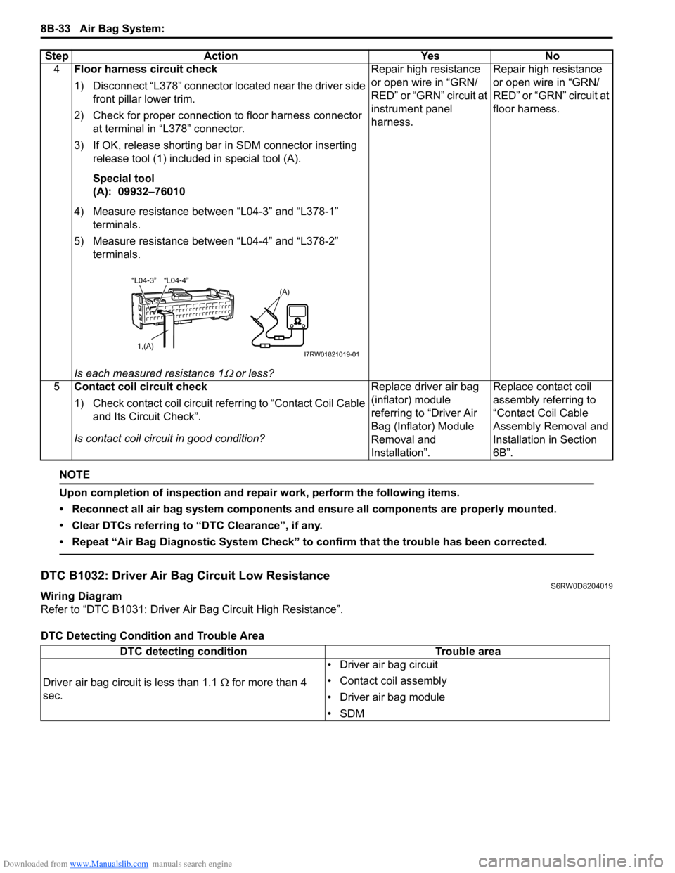
DTC Detecting Condition and Trouble Area4Floor harness circuit check
1) Disconnect “L378” connector located near the driver side
front pillar lower trim.
2) Check for proper connection to floor harness connector
at terminal in “L378” connector.
3) If OK, release shorting bar in SDM connector inserting
release tool (1) included in special tool (A).
Special tool
(A): 09932–76010
4) Measure resistance between “L04-3” and “L378-1”
terminals.
5) Measure resistance between “L04-4” and “L378-2”
terminals.
Is each measured resistance 1
Ω or less?Repair high resistance
or open wire in “GRN/
RED” or “GRN” circuit at
instrument panel
harness.Repair high resistance
or open wire in “GRN/
RED” or “GRN” circuit at
floor harness.
5Contact coil circuit check
1) Check contact coil circuit referring to “Contact Coil Cable
and Its Circuit Check”.
Is contact coil circuit in good condition?Replace driver air bag
(inflator) module
referring to “Driver Air
Bag (Inflator) Module
Removal and
Installation”.Replace contact coil
assembly referring to
“Contact Coil Cable
Assembly Removal and
Installation in Section
6B”. Step Action Yes No
“L04-4” “L04-3”
1,(A)
(A)
I7RW01821019-01
DTC detecting condition Trouble area
Driver air bag circuit is less than 1.1 Ω for more than 4
sec.• Driver air bag circuit
• Contact coil assembly
• Driver air bag module
•SDM
Page 1074 of 1556
Downloaded from www.Manualslib.com manuals search engine 8B-35 Air Bag System:
NOTE
Upon completion of inspection and repair work, perform the following items.
• Reconnect all air bag system components and ensure all components are properly mounted.
• Clear DTCs referring to “DTC Clearance”, if any.
• Repeat “Air Bag Diagnostic System Check” to confirm that the trouble has been corrected.
DTC B1033: Driver Air Bag Circuit Shorted to GroundS6RW0D8204020
Wiring Diagram
Refer to “DTC B1031: Driver Air Bag Circuit High Resistance”.
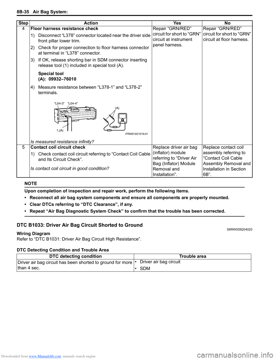
DTC Detecting Condition and Trouble Area4Floor harness resistance check
1) Disconnect “L378” connector located near the driver side
front pillar lower trim.
2) Check for proper connection to floor harness connector
at terminal in “L378” connector.
3) If OK, release shorting bar in SDM connector inserting
release tool (1) included in special tool (A).
Special tool
(A): 09932–76010
4) Measure resistance between “L378-1” and “L378-2”
terminals.
Is measured resistance infinity?Repair “GRN/RED”
circuit for short to “GRN”
circuit at instrument
panel harness.Repair “GRN/RED”
circuit for short to “GRN”
circuit at floor harness.
5Contact coil circuit check
1) Check contact coil circuit referring to “Contact Coil Cable
and Its Circuit Check”.
Is contact coil circuit in good condition?Replace driver air bag
(inflator) module
referring to “Driver Air
Bag (Inflator) Module
Removal and
Installation”.Replace contact coil
assembly referring to
“Contact Coil Cable
Assembly Removal and
Installation in Section
6B”. Step Action Yes No
“L04-4” “L04-3”
1,(A)
(A)
I7RW01821019-01
DTC detecting condition Trouble area
Driver air bag circuit has been shorted to ground for more
than 4 sec.• Driver air bag circuit
•SDM
Page 1075 of 1556

Downloaded from www.Manualslib.com manuals search engine Air Bag System: 8B-36
DTC Troubleshooting
Step Action Yes No
1Was “Air Bag Diagnostic System Check Flow” performed?Go to Step 2. Go to “Air Bag
Diagnostic System
Check Flow”.
2Driver air bag circuit check
1) With ignition switch turned OFF, disconnect contact coil
connector “G347” located under the steering column.
2) Disconnect SDM connector “L04”.
3) Check for proper connection to flow harness connector
at terminal in “G347” connector.
4) Check for proper connection to SDM connector at
terminal “L04-3” and “L04-4”.
5) If OK, release shorting bar in SDM connector inserting
release tool (1) included in special tool (A).
Special tool
(A): 09932–76010
6) Measure resistance between “G347-1” terminal and
body ground, and between “G347-2” terminal and body
ground.
Is each measured resistance infinity?Go to Step 4. Go to Step 3.
3Floor harness circuit check
1) Disconnect “L378” connector located near the driver side
front pillar lower trim.
2) If OK, release shorting bar in SDM connector inserting
release tool (1) included in special tool (A).
Special tool
(A): 09932–76010
3) Measure resistance between “L378-1” terminal and body
ground, and between “L378-2” terminal and body
ground.
Is each measured resistance infinity?Repair “GRN/RED”
circuit or “GRN” circuit
for short to ground at
instrument panel
harness.Repair “GRN/RED”
circuit or “GRN” circuit
for short to ground at
floor harness.
“L04-4” “L04-3”
1,(A)
(A)
I7RW01821020-01
“L04-4” “L04-3”
1,(A)
(A)
I7RW01821020-01
Page 1077 of 1556

Downloaded from www.Manualslib.com manuals search engine Air Bag System: 8B-38
DTC Troubleshooting
Step Action Yes No
1Was “Air Bag Diagnostic System Check Flow” performed?Go to Step 2. Go to “Air Bag
Diagnostic System
Check Flow”.
2Driver air bag circuit check
1) With ignition switch turned OFF, disconnect contact coil
connector “G347” located under the steering column.
2) Disconnect SDM connector “L04”.
3) Check for proper connection to contact coil connector at
terminal in “G347” connector.
4) Check for proper connection to SDM connector at
terminal “L04-3” and “L04-4”.
5) If OK, release shorting bar in SDM connector inserting
release tool (1) included in special tool (A).
Special tool
(A): 09932–76010
6) With ignition switch turned ON, measure voltage
between “G347-1” terminal and body ground, and
between “G347-2” terminal and body ground.
Is each measured voltage 0 V?Go to Step 4. Go to Step 3.
3Floor harness circuit check
1) Disconnect “L378” connector located near the driver side
front pillar lower trim.
2) If OK, release shorting bar in SDM connector inserting
release tool (1) included in special tool (A).
Special tool
(A): 09932–76010
3) With ignition switch turned ON, measure voltage
between “L378-1” terminal and body ground, and
between “L378-2” terminal and body ground.
Is each measured voltage 0 V?Repair “GRN/RED”
circuit or “GRN” circuit
for short to power
supply circuit at
instrument panel
harness.Repair “GRN/RED”
circuit or “GRN” circuit
for short to power
supply circuit at floor
harness.
“L04-4” “L04-3”
1,(A)
(A)
I7RW01821022-01
“L04-4” “L04-3”
1,(A)
(A)
I7RW01821022-01
Page 1081 of 1556

Downloaded from www.Manualslib.com manuals search engine Air Bag System: 8B-42
NOTE
Upon completion of inspection and repair work, perform the following items.
• Reconnect all air bag system components and ensure all components are properly mounted.
• Clear DTCs referring to “DTC Clearance”, if any.
• Repeat “Air Bag Diagnostic System Check” to confirm that the trouble has been corrected.
3Passenger air bag circuit check
1) With ignition switch turned OFF, disconnect SDM
connector “L04”.
2) Check for proper connection to SDM connector at
terminal “L04-5” and “L04-6”.
3) If OK, release shorting bar in SDM connector by
inserting release tool (1) included in special tool (A).
Special tool
(A): 09932–76010
4) Measure resistance between “L04-5” and “G259-1”
terminals.
5) Measure resistance between “L04-6” and “G259-2”
terminals.
Is each measured resistance 1
Ω or less?Substitute a known-
good SDM and recheck.Go to Step 4.
4Floor harness circuit check
1) Disconnect “L377” connector located near the
passenger side front pillar lower trim.
2) Check for proper connection to floor harness connector
at terminal in “L377” connector.
3) If OK, release shorting bar in SDM connector by
inserting release tool (1) included in special tool (A).
Special tool
(A): 09932–76010
4) Measure resistance between “L04-5” and “L377-2”
terminals.
5) Measure resistance between “L04-6” and “L377-1”
terminals.
Is each measured resistance 1
Ω or less?Repair high resistance
or open wire in “BLU/
RED” or “YEL/RED”
circuit at instrument
panel harness.Repair high resistance
or open wire in “BLU/
RED” or “YEL/RED”
circuit at floor harness. Step Action Yes No
“L04-5”“L04-6”
1, (A)
(A)
I7RW01821026-01
“L04-5”“L04-6”
1, (A)
(A)
I7RW01821026-01