engine mount SUZUKI SX4 2006 1.G Service Workshop Manual
[x] Cancel search | Manufacturer: SUZUKI, Model Year: 2006, Model line: SX4, Model: SUZUKI SX4 2006 1.GPages: 1556, PDF Size: 37.31 MB
Page 1449 of 1556
Downloaded from www.Manualslib.com manuals search engine Body Structure: 9K-5
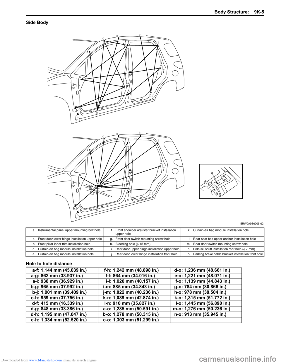
Side Body
Hole to hole distance
o
dek
fl
im
n
g
j
h
o
ac
b
dek
fl
im
n
g
j
h
ac
b
I5RW0A9B0005-02
a. Instrumental panel upper mounting bolt hole f. Front shoulder adjuster bracket installation
upper holek. Curtain-air bag module installation hole
b. Front door lower hinge installation upper hole g. Front door switch mounting screw hole l. Rear seat belt upper anchor installation hole
c. Front pillar inner trim installation hole h. Bleeding hole (φ 15 mm) m. Rear door switch mounting screw hole
d. Curtain-air bag module installation hole i. Rear door upper hinge installation upper hole n. Side sill scuff installation rear hole (φ 7 mm)
e. Curtain-air bag module installation hole j. Rear door lower hinge installation front hole o. Parking brake cable bracket installation front hole
a-f: 1,144 mm (45.039 in.) f-h: 1,242 mm (48.898 in.) d-o: 1,236 mm (48.661 in.)
a-g: 862 mm (33.937 in.) f-l: 864 mm (34.016 in.) e-o: 1,221 mm (48.071 in.)
a-i: 938 mm (36.929 in.) i-l: 1,020 mm (40.157 in.) f-o: 1,139 mm (44.843 in.)
b-g: 965 mm (37.992 in.) i-m: 885 mm (34.843 in.) g-o: 784 mm (30.866 in.)
b-j: 1,001 mm (39.409 in.) j-m: 1,022 mm (40.236 in.) h-o: 978 mm (38.504 in.)
c-h: 959 mm (37.756 in.) k-n: 1,089 mm (42.874 in.) k-o: 1,315 mm (51.772 in.)
d-f: 415 mm (16.339 in.) l-n: 910 mm (35.827 in.) l-o: 1,445 mm (56.890 in.)
d-g: 848 mm (33.386 in.) a-o: 1,285 mm (50.591 in.) m-o: 1,276 mm (50.236 in.)
d-h: 1,195 mm (47.047 in.) b-o: 1,278 mm (50.315 in.) n-o: 913 mm (35.945 in.)
e-h: 1,334 mm (52.520 in.) c-o: 1,303 mm (51.299 in.)
Page 1453 of 1556
Downloaded from www.Manualslib.com manuals search engine Body Structure: 9K-9
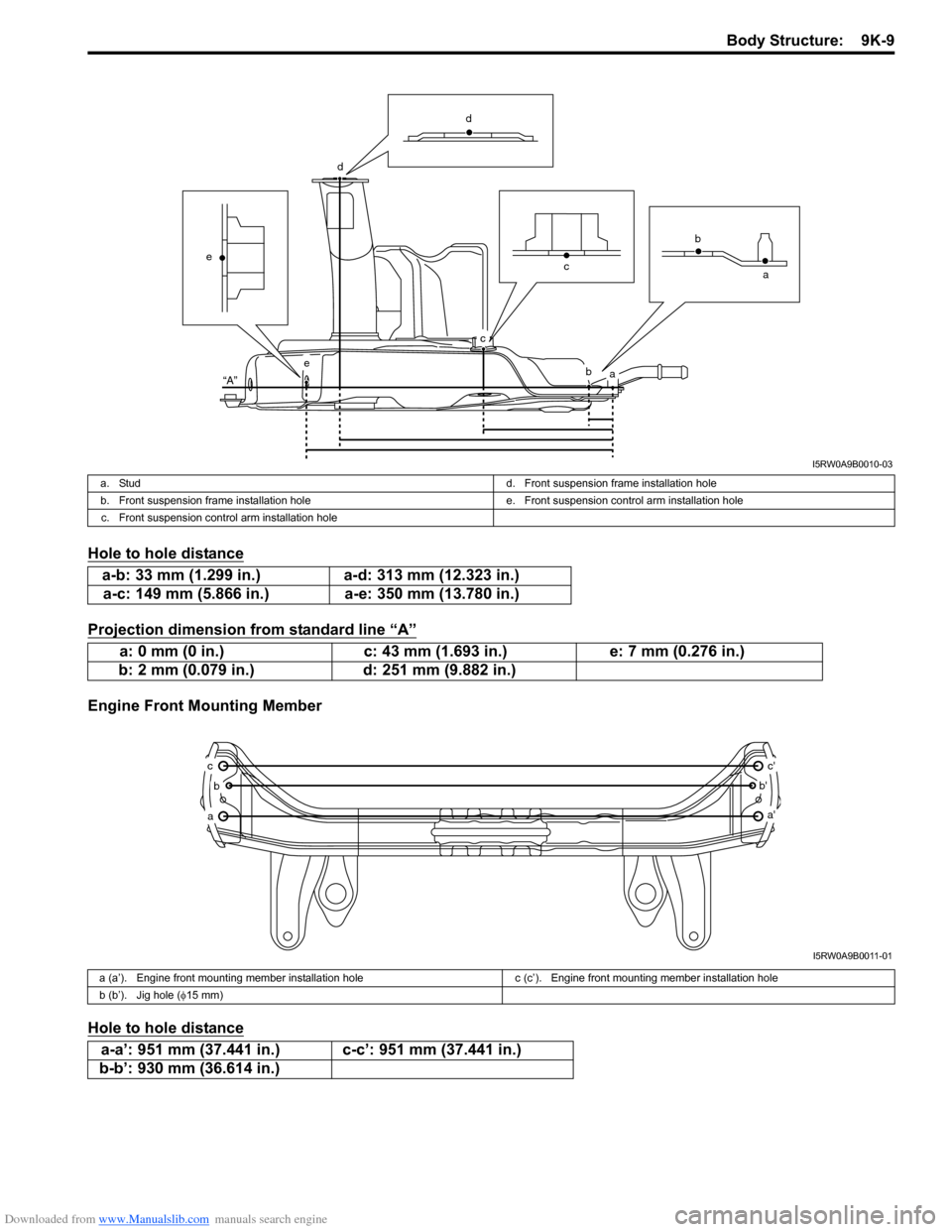
Hole to hole distance
Projection dimension from standard line “A”
Engine Front Mounting Member
Hole to hole distance
ab
c
d
e
“A”
e
d
ca b
I5RW0A9B0010-03
a. Studd. Front suspension frame installation hole
b. Front suspension frame installation hole e. Front suspension control arm installation hole
c. Front suspension control arm installation hole
a-b: 33 mm (1.299 in.) a-d: 313 mm (12.323 in.)
a-c: 149 mm (5.866 in.) a-e: 350 mm (13.780 in.)
a: 0 mm (0 in.) c: 43 mm (1.693 in.) e: 7 mm (0.276 in.)
b: 2 mm (0.079 in.) d: 251 mm (9.882 in.)
a
b
c
a'
b'
c'
I5RW0A9B0011-01
a (a’). Engine front mounting member installation hole c (c’). Engine front mounting member installation hole
b (b’). Jig hole (φ15 mm)
a-a’: 951 mm (37.441 in.) c-c’: 951 mm (37.441 in.)
b-b’: 930 mm (36.614 in.)
Page 1455 of 1556
Downloaded from www.Manualslib.com manuals search engine Paint / Coatings: 9L-1
Body, Cab and Accessories
Paint / Coatings
General Description
Anti-Corrosion Treatment ConstructionS6RW0D9C01001
WARNING!
Standard shop practices, particularly eye protection, should be followed during the performance of the
following operations to avoid personal injury.
As rust proof treatment, steel sheets are given corrosion resistance on the interior and/or exterior.
These corrosion resistance steel sheet materials are called one of two-side galvanized steel sheets.
It is for the sake of rust protection that these materials are selected and given a variety of treatments as described
blow.
• Steel sheets are treated with cathodic electro primer which is excellent in corrosion resistance.
• Rust proof wax coatings are applied to door and side sill insides where moisture is liable to stay.
• Vinyl coating is applied to body underside and wheel housing inside.
• Sealer is applied to door hem, engine compartment steel sheet-to-steel sheet joint, and the like portions to prevent
water penetration and resulting in rust occurrence.
In panel replacement or collision damage repair, leaving the relevant area untreated as it is in any operation which
does disturb the rust proof treatment will cause corrosion to that area. Therefore, it is the essential function of any
repair operation to correctly recoat the related surfaces of the relevant area.
All the metal panels are coated with metal conditioners and primer coating during vehicle production. Following the
repair and/or replacement parts installation, every accessible bare metal surface should be cleaned and coated with
rust proof primer. Perform this operation prior to the application of sealer and rust proof wax coating.
Sealer is applied to the specific joints of a vehicle during production. The sealer is intended to prevent dust from
entering the vehicle and serves also as an anticorrosion barrier. The sealer is applied to the door and hood hem areas
and between panels. Correct and reseal the originally sealed joints if damaged. Reseal the attaching joints of a new
replacement panel and reseal the hem area of a replacement door or hood.
Use a quality sealer to seal the flanged joints, overlap joints and seams. The sealer must have flexible characteristics
and paint ability after it’s applied to repair areas.
For the sealer to fill open joints, use caulking material. Select a sealer in conformance with the place and purpose of a
specific use. Observe the manufacturer’s label-stand instructions when using the sealer.
In many cases, repaired places require color painting. When this is required, follow the ordinary techniques specified
for the finish preparation, color painting and undercoating build-up.
Rust proof wax, a penetrative compound, is applied to the metal-to-metal surfaces (door and side sill insides) where it
is difficult to use ordinary undercoating material for coating. Therefore, when selecting the rust proof wax, it may be the
penetrative type.
During the undercoating (vinyl coating) application, care should be taken that sealer is not applied to the engine-
related parts and shock absorber mounting or rotating parts. Following the under coating, make sure that body drain
holes are kept open.
The sequence of the application steps of the anti-corrosion materials are as follows:
1) Clean and prepare the metal surface.
2) Apply primer.
3) Apply sealer (all joints sealed originally).
4) Apply color in areas where color is required such as hem flanges, exposed joints and under body components.
5) Apply anticorrosion compound (penetrative wax).
6) Apply undercoating (rust proof material).
Page 1501 of 1556
Downloaded from www.Manualslib.com manuals search engine Body Electrical Control System: 10B-28
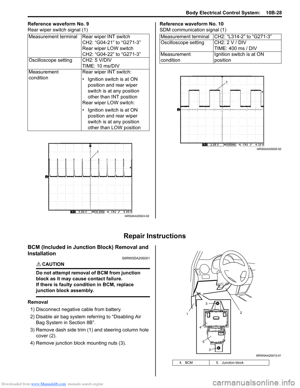
Reference waveform No. 9
Rear wiper switch signal (1)Reference waveform No. 10
SDM communication signal (1)
Repair Instructions
BCM (Included in Junction Block) Removal and
Installation
S6RW0DA206001
CAUTION!
Do not attempt removal of BCM from junction
block as it may cause contact failure.
If there is faulty condition in BCM, replace
junction block assembly.
Removal
1) Disconnect negative cable from battery.
2) Disable air bag system referring to “Disabling Air
Bag System in Section 8B”.
3) Remove dash side trim (1) and steering column hole
cover (2).
4) Remove junction block mounting nuts (3). Measurement terminal Rear wiper INT switch
CH2: “G04-21” to “G271-3”
Rear wiper LOW switch
CH2: “G04-22” to “G271-3”
Oscilloscope setting CH2: 5 V/DIV
TIME: 10 ms/DIV
Measurement
conditionRear wiper INT switch:
• Ignition switch is at ON
position and rear wiper
switch is at any position
other than INT position
Rear wiper LOW switch:
• Ignition switch is at ON
position and rear wiper
switch is at any position
other than LOW position
I4RS0AA20024-02
Measurement terminal CH2: “L314-2” to “G271-3”
Oscilloscope setting CH2: 2 V / DIV
TIME: 400 ms / DIV
Measurement
conditionIgnition switch is at ON
position
I4RS0AA20026-02
4. BCM 5. Junction block
2
1
3
3
4
5
I5RW0AA20015-01
Page 1551 of 1556
Downloaded from www.Manualslib.com manuals search engine Keyless Start System: 10E-29
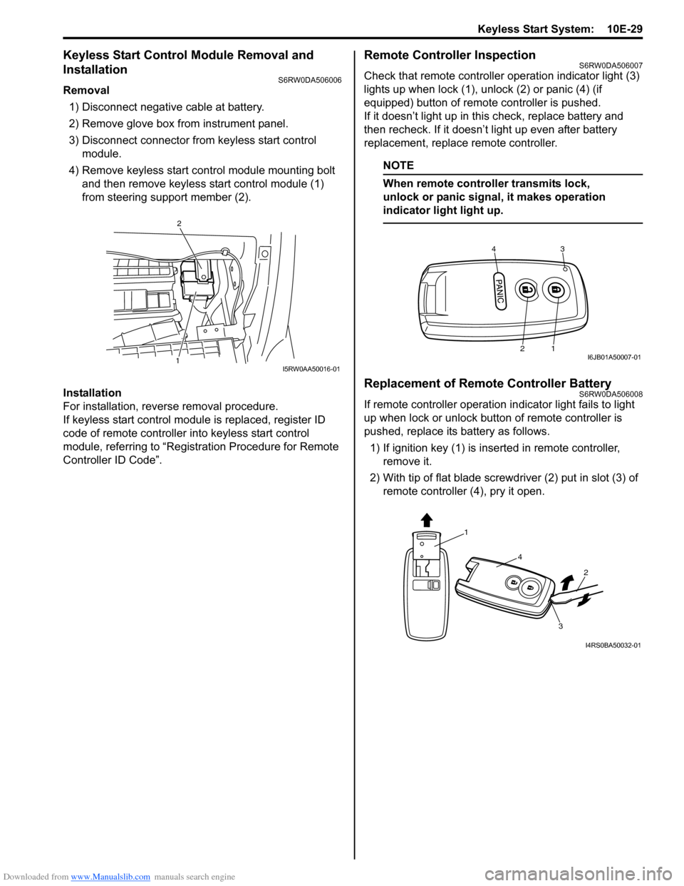
Keyless Start Control Module Removal and
Installation
S6RW0DA506006
Removal
1) Disconnect negative cable at battery.
2) Remove glove box from instrument panel.
3) Disconnect connector from keyless start control
module.
4) Remove keyless start control module mounting bolt
and then remove keyless start control module (1)
from steering support member (2).
Installation
For installation, reverse removal procedure.
If keyless start control module is replaced, register ID
code of remote controller into keyless start control
module, referring to “Registration Procedure for Remote
Controller ID Code”.
Remote Controller InspectionS6RW0DA506007
Check that remote controller operation indicator light (3)
lights up when lock (1), unlock (2) or panic (4) (if
equipped) button of remote controller is pushed.
If it doesn’t light up in this check, replace battery and
then recheck. If it doesn’t light up even after battery
replacement, replace remote controller.
NOTE
When remote controller transmits lock,
unlock or panic signal, it makes operation
indicator light light up.
Replacement of Remote Controller BatteryS6RW0DA506008
If remote controller operation indicator light fails to light
up when lock or unlock button of remote controller is
pushed, replace its battery as follows.
1) If ignition key (1) is inserted in remote controller,
remove it.
2) With tip of flat blade screwdriver (2) put in slot (3) of
remote controller (4), pry it open.
1
2
I5RW0AA50016-01
43
21I6JB01A50007-01
1
4
2
3
I4RS0BA50032-01