Rear sensor SUZUKI SX4 2006 1.G Service Owner's Manual
[x] Cancel search | Manufacturer: SUZUKI, Model Year: 2006, Model line: SX4, Model: SUZUKI SX4 2006 1.GPages: 1556, PDF Size: 37.31 MB
Page 528 of 1556
Downloaded from www.Manualslib.com manuals search engine 3B-31 Differential:
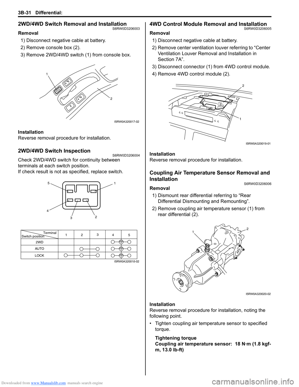
2WD/4WD Switch Removal and InstallationS6RW0D3206003
Removal
1) Disconnect negative cable at battery.
2) Remove console box (2).
3) Remove 2WD/4WD switch (1) from console box.
Installation
Reverse removal procedure for installation.
2WD/4WD Switch InspectionS6RW0D3206004
Check 2WD/4WD switch for continuity between
terminals at each switch position.
If check result is not as specified, replace switch.
4WD Control Module Removal and InstallationS6RW0D3206005
Removal
1) Disconnect negative cable at battery.
2) Remove center ventilation louver referring to “Center
Ventilation Louver Removal and Installation in
Section 7A”.
3) Disconnect connector (1) from 4WD control module.
4) Remove 4WD control module (2).
Installation
Reverse removal procedure for installation.
Coupling Air Temperature Sensor Removal and
Installation
S6RW0D3206006
Removal
1) Dismount rear differential referring to “Rear
Differential Dismounting and Remounting”.
2) Remove coupling air temperature sensor (1) from
rear differential (2).
Installation
Reverse removal procedure for installation, noting the
following point.
• Tighten coupling air temperature sensor to specified
torque.
Tightening torque
Coupling air temperature sensor: 18 N·m (1.8 kgf-
m, 13.0 lb-ft)
1
2
I5RW0A320017-02
Terminal
Switch position
2WD
AUTO
LOCK
11
22
3 3
4 4
5 5
I5RW0A320018-02
2
1
I5RW0A320019-01
12
I5RW0A320020-02
Page 532 of 1556
Downloaded from www.Manualslib.com manuals search engine 3B-35 Differential:
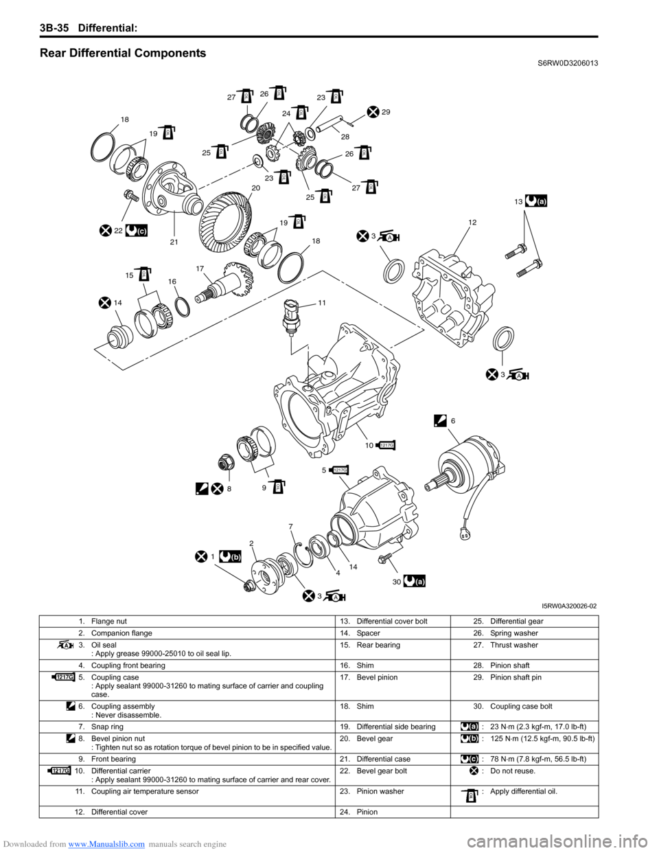
Rear Differential ComponentsS6RW0D3206013
4 5
9
2
30
6
(a)13
12
(a)
3
A
3A
141617 2118
29
3A
1(b)
22
1217G
101217G
11
8OIL
15OIL
19 20OIL
23OIL
25OIL27OIL
27OIL
25OIL
19OIL18
26 28
OIL
26OIL23OIL
24OIL
(c)
14
7
I5RW0A320026-02
1. Flange nut 13. Differential cover bolt 25. Differential gear
2. Companion flange 14. Spacer 26. Spring washer
3. Oil seal
: Apply grease 99000-25010 to oil seal lip.15. Rear bearing 27. Thrust washer
4. Coupling front bearing 16. Shim 28. Pinion shaft
5. Coupling case
: Apply sealant 99000-31260 to mating surface of carrier and coupling
case.17. Bevel pinion 29. Pinion shaft pin
6. Coupling assembly
: Never disassemble.18. Shim 30. Coupling case bolt
7. Snap ring 19. Differential side bearing : 23 N⋅m (2.3 kgf-m, 17.0 lb-ft)
8. Bevel pinion nut
: Tighten nut so as rotation torque of bevel pinion to be in specified value.20. Bevel gear : 125 N⋅m (12.5 kgf-m, 90.5 lb-ft)
9. Front bearing 21. Differential case : 78 N⋅m (7.8 kgf-m, 56.5 lb-ft)
10. Differential carrier
: Apply sealant 99000-31260 to mating surface of carrier and rear cover.22. Bevel gear bolt : Do not reuse.
11. Coupling air temperature sensor 23. Pinion washer : Apply differential oil.
12. Differential cover 24. Pinion
Page 545 of 1556
Downloaded from www.Manualslib.com manuals search engine Differential: 3B-48
Specifications
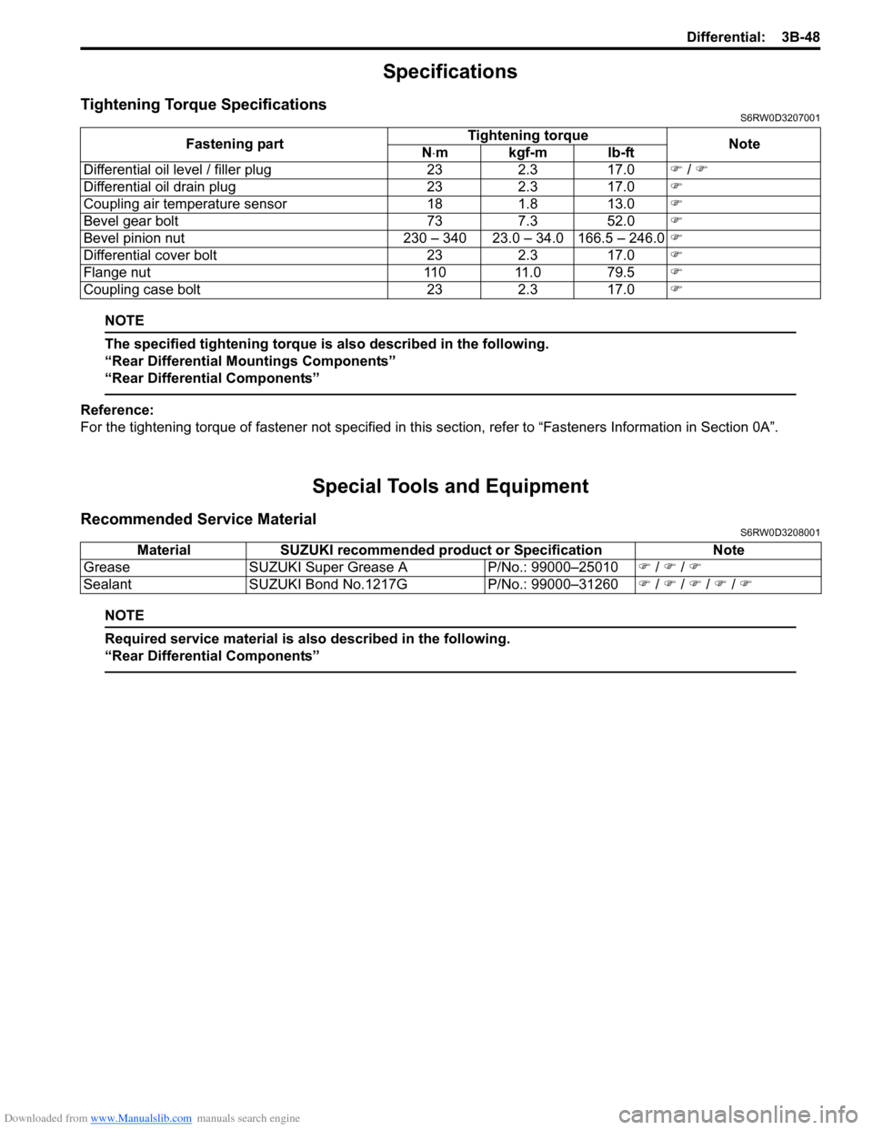
Tightening Torque SpecificationsS6RW0D3207001
NOTE
The specified tightening torque is also described in the following.
“Rear Differential Mountings Components”
“Rear Differential Components”
Reference:
For the tightening torque of fastener not specified in this section, refer to “Fasteners Information in Section 0A”.
Special Tools and Equipment
Recommended Service MaterialS6RW0D3208001
NOTE
Required service material is also described in the following.
“Rear Differential Components”
Fastening partTightening torque
Note
N⋅mkgf-mlb-ft
Differential oil level / filler plug 23 2.3 17.0�) / �)
Differential oil drain plug 23 2.3 17.0�)
Coupling air temperature sensor 18 1.8 13.0�)
Bevel gear bolt 73 7.3 52.0�)
Bevel pinion nut 230 – 340 23.0 – 34.0 166.5 – 246.0�)
Differential cover bolt 23 2.3 17.0�)
Flange nut 110 11.0 79.5�)
Coupling case bolt 23 2.3 17.0�)
Material SUZUKI recommended product or Specification Note
Grease SUZUKI Super Grease A P/No.: 99000–25010�) / �) / �)
Sealant SUZUKI Bond No.1217G P/No.: 99000–31260�) / �) / �) / �) / �)
Page 570 of 1556
Downloaded from www.Manualslib.com manuals search engine 4-ii Table of Contents
Specifications .......................................................4D-4
Tightening Torque Specifications ........................4D-4
ABS ............................................................4E-1
Precautions........................................................... 4E-1
Precautions in Diagnosing Troubles ................... 4E-1
Precautions in On-Vehicle Service...................... 4E-1
General Description ............................................. 4E-2
ABS Description .................................................. 4E-2
ABS Hydraulic Unit / Control Module
Assembly Description ....................................... 4E-3
CAN Communication System Description........... 4E-3
Schematic and Routing Diagram ........................ 4E-4
ABS Schematic ................................................... 4E-4
ABS Wiring Circuit Diagram ................................ 4E-5
Component Location ........................................... 4E-8
ABS Components Location ................................. 4E-8
Diagnostic Information and Procedures ............ 4E-8
ABS Check .......................................................... 4E-8
ABS Warning Light Check................................. 4E-10
EBD Warning Light (Brake Warning Light)
Check .............................................................. 4E-10
DTC Check........................................................ 4E-11
DTC Table ......................................................... 4E-11
DTC Clearance ................................................. 4E-11
Scan Tool Data ................................................. 4E-12
ABS Warning Light Does Not Come ON at
Ignition Switch ON .......................................... 4E-13
ABS Warning Light Comes ON Steady ............. 4E-15
EBD Warning Light (Brake Warning Light)
Comes ON Steady .......................................... 4E-16
Serial Data Link Circuit Check .......................... 4E-17
DTC C1013: Control Module Mismatch ............ 4E-20
DTC C1015: G Sensor Circuit (4WD Model)..... 4E-21
DTC 1016: Brake Light Switch .......................... 4E-22
DTC C1021 / C1022 / C1025 / C1026 / C1031
/ C1032 / C1035 / C1036: Wheel Speed
Sensor Circuit / Sensor or Encoder ................ 4E-23
DTC C1033: Wheel Speed Sensor Deviation ... 4E-25
DTC C1041 / C1042 / C1045 / C1046 / C1051
/ C1052 / C1055 / C1056: Inlet / Outlet
Solenoid .......................................................... 4E-26DTC C1057: Power Supply Voltage Too High
/ Too Low ........................................................ 4E-27
DTC C1061: Pump Motor Circuit ...................... 4E-28
DTC C1063: Solenoid Valve Power Supply
Driver Circuit ................................................... 4E-29
DTC C1071: Control Module Internal Defect .... 4E-30
ABS Hydraulic Unit / Control Module
Assembly Power and Ground Circuit Check ... 4E-30
Repair Instructions ............................................ 4E-31
ABS Hydraulic Unit Operation Check................ 4E-31
ABS Hydraulic Unit / Control Module
Assembly Components ................................... 4E-32
ABS Hydraulic Unit / Control Module
Assembly On-Vehicle Inspection .................... 4E-33
ABS Hydraulic Unit / Control Module
Assembly Removal and Installation ................ 4E-33
Front and Rear Wheel Speed Sensor On-
Vehicle Inspection ........................................... 4E-34
Front Wheel Speed Sensor Removal and
Installation ....................................................... 4E-35
Front and Rear Wheel Speed Sensor
Inspection ........................................................ 4E-36
Rear Wheel Speed Sensor Removal and
Installation (4WD Model) ................................. 4E-36
Rear Wheel Speed Sensor Removal and
Installation (2WD Model) ................................. 4E-36
Front Wheel Speed Sensor Encoder On-
Vehicle Inspection ........................................... 4E-37
Front Wheel Speed Sensor Encoder Removal
and Installation ................................................ 4E-37
Rear Wheel Speed Sensor Encoder On-
Vehicle Inspection ........................................... 4E-37
Rear Wheel Speed Sensor Encoder Removal
and Installation ................................................ 4E-37
G Sensor Removal and Installation (4WD
Model) ............................................................. 4E-38
G Sensor Inspection (4WD Model) ................... 4E-38
Specifications ..................................................... 4E-39
Tightening Torque Specifications ...................... 4E-39
Special Tools and Equipment ........................... 4E-39
Special Tool ...................................................... 4E-39
Page 607 of 1556
Downloaded from www.Manualslib.com manuals search engine ABS: 4E-2
General Description
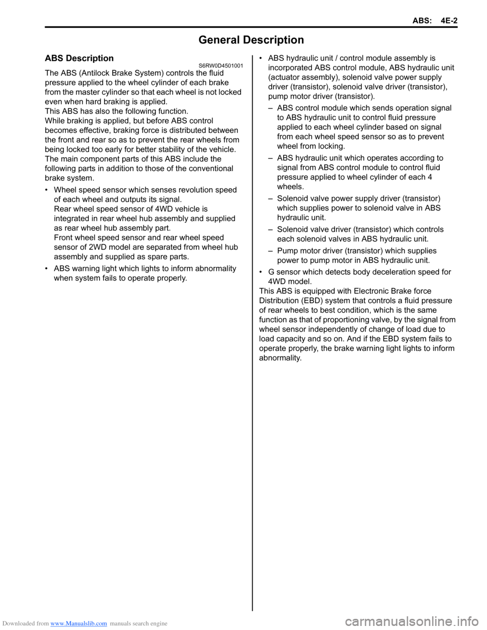
ABS DescriptionS6RW0D4501001
The ABS (Antilock Brake System) controls the fluid
pressure applied to the wheel cylinder of each brake
from the master cylinder so that each wheel is not locked
even when hard braking is applied.
This ABS has also the following function.
While braking is applied, but before ABS control
becomes effective, braking force is distributed between
the front and rear so as to prevent the rear wheels from
being locked too early for better stability of the vehicle.
The main component parts of this ABS include the
following parts in addition to those of the conventional
brake system.
• Wheel speed sensor which senses revolution speed
of each wheel and outputs its signal.
Rear wheel speed sensor of 4WD vehicle is
integrated in rear wheel hub assembly and supplied
as rear wheel hub assembly part.
Front wheel speed sensor and rear wheel speed
sensor of 2WD model are separated from wheel hub
assembly and supplied as spare parts.
• ABS warning light which lights to inform abnormality
when system fails to operate properly.• ABS hydraulic unit / control module assembly is
incorporated ABS control module, ABS hydraulic unit
(actuator assembly), solenoid valve power supply
driver (transistor), solenoid valve driver (transistor),
pump motor driver (transistor).
– ABS control module which sends operation signal
to ABS hydraulic unit to control fluid pressure
applied to each wheel cylinder based on signal
from each wheel speed sensor so as to prevent
wheel from locking.
– ABS hydraulic unit which operates according to
signal from ABS control module to control fluid
pressure applied to wheel cylinder of each 4
wheels.
– Solenoid valve power supply driver (transistor)
which supplies power to solenoid valve in ABS
hydraulic unit.
– Solenoid valve driver (transistor) which controls
each solenoid valves in ABS hydraulic unit.
– Pump motor driver (transistor) which supplies
power to pump motor in ABS hydraulic unit.
• G sensor which detects body deceleration speed for
4WD model.
This ABS is equipped with Electronic Brake force
Distribution (EBD) system that controls a fluid pressure
of rear wheels to best condition, which is the same
function as that of proportioning valve, by the signal from
wheel sensor independently of change of load due to
load capacity and so on. And if the EBD system fails to
operate properly, the brake warning light lights to inform
abnormality.
Page 610 of 1556
Downloaded from www.Manualslib.com manuals search engine 4E-5 ABS:
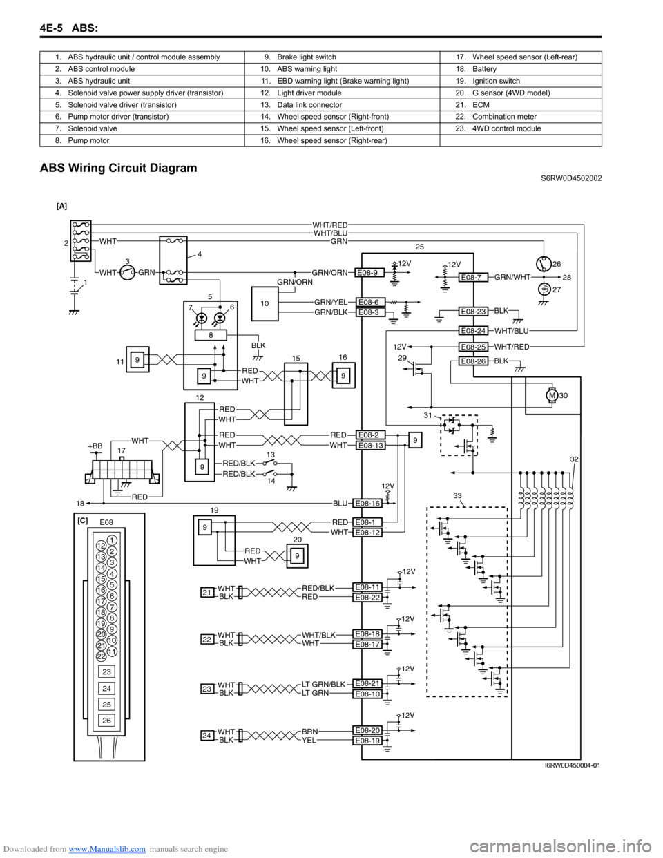
ABS Wiring Circuit DiagramS6RW0D4502002 1. ABS hydraulic unit / control module assembly 9. Brake light switch 17. Wheel speed sensor (Left-rear)
2. ABS control module 10. ABS warning light 18. Battery
3. ABS hydraulic unit 11. EBD warning light (Brake warning light) 19. Ignition switch
4. Solenoid valve power supply driver (transistor)12. Light driver module 20. G sensor (4WD model)
5. Solenoid valve driver (transistor) 13. Data link connector 21. ECM
6. Pump motor driver (transistor) 14. Wheel speed sensor (Right-front) 22. Combination meter
7. Solenoid valve 15. Wheel speed sensor (Left-front) 23. 4WD control module
8. Pump motor 16. Wheel speed sensor (Right-rear)
BLU
WHT12VGRN/ORN 34
30E08-9
RED
WHT26
WHT/RED
12V
E08-7
19GRN
GRN
E08-16
12V
21REDRED/BLK
12V
BLKWHTE08-22 E08-11
23BLKWHTLT GRN/BLKLT GRN
12V
E08-10 E08-21
E08-23
E08-26
E08-1E08-12
24BLKWHT
12V
YELBRNE08-19 E08-2027
1 2
E08-6
9
9
9
WHTRED
12VE08-25
M
BLK
BLK
WHT/BLUWHT/RED
WHT/BLUE08-24
WHT
E08 [C] [A]
1
2
3
4
5
6
7 12
13
14
15
16
17
18
19
20
21
228
9
10
11
23
24
25
26
GRN/WHT
22
12V
BLKWHTWHTWHT/BLKE08-17 E08-18
GRN/ORN28
2033
31
29
25
32
GRN/YELE08-3GRN/BLK10
8
17
18
+BB
RED/BLKRED/BLK
REDWHTREDWHT
RED
BLK
WHT
14 13 12 76 5
1516
REDWHT
11
RED
WHT
9 9
E08-13E08-2
99
I6RW0D450004-01
Page 611 of 1556
Downloaded from www.Manualslib.com manuals search engine ABS: 4E-6
17+BB
18BLU
WHT12VGRN/ORN 34
30E08-9
RED
WHT 1226
WHT/RED
12V
E08-7
19GRN
GRN
E08-16
12V
5
76
21REDRED/BLK
12V
BLKWHTE08-22 E08-11
23BLKWHTLT GRN/BLKLT GRN
12V
E08-10 E08-21
E08-23
E08-26
E08-1E08-12
24BLKWHT
12V
YELBRNE08-19 E08-20
27
1 2
RED/BLK
WHTRED
WHTRED
WHTRED9
E08-2E08-13WHT
E08-6
RED
9
9
11
9
9
9
REDWHT
WHTRED
12VE08-25
M
BLK
BLK
WHT/BLUWHT/RED
WHT/BLUE08-24
WHT
E08 [A]
1
2
3
4
5
6
7 12
13
14
15
16
17
18
19
20
21
228
9
10
11
23
24
25
26
GRN/WHT
22
12V
BLKWHTWHTWHT/BLKE08-17 E08-18
GRN/ORN28
2033
31
29
25
15
32
GRN/YELE08-3GRN/BLK
8
12V
12V
13
14RED/BLK
RED/BLU
WHTRED6
16
10
BLK [B]
I6RW0D450001-02
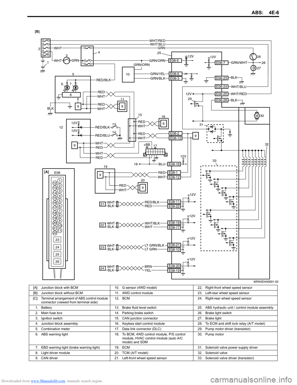
[A]: Junction block with BCM 10. G sensor (4WD model) 22. Right-front wheel speed sensor
[B]: Junction block without BCM 11. 4WD control module 23. Left-rear wheel speed sensor
[C]: Terminal arrangement of ABS control module
connector (viewed from terminal side)12. BCM 24. Right-rear wheel speed sensor
1. Battery 13. Brake fluid level switch 25. ABS hydraulic unit / control module assembly
2. Main fuse box 14. Parking brake switch 26. Brake light switch
3. Ignition switch 15. CAN junction connector 27. Brake light
4. Junction block assembly 16. Keyless start control module 28. To ECM and shift lock relay (A/T model)
5. Combination meter 17. Data link connector (DLC) 29. Pump motor driver (transistor)
6. ABS warning light 18. To BCM, 4WD control module, P/S control
module, HVAC control module (auto A/C
model) and SDM30. Pump motor
7. EBD warning light (brake warning light)19. ECM 31. Solenoid valve power supply driver
8. Light driver module 20. TCM (A/T model) 32. Solenoid valve
9. CAN driver 21. Left-front wheel speed sensor 33. Solenoid valve driver (transistor)
Page 612 of 1556
Downloaded from www.Manualslib.com manuals search engine 4E-7 ABS:
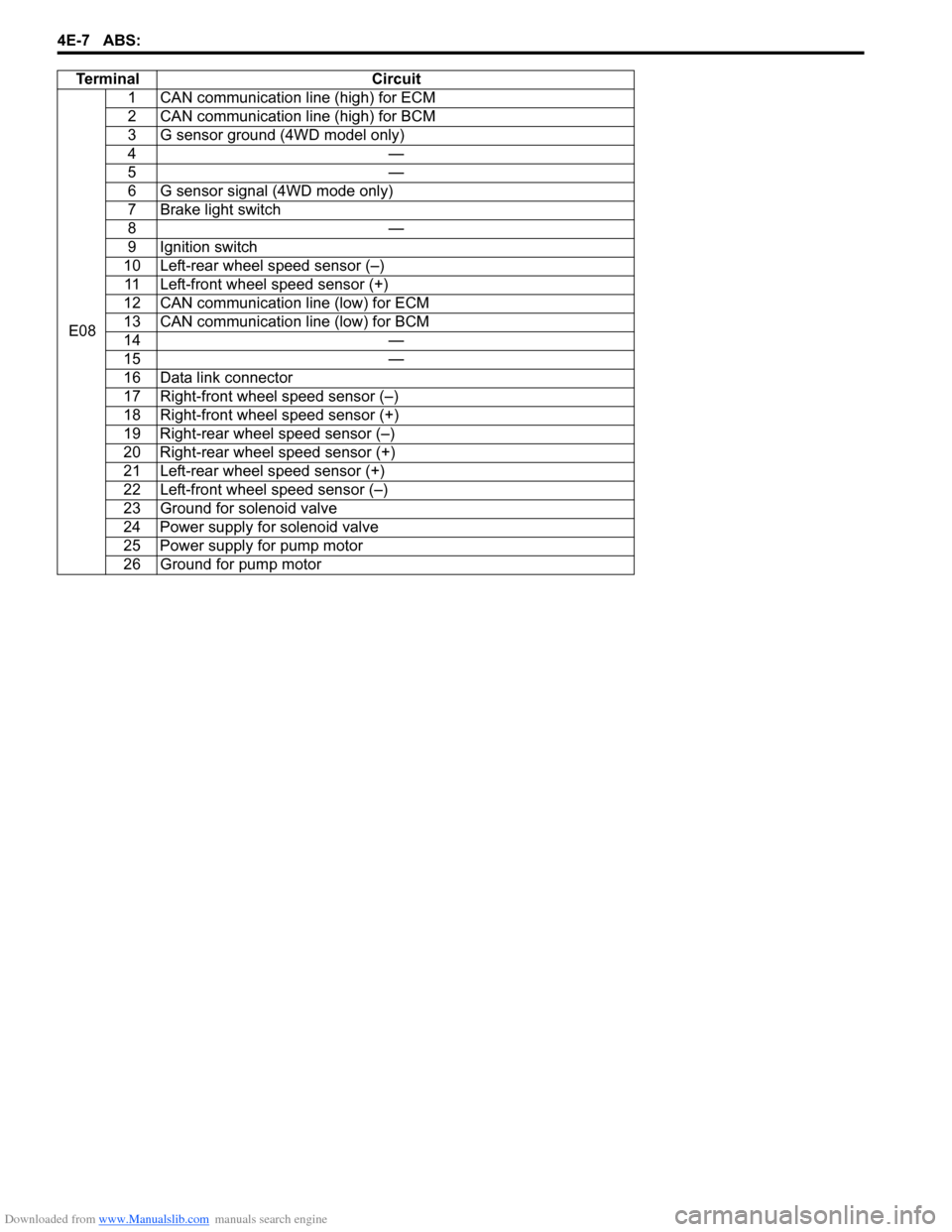
Te r m i n a l C i r c u i t
E081 CAN communication line (high) for ECM
2 CAN communication line (high) for BCM
3 G sensor ground (4WD model only)
4—
5—
6 G sensor signal (4WD mode only)
7 Brake light switch
8—
9 Ignition switch
10 Left-rear wheel speed sensor (–)
11 Left-front wheel speed sensor (+)
12 CAN communication line (low) for ECM
13 CAN communication line (low) for BCM
14 —
15 —
16 Data link connector
17 Right-front wheel speed sensor (–)
18 Right-front wheel speed sensor (+)
19 Right-rear wheel speed sensor (–)
20 Right-rear wheel speed sensor (+)
21 Left-rear wheel speed sensor (+)
22 Left-front wheel speed sensor (–)
23 Ground for solenoid valve
24 Power supply for solenoid valve
25 Power supply for pump motor
26 Ground for pump motor
Page 628 of 1556
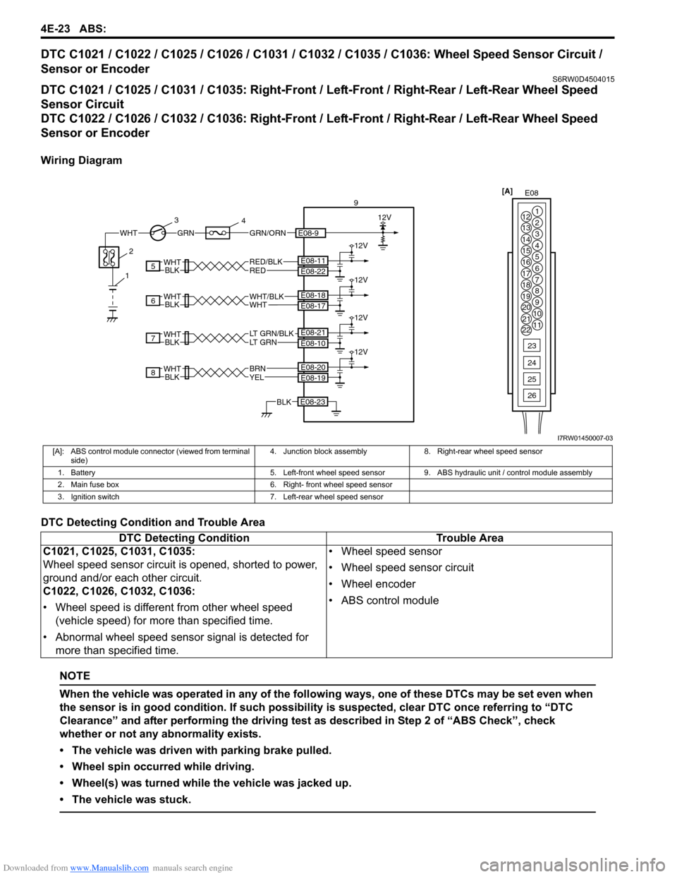
Downloaded from www.Manualslib.com manuals search engine 4E-23 ABS:
DTC C1021 / C1022 / C1025 / C1026 / C1031 / C1032 / C1035 / C1036: Wheel Speed Sensor Circuit /
Sensor or Encoder
S6RW0D4504015
DTC C1021 / C1025 / C1031 / C1035: Right-Front / Left-Front / Right-Rear / Left-Rear Wheel Speed
Sensor Circuit
DTC C1022 / C1026 / C1032 / C1036: Right-Front / Left-Front / Right-Rear / Left-Rear Wheel Speed
Sensor or Encoder
Wiring Diagram
DTC Detecting Condition and Trouble Area
NOTE
When the vehicle was operated in any of the following ways, one of these DTCs may be set even when
the sensor is in good condition. If such possibility is suspected, clear DTC once referring to “DTC
Clearance” and after performing the driving test as described in Step 2 of “ABS Check”, check
whether or not any abnormality exists.
• The vehicle was driven with parking brake pulled.
• Wheel spin occurred while driving.
• Wheel(s) was turned while the vehicle was jacked up.
• The vehicle was stuck.
E08 [A]
1
2
3
4
5
6
7 12
13
14
15
16
17
18
19
20
21
228
9
10
11
23
24
25
26
WHTGRNGRN/ORN
3
4
E08-9
9
12V
8
7
6
5
BLKWHT
BLKWHT
REDRED/BLK
LT GRN/BLKLT GRN
E08-22 E08-11
E08-10 E08-21
E08-23BLK
12V
12V
12V
12V
BLKWHT
BLKWHTWHTWHT/BLK
E08-17 E08-18
YELBRN
E08-19 E08-20
12
I7RW01450007-03
[A]: ABS control module connector (viewed from terminal
side)4. Junction block assembly 8. Right-rear wheel speed sensor
1. Battery 5. Left-front wheel speed sensor 9. ABS hydraulic unit / control module assembly
2. Main fuse box 6. Right- front wheel speed sensor
3. Ignition switch 7. Left-rear wheel speed sensor
DTC Detecting Condition Trouble Area
C1021, C1025, C1031, C1035:
Wheel speed sensor circuit is opened, shorted to power,
ground and/or each other circuit.
C1022, C1026, C1032, C1036:
• Wheel speed is different from other wheel speed
(vehicle speed) for more than specified time.
• Abnormal wheel speed sensor signal is detected for
more than specified time.• Wheel speed sensor
• Wheel speed sensor circuit
• Wheel encoder
• ABS control module
Page 629 of 1556

Downloaded from www.Manualslib.com manuals search engine ABS: 4E-24
DTC Troubleshooting
Step Action Yes No
1Was “ABS Check” performed?Go to Step 2. Go to “ABS Check”.
2Check tire condition
1) Check that tire pressure is specifications.
Are they in good condition?Go to Step 3. Replace tire or adjust
tire pressure and
recheck.
3Wheel speed sensor circuit check
1) Disconnect ABS hydraulic unit / control module
connector and applicable wheel speed sensor connector
with ignition switch turned OFF.
2) Check for proper connection to ABS hydraulic unit /
control module connector at applicable terminals and
terminals of applicable wheel speed sensor.
3) If OK then check applicable wheel speed sensor circuit
for open, short and high resistance.
Is each applicable wheel speed sensor circuit in good
condition?Go to Step 4. Repair circuit and
recheck
4Wheel speed sensor check
1) Inspection applicable wheel speed sensor referring to
“Front and Rear Wheel Speed Sensor Inspection”.
Is it in good condition?Go to Step 5. Clean or replace.
5Wheel speed sensor encoder check
1) Inspection applicable wheel speed sensor encoder
referring to “Front Wheel Speed Sensor Encoder On-
Vehicle Inspection” and/or “Rear Wheel Speed Sensor
Encoder On-Vehicle Inspection”.
Is it in good condition?Go to Step 6. Clean or replace wheel
hub assembly.
6Wheel speed sensor signal check
1) Inspection applicable wheel speed sensor referring to
“Front and Rear Wheel Speed Sensor On-Vehicle
Inspection”.
Is it in good condition?Substitute a known-
good wheel hub
assembly and recheck.
If DTC detected,
substitute a known-
good ABS hydraulic unit
/ control module and
recheck.Replace wheel speed
sensor and recheck.