Service wire SUZUKI SX4 2006 1.G Service Owner's Manual
[x] Cancel search | Manufacturer: SUZUKI, Model Year: 2006, Model line: SX4, Model: SUZUKI SX4 2006 1.GPages: 1556, PDF Size: 37.31 MB
Page 1043 of 1556
Downloaded from www.Manualslib.com manuals search engine Air Bag System: 8B-4
• Never attempt to disassemble the seat belt
pretensioners (retractor assembly).
• If any abnormality is found, be sure to replace it with
new one as an assembly.
• When an abnormality is noted as existing in the live
(inactivated) seat belt pretensioner, be sure to activate
it before discarding it.
• When grease, cleaning agent oil, water, etc., got on
the seat belt pretensioners (retractor assembly), wipe
it off immediately with a dry cloth.
• If seat belt pretensioner was dropped from a height of
30 cm (1 ft) or more, it should be replaced with a new
one as an assembly.
WARNING!
• For handling and storage of a live seat belt
pretensioner, select a place where the
ambient temperature below 65 °C (150 °F),
without high humidity and away from
electric noise.
• Never carry the seat belt pretensioner by
webbing.
• When placing a live seat belt pretensioner
on the workbench or other surface, be sure
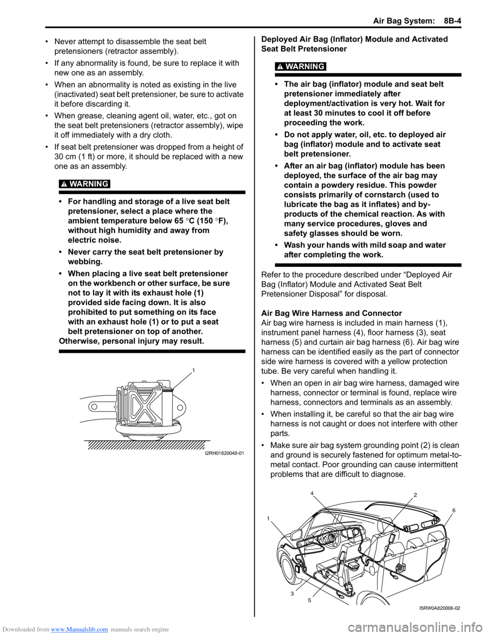
not to lay it with its exhaust hole (1)
provided side facing down. It is also
prohibited to put something on its face
with an exhaust hole (1) or to put a seat
belt pretensioner on top of another.
Otherwise, personal injury may result.
Deployed Air Bag (Inflator) Module and Activated
Seat Belt Pretensioner
WARNING!
• The air bag (inflator) module and seat belt
pretensioner immediately after
deployment/activation is very hot. Wait for
at least 30 minutes to cool it off before
proceeding the work.
• Do not apply water, oil, etc. to deployed air
bag (inflator) module and to activate seat
belt pretensioner.
• After an air bag (inflator) module has been
deployed, the surface of the air bag may
contain a powdery residue. This powder
consists primarily of cornstarch (used to
lubricate the bag as it inflates) and by-
products of the chemical reaction. As with
many service procedures, gloves and
safety glasses should be worn.
• Wash your hands with mild soap and water
after completing the work.
Refer to the procedure described under “Deployed Air
Bag (Inflator) Module and Activated Seat Belt
Pretensioner Disposal” for disposal.
Air Bag Wire Harness and Connector
Air bag wire harness is included in main harness (1),
instrument panel harness (4), floor harness (3), seat
harness (5) and curtain air bag harness (6). Air bag wire
harness can be identified easily as the part of connector
side wire harness is covered with a yellow protection
tube. Be very careful when handling it.
• When an open in air bag wire harness, damaged wire
harness, connector or terminal is found, replace wire
harness, connectors and terminals as an assembly.
• When installing it, be careful so that the air bag wire
harness is not caught or does not interfere with other
parts.
• Make sure air bag system grounding point (2) is clean
and ground is securely fastened for optimum metal-to-
metal contact. Poor grounding can cause intermittent
problems that are difficult to diagnose.
1
I2RH01820048-01
4
12
6
3
5
I5RW0A820006-02
Page 1129 of 1556

Downloaded from www.Manualslib.com manuals search engine Air Bag System: 8B-90
• Improperly formed or damaged terminals.
Check each connector terminal in problem circuits
carefully to ensure good contact tension by using the
corresponding mating terminal included in the
connector test adapter kit (special tool).
If contact tension is not enough, reform the terminal to
increase contact tension or replace it.
Special tool
(A): 09932–76010 Connector test adapter kit
• Poor terminal-to-wire connection.
Check each wire harness in problem circuits for poor
connection by shaking it by hand lightly. If any
abnormal condition is found, change the wire harness
assembly or component parts with new ones.
• Wire insulation which is rubbed through, causing an
intermittent short as the bare area touches other
wiring or parts of the vehicle.
• Wire broken inside the insulation. This condition could
cause a continuity check to show a good circuit, but if
only 1 or 2 strands of a multi-strand-type wire are
intact, resistance could be far too high.
Repair and Inspection Required after AccidentS6RW0D8204048
CAUTION!
• All air bag system components, including
the electrical harness (component
mounting points), must be inspected after
an accident. If any components are
damaged or bent, they must be replaced
even if air bag system activation did not
occur.
• Never use air bag system parts from
another vehicle.
• Do not attempt to service the parts below.
Service of these parts is by replacement
only.
– Driver / Passenger air bag (inflator)
modules
– Driver / Passenger side-air bag (inflator)
modules
– Driver / Passenger side curtain-air bag
(inflator) modules
– Driver / Passenger seat belt
pretensioners
– Forward impact-sensor
– Driver / Passenger side impact-sensors
–SDM
– Contact coil and combination switch
assembly
– Air bag wire harness in main harness,
instrument panel harness, floor harness,
passenger air bag harness, side-air bag
harness and side curtain-air bag
harness.
• Proper operation of the sensors and air
bag system requires that any repairs to the
vehicle structure return it to its original
production configuration.
(A)
I4RS0A820045-01
IYSQ01010028-01
IYSQ01820025-01
Page 1136 of 1556
Downloaded from www.Manualslib.com manuals search engine 8B-97 Air Bag System:
Driver Air Bag (Inflator) Module InspectionS6RW0D8206006
WARNING!
Never disassemble air bag (inflator) module
or measure its resistance. Otherwise,
personal injury may result.
CAUTION!
If air bag (inflator) module was dropped from
a height of 90 cm (3 ft) or more, it should be
replaced.
Check air bag (inflator) module visually and if any of the
following is found, replace it with a new one.
• Air bag being deployed
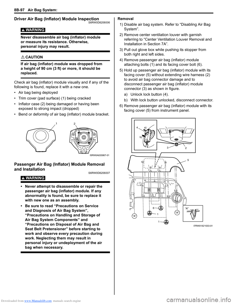
• Trim cover (pad surface) (1) being cracked
• Inflator case (2) being damaged or having been
exposed to strong impact (dropped)
• Bend or deformity of air bag (inflator) module bracket.
Passenger Air Bag (Inflator) Module Removal
and Installation
S6RW0D8206007
WARNING!
• Never attempt to disassemble or repair the
passenger air bag (inflator) module. If any
abnormality is found, be sure to replace it
with new one as an assembly.
• Be sure to read “Precautions on Service
and Diagnosis of Air Bag System”,
“Precautions on Handling and Storage of
Air Bag System Components” and
“Precautions on Disposal of Air Bag and
Seat Belt Pretensioner” before starting to
work and observe every precaution during
work. Neglecting them may result in
personal injury or undeployment of the air
bag when necessary.
Removal
1) Disable air bag system. Refer to “Disabling Air Bag
System”.
2) Remove center ventilation louver with garnish
referring to “Center Ventilation Louver Removal and
Installation in Section 7A”.
3) Pull out glove box while pushing its stopper from
both right and left sides.
4) Remove passenger air bag (inflator) module
attaching bolts (1) and its facing cover bolt (6).
5) Hold up passenger air bag (inflator) module with its
facing cover (5) without extending wire harness (2)
to avoid air bag connector damage and to
disconnect passenger air bag (inflator) module
connector (3) as shown in figure.
a) Unlock lock button (4).
b) With lock button unlocked, disconnect connector.
6) Remove passenger air bag (inflator) module with its
facing cover (5) from instrument panel.
1
2
I5RW0A820067-01
“A”
5
“A”“A”
3
4a)
b)
2
6
1 1
I7RW01821033-01
Page 1138 of 1556

Downloaded from www.Manualslib.com manuals search engine 8B-99 Air Bag System:
Passenger Air Bag (Inflator) Module InspectionS6RW0D8206008
WARNING!
• Never measure resistance of passenger air
bag (inflator) module or disassemble it.
Otherwise personal injury may result.
• Never attempt to disassemble or repair the
passenger air bag (inflator) module. If any
abnormality is found, be sure to replace it
with new one as an assembly.
• Be sure to read “Precautions on Service
and Diagnosis of Air Bag System”,
“Precautions on Handling and Storage of
Air Bag System Components” and
“Precautions on Disposal of Air Bag and
Seat Belt Pretensioner” before starting to
work and observe every precaution during
work. Neglecting them may result in
personal injury or undeployment of the air
bag when necessary.
CAUTION!
If air bag (Inflator) module was dropped from
a height of 90 cm (3 ft) or more, it should be
replaced.
Check air bag (inflator) module appearance visually for
the following symptoms and if any one of them is found,
replace with a new one.
• Air bag has deployed.
• Wire harness or connector is damaged.
• Air bag (inflator) module is damaged or a strong
impact was applied to it.
• Bend or deformity of air bag (inflator) module bracket.
Side-Air Bag (Inflator) Module Removal and
Installation
S6RW0D8206020
WARNING!
• Never attempt to disassemble or repair the
side-air bag (inflator) module. If any
abnormality is found, be sure to replace it
with new one as an assembly.
• Be sure to read “Precautions on Service
and Diagnosis of Air Bag System”,
“Precautions on Handling and Storage of
Air Bag System Components” and
“Precautions on Disposal of Air Bag and
Seat Belt Pretensioner” before starting to
work and observe every precaution during
work. Neglecting them may result in
personal injury or undeployment of the air
bag when necessary.
I5RW0A820072-03
1. Side-air bag (inflator) module 6. Sleeve
2. Seat back frame bracket 7. Sleeve lock nut
3. Side-air bag (inflator) module
connector8. Fastener
4. Seat back : 2.5 N⋅m (0.25 kgf-m, 2.0
lb-ft)
5. Air bag harness in floor harness : Do not reuse.
12
3
4
5
(a)7 6
8
2
1
I7RW01822144-01
Page 1140 of 1556

Downloaded from www.Manualslib.com manuals search engine 8B-101 Air Bag System:
2) Install new sleeve (1) and sleeve lock nut (2) to side-
air bag (inflator) module, then tighten nut to specified
torque.
Tightening torque
Sleeve lock nut (a): 2.5 N·m (0.25 kgf-m, 2.0 lb-
ft)
3) Connect side-air bag (inflator) module connector (1)
securely as shown in the figure.
a) Connect connector.
b) Lock connector with lock button (2).
4) Insert claw (1) of side-air bag (inflator) module on
installation hole (2).
5) Install side-air bag (inflator) module by pushing it into
fastener (3) securely.
6) Roll down backside seat back surface and fix seat
back surface fastener securely.Side-Air Bag (Inflator) InspectionS6RW0D8206021
WARNING!
• Never attempt to disassemble or repair the
side-air bag (inflator) module. If any
abnormality is found, be sure to replace it
with new one as an assembly.
• Be sure to read “Precautions on Service
and Diagnosis of Air Bag System” before
starting to work and observe every
precaution during work. Neglecting them
may result in personal injury or
undeployment of the air bag when
necessary.
CAUTION!
If air bag (inflator) module was dropped from
a height of 90 cm (3 ft) or more, it should be
replaced.
Check air bag (inflator) module appearance visually for
the following symptoms and if any one of them is found,
replace with a new one.
• Air bag has deployed.
• There is a crack in trim cover (pad surface).
• Wire harness or connector is damaged.
• Air bag (inflator) module is damaged or a strong
impact was applied to it.
• Bend or deformity of air bag (inflator) module bracket.
12, (a)
I4RS0A820073-02
1
2
a) b)
I4RS0A820070-01
1
2
3
I4RS0A820074-02
I4RS0A820075-02
Page 1141 of 1556
Downloaded from www.Manualslib.com manuals search engine Air Bag System: 8B-102
Side Curtain-Air Bag (Inflator) Module Removal
and Installation
S6RW0D8206022
WARNING!
• Never attempt to disassemble or repair the
side curtain-air bag (inflator) module. If any
abnormality is found, be sure to replace it
with new one as an assembly.
• Be sure to read “Precautions on Service
and Diagnosis of Air Bag System”,
“Precautions on Handling and Storage of
Air Bag System Components” and
“Precautions on Disposal of Air Bag and
Seat Belt Pretensioner” before starting to
work and observe every precaution during
work. Neglecting them may result in
personal injury or undeployment of the air
bag when necessary.
Removal
1) Disable air bag system. Refer to “Disabling Air Bag
System”.
2) Remove head lining referring to “Head Lining
Removal and Installation in Section 9H”.
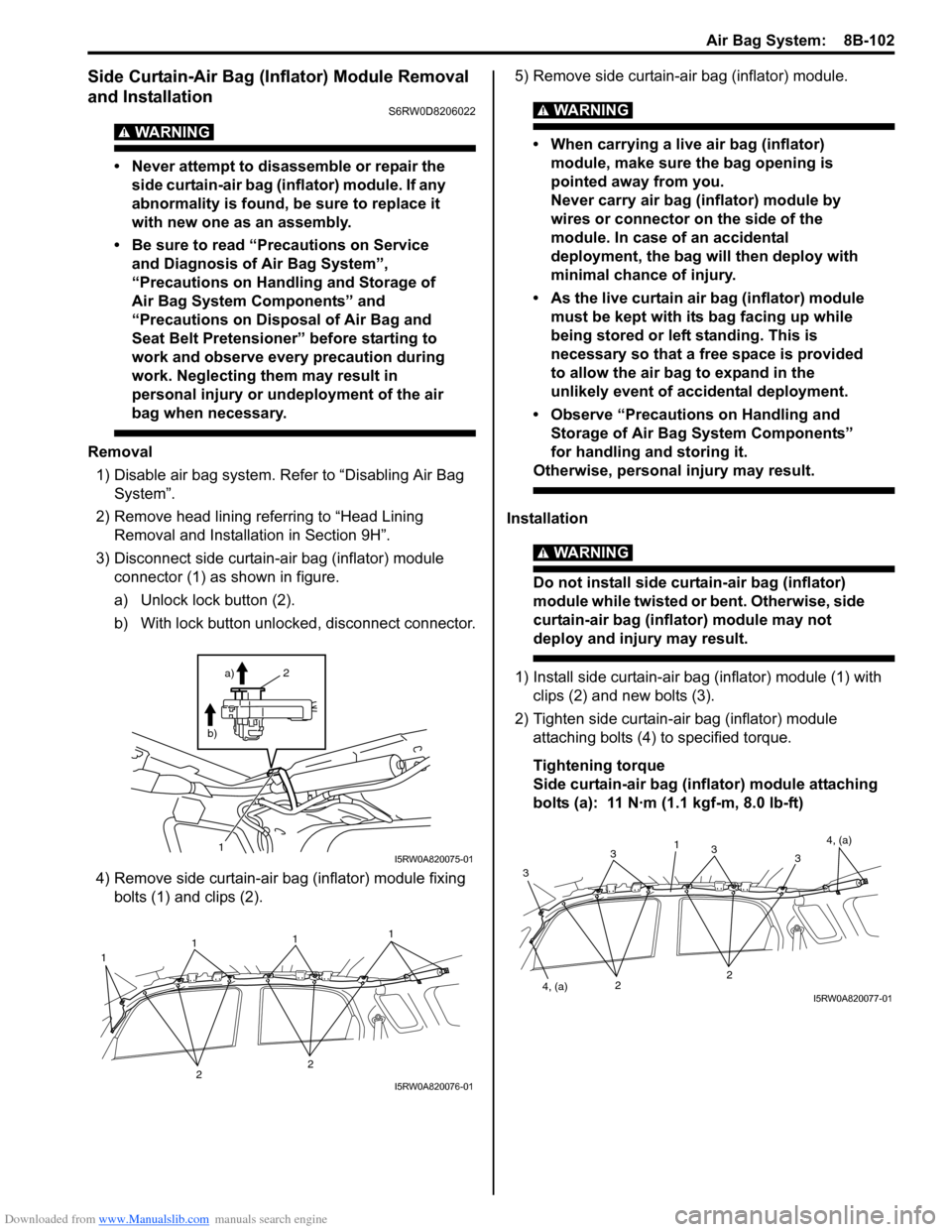
3) Disconnect side curtain-air bag (inflator) module
connector (1) as shown in figure.
a) Unlock lock button (2).
b) With lock button unlocked, disconnect connector.
4) Remove side curtain-air bag (inflator) module fixing
bolts (1) and clips (2).5) Remove side curtain-air bag (inflator) module.
WARNING!
• When carrying a live air bag (inflator)
module, make sure the bag opening is
pointed away from you.
Never carry air bag (inflator) module by
wires or connector on the side of the
module. In case of an accidental
deployment, the bag will then deploy with
minimal chance of injury.
• As the live curtain air bag (inflator) module
must be kept with its bag facing up while
being stored or left standing. This is
necessary so that a free space is provided
to allow the air bag to expand in the
unlikely event of accidental deployment.
• Observe “Precautions on Handling and
Storage of Air Bag System Components”
for handling and storing it.
Otherwise, personal injury may result.
Installation
WARNING!
Do not install side curtain-air bag (inflator)
module while twisted or bent. Otherwise, side
curtain-air bag (inflator) module may not
deploy and injury may result.
1) Install side curtain-air bag (inflator) module (1) with
clips (2) and new bolts (3).
2) Tighten side curtain-air bag (inflator) module
attaching bolts (4) to specified torque.
Tightening torque
Side curtain-air bag (inflator) module attaching
bolts (a): 11 N·m (1.1 kgf-m, 8.0 lb-ft)
1
2
a)
b)
I5RW0A820075-01
1111
22I5RW0A820076-01
4, (a)
333
34, (a)
1
22
I5RW0A820077-01
Page 1144 of 1556

Downloaded from www.Manualslib.com manuals search engine 8B-105 Air Bag System:
Side Impact-Sensor Removal and InstallationS6RW0D8206024
WARNING!
During service procedures, be very careful
when handling a sensor.
• Never strike or jar a sensor.
• A sensor bolt must be carefully torqued to
assure proper operation. Under loose
connection, it could cause improper
operation of the air bag system.
Removal
1) Disconnect negative (–) cable at battery.
2) Disable air bag system. Refer to “Disabling Air Bag
System”.
3) Remove center pillar lower trim.
4) Turn up floor carpet at front seat side.
5) Disconnect side impact-sensor connector (1) sliding
connector outer (2) as shown.
6) Remove side impact-sensor bolts (3), and side
impact-sensor (4) from side sill inner panel (5).
Installation
CAUTION!
Proper operation of side impact-sensor
requires that sensor is rigidly attached to
specified position.
1) Check that none of following faulty conditions exists.
• Bend, deformity or rust of under body.
• Foreign matter on mating surface of sensor.2) Install side impact-sensor (1) to side sill inner panel
(2) and tighten side impact-sensor bolt (3) to
specified torque.
Tightening torque
Side impact-sensor bolt (a): 9 N·m (0.9 kgf-m,
6.5 lb-ft)
3) Connect side impact-sensor connector (4) by
pushing connector till click is heard from it.
4) Return the carpet, and install center pillar lower trim.
5) Enable air bag system. Refer to “Enabling Air Bag
System”.
6) Connect negative (–) cable at battery.
Side Impact-Sensor InspectionS6RW0D8206025
WARNING!
During service procedures, be very careful
when handling a sensor.
• Never strike or jar a sensor.
• A sensor and mounting bracket bolts must
be carefully torqued to assure proper
operation. Under loose connection, it
could cause improper operation of the air
bag system.
CAUTION!
• Never disassemble side impact-sensor.
• Sensor should be replaced when it was
dropped from a height of 90 cm (3 ft) or
more.
• Check sensor for dents, crack, deformation.
• Check sensor connector (sensor side and harness
side), lock mechanism or sensor lead wire for
damage, crack, scorching or melting.
• Check connector terminals for bent, corrosion or rust.
If any faulty condition is found in above checks,
replace.
5
4
3
2
1I7RW01822149-01
2
1
3, (a)
4I7RW01822150-01
Page 1161 of 1556
Downloaded from www.Manualslib.com manuals search engine Table of Contents 9- i
9
Section 9
CONTENTS
Body, Cab and Accessories
Precautions ................................................. 9-1
Precautions............................................................. 9-1
Precautions on Body, Cab and Accessories ......... 9-1
Precautions for Body Service ................................ 9-1
Fastener Caution for Body Service ....................... 9-1
Wiring Systems........................................ 9A-1
Precautions........................................................... 9A-1
Cautions in Body Electrical System Servicing..... 9A-1
General Description ............................................. 9A-1
Abbreviations ...................................................... 9A-1
Wire / Connector Color Symbols ......................... 9A-1
Symbols and Marks ............................................ 9A-2
How to Read Connector Layout Diagram ........... 9A-4
How to Read Connector Codes and Terminal
Nos.................................................................... 9A-5
How to Read Ground Point ................................. 9A-8
How to Read Power Supply Diagram.................. 9A-9
How to Read System Circuit Diagram................. 9A-9
Connector Layout Diagram ............................... 9A-11
Connector Layout Diagram ............................... 9A-11
Engine Compartment ........................................ 9A-11
Instrument Panel ............................................... 9A-19
Door, Roof......................................................... 9A-25
Floor .................................................................. 9A-28
Rear .................................................................. 9A-32
Ground Point ...................................................... 9A-33
Ground (earth) Point ......................................... 9A-33
Power Supply Diagram ...................................... 9A-34
Power Supply Diagram ..................................... 9A-34
Fuses and the Protected Parts ......................... 9A-36
Fuses in Main Fuse Box ................................... 9A-36
Individual Circuit Fuse Box No. 1 ...................... 9A-37
Individual Circuit Fuse Box No. 2 (In J/B
(Except Taiwan)) ............................................. 9A-38
Individual Circuit Fuse Box No. 2 (In J/B
(Taiwan)) ......................................................... 9A-40
Junction Block (J/B) Connector / Fuse Layout .. 9A-42
Junction Block Inner Circuit (Overview
(Except Taiwan)) ............................................. 9A-43
Junction Block Inner Circuit (Detail (Except
Taiwan)) .......................................................... 9A-45
Junction Block Inner Circuit (Overview
(Taiwan)) ......................................................... 9A-50Junction Block Inner Circuit (Detail (Taiwan)) ... 9A-52
System Circuit Diagram.....................................9A-57
System Circuit Diagram .................................... 9A-57
A-1 Cranking System Circuit Diagram .............. 9A-58
A-2 Charging System Circuit Diagram .............. 9A-59
A-3 Ignition System Circuit Diagram (M15A
engine, M16A engine) ..................................... 9A-60
A-3 Ignition System Circuit Diagram (J20A
engine) ............................................................ 9A-61
A-4 Cooling System Circuit Diagram (M15A
engine, M16A engine) ..................................... 9A-62
A-4 Cooling System Circuit Diagram (J20A
engine) ............................................................ 9A-63
A-5 Engine and A/C Control System Circuit
Diagram (M15A engine) .................................. 9A-64
A-5 Engine and A/C Control System Circuit
Diagram (M16A engine) .................................. 9A-68
A-5 Engine and A/C Control System Circuit
Diagram (J20A engine) ................................... 9A-72
A-6 A/T Control System Circuit Diagram........... 9A-76
A-7 Immobilizer System Circuit Diagram .......... 9A-78
A-8 Body Control System Circuit Diagram
(Except Taiwan) .............................................. 9A-79
A-8 Body Control System Circuit Diagram
(Taiwan) .......................................................... 9A-83
A-10 4WD Control System (Except Taiwan) ..... 9A-87
B-1 Windshield Wiper and Washer Circuit
Diagram........................................................... 9A-88
B-2 Rear Wiper and Washer Circuit Diagram
(Except Taiwan) .............................................. 9A-89
B-2 Rear Wiper and Washer Circuit Diagram
(Taiwan) .......................................................... 9A-90
B-3 Rear Defogger Circuit Diagram (Except
Taiwan) ........................................................... 9A-91
B-3 Rear Defogger Circuit Diagram (Taiwan) ... 9A-92
B-4 Power Window Circuit Diagram .................. 9A-93
B-5 Power Door Lock Circuit Diagram (Except
Taiwan) ........................................................... 9A-95
B-5 Power Door Lock Circuit Diagram
(Taiwan) .......................................................... 9A-97
B-6 Power Mirror Circuit Diagram (Except
Taiwan) ........................................................... 9A-99
B-6 Power Mirror Circuit Diagram (Taiwan) .... 9A-100
B-7 Horn Circuit Diagram ................................ 9A-101
B-8 Seat Heater Circuit Diagram..................... 9A-102
Page 1164 of 1556
Downloaded from www.Manualslib.com manuals search engine 9-iv Table of Contents
Front Speaker Removal and Installation (If
Equipped) ........................................................9C-19
Rear Speaker Removal and Installation (If
Equipped) ........................................................9C-19
GPS Antenna Removal and Installation (If
Equipped) ........................................................9C-20
Horn Removal and Installation ..........................9C-20
Horn Inspection .................................................9C-20
Horn Relay Inspection .......................................9C-20
Antenna Base Removal and Installation ...........9C-21
Remote Audio Control Switch Removal and
Installation (If Equipped) .................................9C-21
Remote Audio Control Switch Inspection (If
Equipped) ........................................................9C-22
Vehicle Speed Signal Inspection (For Audio
Unit) (If Equipped) ...........................................9C-22
Specifications .....................................................9C-22
Tightening Torque Specifications ......................9C-22
Wipers / Washers .................................... 9D-1
Diagnostic Information and Procedures ............ 9D-1
Front Wiper and Washer Symptom Diagnosis ....9D-1
Rear Wiper and Washer Symptom Diagnosis..... 9D-1
Repair Instructions ..............................................9D-2
Wipers and Washers Components .....................9D-2
Washer Tank and Washer Pump Removal
and Installation ..................................................9D-3
Washer Pump Inspection ....................................9D-3
Windshield Wiper Removal and Installation ........9D-3
Windshield Wiper Motor Inspection.....................9D-4
Rear Wiper Removal and Installation.................. 9D-6
Rear Wiper Motor Inspection ..............................9D-7
Windshield Wiper and Washer Switch
Removal and Installation ................................... 9D-8
Windshield Wiper and Washer Switch
Inspection .......................................................... 9D-8
Rear Wiper and Washer Switch Removal and
Installation .......................................................9D-10
Rear Wiper and Washer Switch Inspection.......9D-10
Rear Wiper Relay Removal and Installation .....9D-10
Rear Wiper Relay Inspection ............................9D-10
Specifications .....................................................9D-11
Tightening Torque Specifications ......................9D-11
Glass / Windows / Mirrors .......................9E-1
Precautions........................................................... 9E-1
Precautions for Power Window Service
(Pinching Prevention Function Model) .............. 9E-1
General Description ............................................. 9E-1
Rear End Door Window Defogger System
Description ........................................................ 9E-1
Schematic and Routing Diagram ........................ 9E-2
Power Window Circuit Diagram (Pinching
Prevention Function Model) .............................. 9E-2
Diagnostic Information and Procedures ............ 9E-3
Rear End door Window Defogger Symptom
Diagnosis .......................................................... 9E-3
Power Window Control System Symptom
Diagnosis .......................................................... 9E-3Inspection of Pinching Prevention Function
(Pinching Prevention Function Model) .............. 9E-4
Power Door Mirror Control System Symptom
Diagnosis .......................................................... 9E-4
Door Mirror Heater Symptom Diagnosis (If
Equipped) .......................................................... 9E-5
Repair Instructions .............................................. 9E-5
Windshield Components ..................................... 9E-5
Windshield Removal and Installation .................. 9E-6
Front Pillar Window Components...................... 9E-10
Front Pillar Window Removal and Installation... 9E-10
Rear Quarter Window Components .................. 9E-11
Rear Quarter Window Removal and
Installation ....................................................... 9E-11
Rear End Door Window Components ............... 9E-12
Rear End Door Glass Removal and
Installation ....................................................... 9E-12
Front Door Window Components ...................... 9E-13
Front Door Glass Removal and Installation ...... 9E-14
Front Door Window Regulator Removal and
Installation ....................................................... 9E-15
Front Door Window Regulator Inspection ......... 9E-15
Rear Door Window Components ...................... 9E-16
Rear Door Glass Removal and Installation ....... 9E-16
Rear Door Window Regulator Removal and
Installation ....................................................... 9E-18
Rear Door Window Regulator Inspection .......... 9E-18
Rear End Door Window Defogger Switch
Inspection ........................................................ 9E-18
Rear End Door Window Defogger Relay
Inspection ........................................................ 9E-19
Rear End Door Window Defogger Wire
Inspection ........................................................ 9E-19
Rear End Door Window Defogger Wire
Repair.............................................................. 9E-20
Power Window Main Switch Inspection ............ 9E-20
Power Window Sub Switch Inspection .............. 9E-22
Pulse Sensor and Its Circuit Inspection
(Pinching Prevention Function Model) ............ 9E-23
Power Window Main Switch Initialization
(Pinching Prevention Function Model) ............ 9E-24
Door Mirror Components................................... 9E-24
Door Mirror Removal and Installation................ 9E-25
Power Door Mirror Switch Inspection ................ 9E-25
Power Door Mirror Actuator Inspection ............. 9E-25
Door Mirror Heater Inspection (If Equipped) ..... 9E-26
Door Mirror Heater Switch Inspection (If
Equipped) ........................................................ 9E-26
Special Tools and Equipment ........................... 9E-26
Recommended Service Material ....................... 9E-26
Security and Locks...................................9F-1
General Description ............................................. 9F-1
Key Coding Construction .................................... 9F-1
Rear End Door Opener System Description ....... 9F-1
Component Location ........................................... 9F-2
Power Door Lock and Keyless Entry System
Component Location (If Equipped) ................... 9F-2
Diagnostic Information and Procedures ............ 9F-3
Page 1165 of 1556
Downloaded from www.Manualslib.com manuals search engine Table of Contents 9-v
Power Door Lock System Symptom
Diagnosis (If Equipped)..................................... 9F-3
Power Door Lock System Operation
Inspection (If Equipped) .................................... 9F-3
Keyless Entry System Symptom Diagnosis (If
Equipped).......................................................... 9F-4
Keyless Entry System Operation Inspection
(If Equipped) ..................................................... 9F-5
Door Lock Function of Keyless Start System
Symptom Diagnosis (If Equipped) .................... 9F-5
Rear End Door Opener System Symptom
Diagnosis (If Equipped)..................................... 9F-5
Rear End Door Opener System Operation
Inspection (If Equipped) .................................... 9F-5
Repair Instructions .............................................. 9F-6
Front Door Lock Assembly Components ............ 9F-6
Front Door Lock Assembly Removal and
Installation ......................................................... 9F-6
Front Door Lock Assembly Inspection ................ 9F-8
Power Door Lock Switch Inspection (If
Equipped).......................................................... 9F-8
Door Key Cylinder Switch Inspection (If
Equipped).......................................................... 9F-8
Power Door Lock Actuator Inspection (If
Equipped).......................................................... 9F-9
Rear Door Lock Assembly Components ........... 9F-10
Rear Door Lock Assembly Removal and
Installation ....................................................... 9F-10
Rear Door Lock Assembly Inspection ............... 9F-10
Rear End Door Lock Assembly Components.... 9F-11
Rear End Door Lock Assembly Removal and
Installation ....................................................... 9F-12
Rear End Door Lock Assembly Inspection........ 9F-12
Rear End Door Opener Switch Inspection (If
Equipped)........................................................ 9F-12
Replacement of Transmitter Battery (Other
than Keyless Start Model) ............................... 9F-13
Programming Transmitter Code for Keyless
Entry System (Other than Keyless Start
Model) ............................................................. 9F-13
Keyless Entry Answer Back Function
Change-over Procedure (If Equipped) ............ 9F-14
Keyless Entry Receiver Removal and
Installation (If Equipped)................................. 9F-14
Keyless Entry Receiver and Its Circuit
Inspection (If Equipped) .................................. 9F-15
Specifications..................................................... 9F-16
Tightening Torque Specifications ...................... 9F-16
Special Tools and Equipment ........................... 9F-16
Recommended Service Material ....................... 9F-16
Seats ......................................................... 9G-1
Diagnostic Information and Procedures ............9G-1
Front Seat Heater Symptom Diagnosis (If
Equipped)..........................................................9G-1
Repair Instructions ..............................................9G-2
Front Seat Components ......................................9G-2
Front Seat Removal and Installation ...................9G-3Front Seat Heater Switch (Driver and
Passenger Side) Inspection (If Equipped)........ 9G-3
Front Seat Heater Wire Inspection (If
Equipped) ......................................................... 9G-3
Rear Seat Components...................................... 9G-4
Rear Seat Removal and Installation................... 9G-4
Specifications ...................................................... 9G-5
Tightening Torque Specifications ....................... 9G-5
Special Tools and Equipment ............................ 9G-5
Recommended Service Material ........................ 9G-5
Interior Trim ............................................. 9H-1
Repair Instructions ..............................................9H-1
Floor Carpet Removal and Installation ................9H-1
Head Lining Removal and Installation.................9H-2
Console Box Components ..................................9H-3
Specifications .......................................................9H-4
Tightening Torque Specifications ........................9H-4
Hood / Fenders / Doors ............................ 9J-1
Repair Instructions .............................................. 9J-1
Hood Removal and Installation ........................... 9J-1
Hood Inspection and Adjustment ........................ 9J-1
Front Fender Components .................................. 9J-2
Front Fender Removal and Installation ............... 9J-2
Front Door Assembly Components ..................... 9J-3
Front Door Assembly Removal and
Installation ......................................................... 9J-3
Rear Door Assembly Components...................... 9J-5
Rear Door Assembly Removal and
Installation ......................................................... 9J-5
Rear End Door Assembly Components .............. 9J-6
Rear End Door Assembly Removal and
Installation ......................................................... 9J-6
Specifications ....................................................... 9J-8
Tightening Torque Specifications ........................ 9J-8
Special Tools and Equipment ............................. 9J-8
Recommended Service Material ......................... 9J-8
Body Structure......................................... 9K-1
Repair Instructions ..............................................9K-1
Front Bumper and Rear Bumper Components .... 9K-1
Cowl Top and Front Lower Crossmember
Components ...................................................... 9K-2
Specifications .......................................................9K-3
Body Dimensions ................................................ 9K-3
Panel Clearance................................................ 9K-10
Tightening Torque Specifications ...................... 9K-10
Paint / Coatings ........................................9L-1
General Description ............................................. 9L-1
Anti-Corrosion Treatment Construction............... 9L-1
Plastic Parts Finishing ......................................... 9L-2
Component Location ........................................... 9L-3
Sealant Application Areas ................................... 9L-3
Under Coating Application Areas ...................... 9L-10
Anti-Corrosion Compound Application Area ..... 9L-12
Exterior Trim ............................................ 9M-1