brake drum SUZUKI SX4 2006 1.G Service Owner's Manual
[x] Cancel search | Manufacturer: SUZUKI, Model Year: 2006, Model line: SX4, Model: SUZUKI SX4 2006 1.GPages: 1556, PDF Size: 37.31 MB
Page 751 of 1556
Downloaded from www.Manualslib.com manuals search engine Automatic Transmission/Transaxle: 5A-103
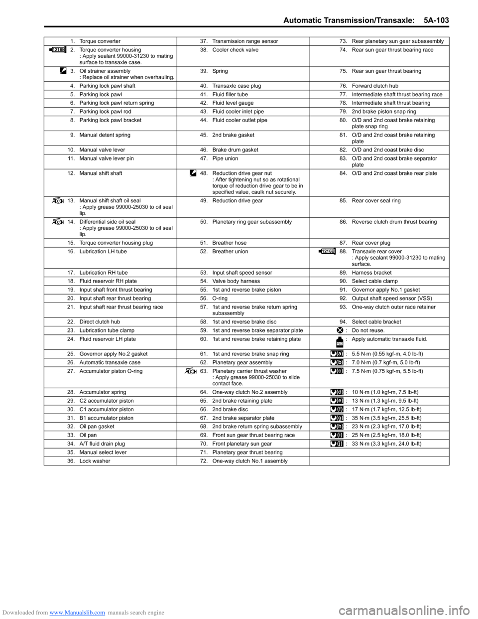
1. Torque converter 37. Transmission range sensor 73. Rear planetary sun gear subassembly
2. Torque converter housing
: Apply sealant 99000-31230 to mating
surface to transaxle case.38. Cooler check valve 74. Rear sun gear thrust bearing race
3. Oil strainer assembly
: Replace oil strainer when overhauling.39. Spring 75. Rear sun gear thrust bearing
4. Parking lock pawl shaft 40. Transaxle case plug 76. Forward clutch hub
5. Parking lock pawl 41. Fluid filler tube 77. Intermediate shaft thrust bearing race
6. Parking lock pawl return spring 42. Fluid level gauge 78. Intermediate shaft thrust bearing
7. Parking lock pawl rod 43. Fluid cooler inlet pipe 79. 2nd brake piston snap ring
8. Parking lock pawl bracket 44. Fluid cooler outlet pipe 80. O/D and 2nd coast brake retaining
plate snap ring
9. Manual detent spring 45. 2nd brake gasket 81. O/D and 2nd coast brake retaining
plate
10. Manual valve lever 46. Brake drum gasket 82. O/D and 2nd coast brake disc
11. Manual valve lever pin 47. Pipe union 83. O/D and 2nd coast brake separator
plate
12. Manual shift shaft 48. Reduction drive gear nut
: After tightening nut so as rotational
torque of reduction drive gear to be in
specified value, caulk nut securely.84. O/D and 2nd coast brake rear plate
13. Manual shift shaft oil seal
: Apply grease 99000-25030 to oil seal
lip.49. Reduction drive gear 85. Rear cover seal ring
14. Differential side oil seal
: Apply grease 99000-25030 to oil seal
lip.50. Planetary ring gear subassembly 86. Reverse clutch drum thrust bearing
15. Torque converter housing plug 51. Breather hose 87. Rear cover plug
16. Lubrication LH tube 52. Breather union 88. Transaxle rear cover
: Apply sealant 99000-31230 to mating
surface.
17. Lubrication RH tube 53. Input shaft speed sensor 89. Harness bracket
18. Fluid reservoir RH plate 54. Valve body harness 90. Select cable clamp
19. Input shaft front thrust bearing 55. 1st and reverse brake piston 91. Governor apply No.1 gasket
20. Input shaft rear thrust bearing 56. O-ring 92. Output shaft speed sensor (VSS)
21. Input shaft rear thrust bearing race 57. 1st and reverse brake return spring
subassembly93. One-way clutch outer race retainer
22. Direct clutch hub 58. 1st and reverse brake disc 94. Select cable bracket
23. Lubrication tube clamp 59. 1st and reverse brake separator plate : Do not reuse.
24. Fluid reservoir LH plate 60. 1st and reverse brake retaining plate : Apply automatic transaxle fluid.
25. Governor apply No.2 gasket 61. 1st and reverse brake snap ring : 5.5 N⋅m (0.55 kgf-m, 4.0 lb-ft)
26. Automatic transaxle case 62. Planetary gear assembly : 7.0 N⋅m (0.7 kgf-m, 5.0 lb-ft)
27. Accumulator piston O-ring 63. Planetary carrier thrust washer
: Apply grease 99000-25030 to slide
contact face.: 7.5 N⋅m (0.75 kgf-m, 5.5 lb-ft)
28. Accumulator spring 64. One-way clutch No.2 assembly : 10 N⋅m (1.0 kgf-m, 7.5 lb-ft)
29. C2 accumulator piston 65. 2nd brake retaining plate : 13 N⋅m (1.3 kgf-m, 9.5 lb-ft)
30. C1 accumulator piston 66. 2nd brake disc : 17 N⋅m (1.7 kgf-m, 12.5 lb-ft)
31. B1 accumulator piston 67. 2nd brake separator plate : 35 N⋅m (3.5 kgf-m, 25.5 lb-ft)
32. Oil pan gasket 68. 2nd brake return spring subassembly : 23 N⋅m (2.3 kgf-m, 17.0 lb-ft)
33. Oil pan 69. Front sun gear thrust bearing race : 25 N⋅m (2.5 kgf-m, 18.0 lb-ft)
34. A/T fluid drain plug 70. Front planetary sun gear : 33 N⋅m (3.3 kgf-m, 24.0 lb-ft)
35. Manual select lever 71. Planetary gear thrust bearing
36. Lock washer 72. One-way clutch No.1 assembly
Page 760 of 1556

Downloaded from www.Manualslib.com manuals search engine 5A-112 Automatic Transmission/Transaxle:
53) Remove 2nd brake piston assembly (1).
54) Remove 2nd brake return spring subassembly (2).
55) Remove 2nd brake separator plates (1), discs (2)
and retaining plate (3).
56) Remove brake drum gasket (1).
57) Remove one-way clutch outer race retainer (1).58) Check one-way clutch No.2 as follows.
• Ensure planetary carrier (1) rotates only in
counterclockwise direction “A”, never in clockwise
direction “B”.
• If the planetary carrier rotates both ways or does
not rotate either way, one-way clutch No.2
assembly will need to be replaced with new one-
way clutch No.2 assembly.
59) Remove one-way clutch No.2 assembly (1).
60) Remove planetary gear assembly (1).
1
2
I4RS0A510038-01
I2RH0B510127-01
I2RH0B510128-01
I2RH0B510129-01
I2RH0B510130-01
1
I4RS0A510039-01
I2RH0B510132-01
Page 776 of 1556
Downloaded from www.Manualslib.com manuals search engine 5A-128 Automatic Transmission/Transaxle:
Forward Clutch Piston Lip and Forward Clutch
Balancer Lip
Check each lip for wear, deformation, cut and/or
hardening. If necessary, replace.Forward Clutch Drum Lip
Check each lip for wear, deformation, cut and/or
hardening. If necessary, replace.
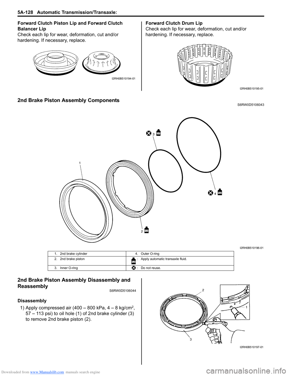
2nd Brake Piston Assembly ComponentsS6RW0D5106043
2nd Brake Piston Assembly Disassembly and
Reassembly
S6RW0D5106044
Disassembly
1) Apply compressed air (400 – 800 kPa, 4 – 8 kg/cm
2,
57 – 113 psi) to oil hole (1) of 2nd brake cylinder (3)
to remove 2nd brake piston (2).
I2RH0B510194-01
I2RH0B510195-01
I2RH0B510196-01
1. 2nd brake cylinder 4. Outer O-ring
2. 2nd brake piston : Apply automatic transaxle fluid.
3. Inner O-ring : Do not reuse.
I2RH0B510197-01
Page 796 of 1556
Downloaded from www.Manualslib.com manuals search engine 5A-148 Automatic Transmission/Transaxle:
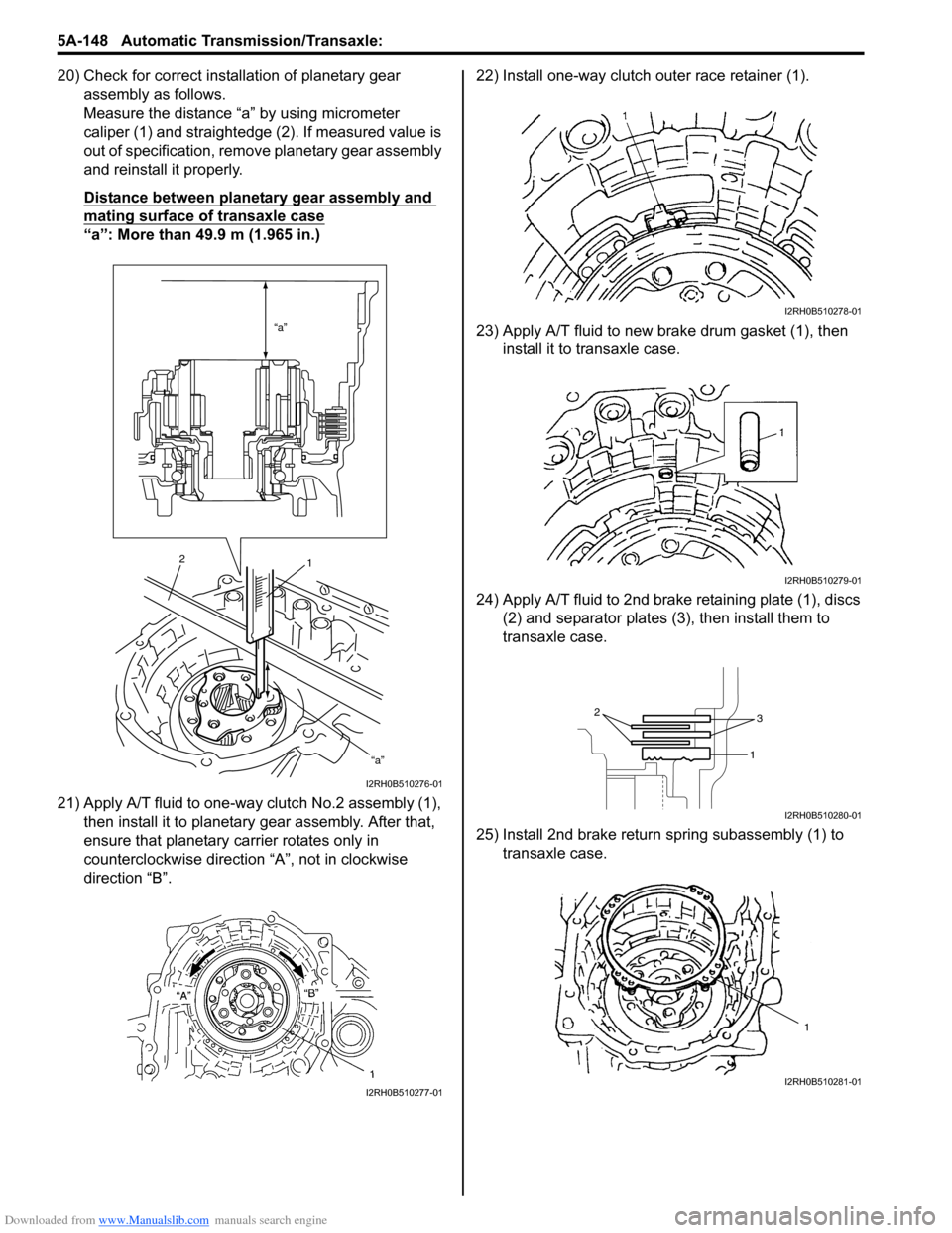
20) Check for correct installation of planetary gear
assembly as follows.
Measure the distance “a” by using micrometer
caliper (1) and straightedge (2). If measured value is
out of specification, remove planetary gear assembly
and reinstall it properly.
Distance between planetary gear assembly and
mating surface of transaxle case
“a”: More than 49.9 m (1.965 in.)
21) Apply A/T fluid to one-way clutch No.2 assembly (1),
then install it to planetary gear assembly. After that,
ensure that planetary carrier rotates only in
counterclockwise direction “A”, not in clockwise
direction “B”.22) Install one-way clutch outer race retainer (1).
23) Apply A/T fluid to new brake drum gasket (1), then
install it to transaxle case.
24) Apply A/T fluid to 2nd brake retaining plate (1), discs
(2) and separator plates (3), then install them to
transaxle case.
25) Install 2nd brake return spring subassembly (1) to
transaxle case.
“a”
“a”
2
1
I2RH0B510276-01
I2RH0B510277-01
I2RH0B510278-01
I2RH0B510279-01
2
3
1
I2RH0B510280-01
1
I2RH0B510281-01
Page 800 of 1556

Downloaded from www.Manualslib.com manuals search engine 5A-152 Automatic Transmission/Transaxle:
43) Measure O/D and 2nd coast brake piston stroke.
• Measure dimension “a” from end face of transaxle
case to O/D and 2nd coast brake rear plate (1)
using straightedge and micrometer caliper.
• Measure dimension “b” from O/D and 2nd coast
brake piston (2) to rear cover assembly mating
surface using straightedge and micrometer
caliper.
• Calculate piston stroke from measured value of
dimensions “a” and “b”.
• Piston stroke = “a” – “b”
O/D and 2nd coast brake piston stroke
Standard: 0.65 – 1.05 mm (0.026 – 0.041 in.)
When piston stroke is out of specification, select O/D
and 2nd coast brake rear plate with proper thickness
from among the following table and replace it.
CAUTION!
When brake disc, retaining plate, separator
plate and/or rear plate of O/D and 2nd coast
brake have been replaced, all learned
contents, which have been stored in TCM
memory by executing learning control,
should be initialized referring to “Learning
Control Initialization”.
Neglecting this initialization may cause
excessive shift shock.
Available O/D and 2nd coast brake rear plate
thickness
44) After applying A/T fluid to new 2nd brake gaskets (1),
install them to transaxle case (2).
45) After applying A/T fluid to reverse clutch drum thrust
bearing (1), install it to forward and reverse clutch
assembly (2).
46) Remove sealant attached to mating surface of
transaxle rear cover (1) completely.
47) Apply sealant to mating surface of transaxle rear
cover (1) by using a nozzle (2) as shown in figure by
such amount that its section is 1.2 mm (0.047 in.) in
diameter.
“A”: Sealant 99000–31230 (SUZUKI Bond
No.1216B) Thickness Identification mark
1.8 mm (0.071 in.) 1
2.0 mm (0.079 in.) 2
2.2 mm (0.087 in.) 3
2.4 mm (0.094 in.) 4
2.6 mm (0.102 in.) 5
I2RH0B510298-01
I2RH0B510299-01
I2RH0B510300-01
“A”2
1
I2RH0B510301-01
Page 869 of 1556
Downloaded from www.Manualslib.com manuals search engine Steering General Diagnosis: 6A-2
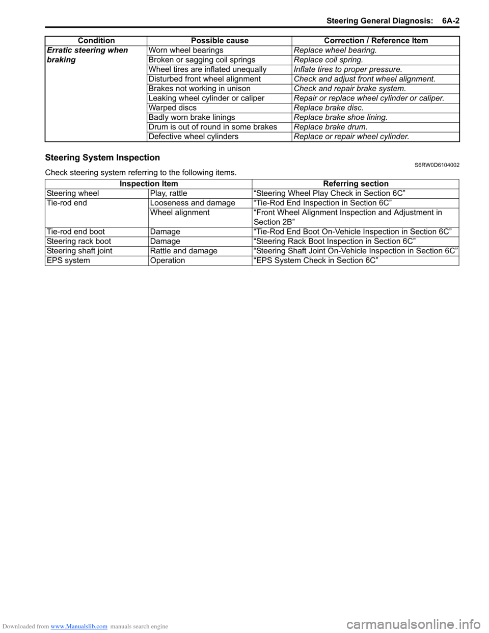
Steering System InspectionS6RW0D6104002
Check steering system referring to the following items.Erratic steering when
brakingWorn wheel bearingsReplace wheel bearing.
Broken or sagging coil springsReplace coil spring.
Wheel tires are inflated unequallyInflate tires to proper pressure.
Disturbed front wheel alignmentCheck and adjust front wheel alignment.
Brakes not working in unisonCheck and repair brake system.
Leaking wheel cylinder or caliperRepair or replace wheel cylinder or caliper.
Warped discsReplace brake disc.
Badly worn brake liningsReplace brake shoe lining.
Drum is out of round in some brakesReplace brake drum.
Defective wheel cylindersReplace or repair wheel cylinder. Condition Possible cause Correction / Reference Item
Inspection Item Referring section
Steering wheel Play, rattle “Steering Wheel Play Check in Section 6C”
Tie-rod end Looseness and damage “Tie-Rod End Inspection in Section 6C”
Wheel alignment “Front Wheel Alignment Inspection and Adjustment in
Section 2B”
Tie-rod end boot Damage “Tie-Rod End Boot On-Vehicle Inspection in Section 6C”
Steering rack boot Damage “Steering Rack Boot Inspection in Section 6C”
Steering shaft joint Rattle and damage “Steering Shaft Joint On-Vehicle Inspection in Section 6C”
EPS system Operation “EPS System Check in Section 6C”