intake manifold SUZUKI SX4 2006 1.G Service Owner's Manual
[x] Cancel search | Manufacturer: SUZUKI, Model Year: 2006, Model line: SX4, Model: SUZUKI SX4 2006 1.GPages: 1556, PDF Size: 37.31 MB
Page 124 of 1556

Downloaded from www.Manualslib.com manuals search engine 1A-74 Engine General Information and Diagnosis:
DTC P0111: Intake Air Temperature Circuit Range / PerformanceS6RW0D1104023
Wiring Diagram
DTC Detecting Condition and Trouble Area
DTC Confirmation Procedure
NOTE
Check to make sure that following conditions are satisfied when using this “DTC Confirmation
Procedure”.
• Intake air temperature at engine start: –10 °C (14 °F) to 80 °C (176 °F)
• Intake air temperature: –10 °C (14 °F) to 70 °C (158 °F)
• Engine coolant temperature at engine start: less than 30 °C (86 °F)
• Engine coolant temperature: 70 °C (158 °F) or more
• Altitude (barometric pressure): 2500 m, 8200 ft or less (560 mmHg, 74.4 kPa or more)
1) With ignition switch turned OFF, connect scan tool.
2) Turn ON ignition switch, clear DTC using scan tool.
3) Start engine and warm up to normal operating temperature. (ECT approx. 90 – 95 °C, 194 – 203 °F)
4) Run engine at idle speed for 10 min. or more.9MAP sensor output signal check
1) Check MAP sensor according to “Manifold Absolute
Pressure (MAP) Sensor Inspection (If Equipped) in
Section 1C”.
Is it in good condition?Substitute a known-
good ECM and recheck.Faulty MAP sensor. Step Action Yes No
E01C01
3 4
18 19 5 6 7 10 11
17 20
47 46 49 50 51 21 22
5216 259
24 14
29
55 57 54 53 59
60 582
26 27 28 15
30
56 4832 31 34 35 36 37 40 42 39 38 44
45 43 41 331 12 13
238 3 4
18 19 5 6 7 10 11
17 20
47 46 49 50 51 21 22
5216 259
24 14
29
55 57 54 53 59
60 582
26 27 28 15
30
56 4832 31 34 35 36 37 40 42 39 38 44
45 43 41 331 12 13
238
5V
2
BLK/YEL
GRY/BLU
GRY
GRY/BLU
1
GRN/BLK
C01-25
C01-55 34
C01-26
C01-27
BLK/RED
GRY/BLU
I6RW0D110024-01
1. MAF and IAT sensor 3. To other sensors
2. ECM 4. From main relay
DTC detecting condition Trouble area
Difference of maximum IAT minus minimum IAT is less than specified value while
ECT is over 70 °C (158 °F) after 10 min from cold engine start (ECT is lower than
30°C (86 °F) at engine start).
(2 driving cycle detection logic)• High resistance circuit
• MAF and IAT sensor
•ECM
Page 169 of 1556
Downloaded from www.Manualslib.com manuals search engine Engine General Information and Diagnosis: 1A-119
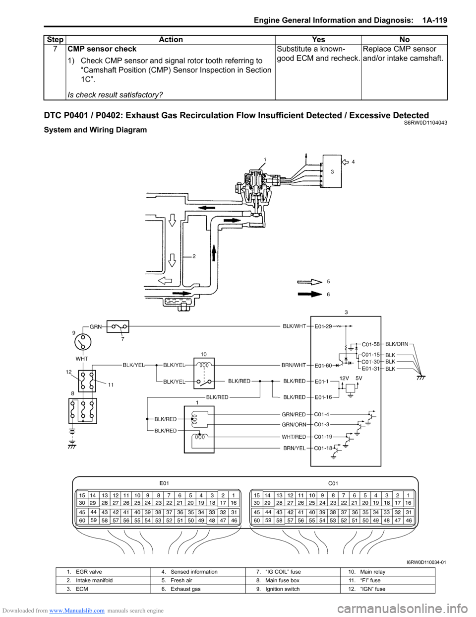
DTC P0401 / P0402: Exhaust Gas Recirculation Flow Insufficient Detected / Excessive DetectedS6RW0D1104043
System and Wiring Diagram7CMP sensor check
1) Check CMP sensor and signal rotor tooth referring to
“Camshaft Position (CMP) Sensor Inspection in Section
1C”.
Is check result satisfactory?Substitute a known-
good ECM and recheck.Replace CMP sensor
and/or intake camshaft. Step Action Yes No
I6RW0D110034-01
1. EGR valve 4. Sensed information 7. “IG COIL” fuse 10. Main relay
2. Intake manifold 5. Fresh air 8. Main fuse box 11. “FI” fuse
3. ECM 6. Exhaust gas 9. Ignition switch 12. “IGN” fuse
Page 170 of 1556
Downloaded from www.Manualslib.com manuals search engine 1A-120 Engine General Information and Diagnosis:
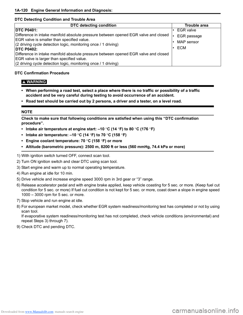
DTC Detecting Condition and Trouble Area
DTC Confirmation Procedure
WARNING!
• When performing a road test, select a place where there is no traffic or possibility of a traffic
accident and be very careful during testing to avoid occurrence of an accident.
• Road test should be carried out by 2 persons, a driver and a tester, on a level road.
NOTE
Check to make sure that following conditions are satisfied when using this “DTC confirmation
procedure”.
• Intake air temperature at engine start: –10 °C (14 °F) to 80 °C (176 °F)
• Intake air temperature: –10 °C (14 °F) to 70 °C (158 °F)
• Engine coolant temperature: 70 °C (158 °F) or more
• Altitude (barometric pressure): 2500 m, 8200 ft or less (560 mmHg, 74.4 kPa or more)
1) With ignition switch turned OFF, connect scan tool.
2) Turn ON ignition switch and clear DTC using scan tool.
3) Start engine and warm up to normal operating temperature.
4) Run engine at idle for 10 min.
5) Drive vehicle and increase engine speed 3000 rpm in 3rd gear or “3” range.
6) Release accelerator pedal and with engine brake applied, keep vehicle coasting for 5 sec. or more. (Keep fuel cut
condition for 5 sec. or more) If fuel cut condition is not kept for 5 sec. or more, coast down a slope in engine speed
1000 – 3000 rpm for 5 sec. or more.
7) Stop vehicle and run engine at idle.
8) For european market model, check whether EGR system readiness/monitoring test has completed or not by using
scan tool.
If evaporative system readiness/monitoring test has not completed, check vehicle conditions (environmental) and
repeat Steps 3) through 7).
9) Check DTC and pending DTC.DTC detecting condition Trouble area
DTC P0401:
Difference in intake manifold absolute pressure between opened EGR valve and closed
EGR valve is smaller than specified value.
(2 driving cycle detection logic, monitoring once / 1 driving)
DTC P0402:
Difference in intake manifold absolute pressure between opened EGR valve and closed
EGR valve is larger than specified value.
(2 driving cycle detection logic, monitoring once / 1 driving)• EGR valve
• EGR passage
• MAP sensor
•ECM
Page 175 of 1556
Downloaded from www.Manualslib.com manuals search engine Engine General Information and Diagnosis: 1A-125
DTC Confirmation Procedure
WARNING!
• When performing a road test, select a place where there is no traffic or possibility of a traffic
accident and be very careful during testing to avoid occurrence of an accident.
• Road test should be carried out by 2 persons, a driver and a tester, on a level road.
NOTE
Check to make sure that following conditions are satisfied when using this “DTC Confirmation
Procedure”.
• Intake air temperature at engine start: –10 (14 °F) to 80 °C (176 °F)
• Intake air temperature: –10 °C (14 °F) to 70 °C (158 °F)
• Engine coolant temp.: 70 °C, 158 °F or more
• Altitude (barometric pressure): 2500 m, 8200 ft or less (560 mmHg, 74.4 kPa or more)
1) Connect scan tool to DLC with ignition switch turned OFF.
2) Turn ON ignition switch and clear DTC using scan tool.
3) Increase vehicle speed to 40 – 50 mph, 60 – 80 km/h.
4) Keep above vehicle speed for 10 min. or more (Throttle valve opening is kept constant in this step).
5) Stop vehicle.
6) For european market model, check whether catalyst monitoring readiness/monitoring test has completed or not by
using scan tool.
If evaporative system readiness/monitoring test has not completed, check vehicle conditions (environmental) and
repeat Steps 3) through 5).
7) Check DTC and pending DTC.
DTC Troubleshooting
NOTE
Before this troubleshooting is performed, read the precautions for DTC troubleshooting referring to
“Precautions for DTC Troubleshooting”.
Step Action Yes No
1Was “Engine and Emission Control System Check”
performed?Go to Step 2. Go to “Engine and
Emission Control
System Check”.
2Exhaust system visual check
1) Check exhaust system for leaks, damage and loose
connection.
Is it in good condition?Go to Step 3. Repair or replace
defective part.
3HO2S-2 output voltage check
1) Check output voltage of HO2S-2 referring to “DTC
P0137 / P0138: O2 Sensor (HO2S) Circuit Low Voltage /
High Voltage (Sensor-2)”.
Is check result satisfactory?Replace exhaust
manifold (built in warm
up three way catalytic
converter) and exhaust
center pipe (built in
three way catalytic
converter).Check “BRN” and / or
“ORN” wires for open
and short, and
connections for poor
connection.
If wires and connections
are OK, replace HO2S-
2.
Page 215 of 1556

Downloaded from www.Manualslib.com manuals search engine Engine General Information and Diagnosis: 1A-165
DTC P2227 / P2228 / P2229: Barometric Pressure Circuit MalfunctionS6RW0D1104068
DTC P2227: Barometric Pressure Circuit Range / Performance
DTC P2228: Barometric Pressure Circuit Low
DTC P2229: Barometric Pressure Circuit High
System Description
Barometric pressure sensor is installed in ECM.
DTC Detecting Condition and Trouble Area6Wire harness check
1) Disconnect connectors from ECM with ignition switch
turned OFF.
2) Check for proper connection of ECM connector at “E01-
37”, “E01-52”, “E01-36” and “E01-51” terminals.
3) If OK, measure resistance between “GRN” wire terminal
of APP sensor assembly connector and vehicle body
ground, between “YEL” wire terminal of APP sensor
assembly connector and vehicle body ground.
Is each resistance infinity?Go to Step 7. “GRN” wire or “YEL”
wire is shorted to other
circuit.
7Wire harness check
1) Turn ON ignition switch.
2) Measure voltage between “E01-37” terminal of ECM
connector and engine ground, between “E01-36”
terminal of ECM connector and engine ground.
Is each voltage 0 V?Go to Step 8. “GRN” wire or “YEL”
wire is shorted to other
circuit.
8APP sensor assembly check
1) 1)Check APP sensor referring to “Accelerator Pedal
Position (APP) Sensor Assembly Inspection in Section
1C”.
Is output voltage within specified value?Substitute a known-
good ECM and recheck.Replace APP sensor
assembly. Step Action Yes No
DTC detecting condition Trouble area
DTC P2227:
Difference of barometric pressure value and intake manifold pressure value
is more than specified value while engine cranking.
(2 driving cycle detection logic)• Manifold absolute pressure sensor
performance problem
• Barometric pressure sensor in ECM
DTC P2228:
Barometric pressure signal is lower than specified value.
(1 driving cycle detection logic)• Barometric pressure sensor in ECM
DTC P2229:
Barometric pressure signal is higher than specified value.
(1 driving cycle detection logic)
Page 265 of 1556
Downloaded from www.Manualslib.com manuals search engine Aux. Emission Control Devices: 1B-2
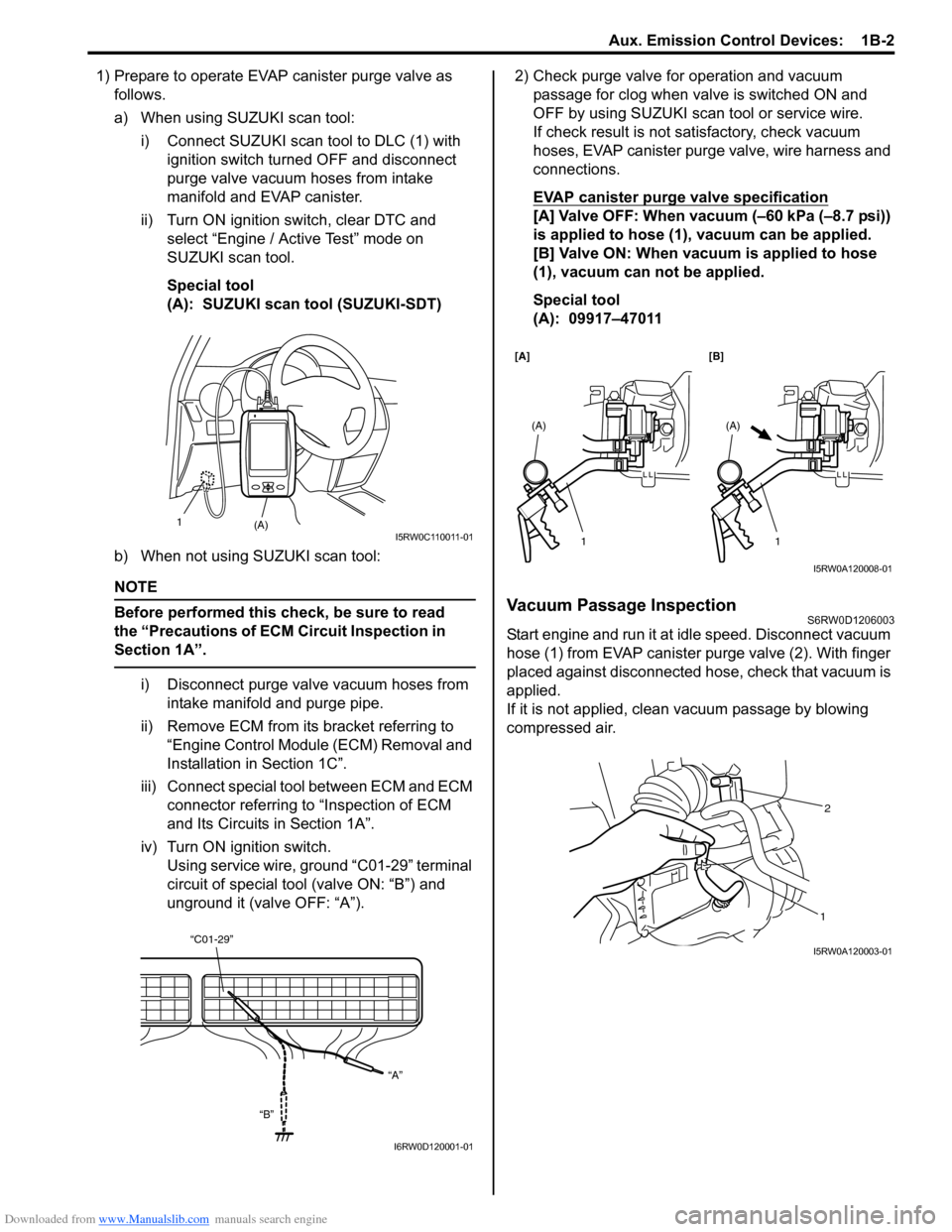
1) Prepare to operate EVAP canister purge valve as
follows.
a) When using SUZUKI scan tool:
i) Connect SUZUKI scan tool to DLC (1) with
ignition switch turned OFF and disconnect
purge valve vacuum hoses from intake
manifold and EVAP canister.
ii) Turn ON ignition switch, clear DTC and
select “Engine / Active Test” mode on
SUZUKI scan tool.
Special tool
(A): SUZUKI scan tool (SUZUKI-SDT)
b) When not using SUZUKI scan tool:
NOTE
Before performed this check, be sure to read
the “Precautions of ECM Circuit Inspection in
Section 1A”.
i) Disconnect purge valve vacuum hoses from
intake manifold and purge pipe.
ii) Remove ECM from its bracket referring to
“Engine Control Module (ECM) Removal and
Installation in Section 1C”.
iii) Connect special tool between ECM and ECM
connector referring to “Inspection of ECM
and Its Circuits in Section 1A”.
iv) Turn ON ignition switch.
Using service wire, ground “C01-29” terminal
circuit of special tool (valve ON: “B”) and
unground it (valve OFF: “A”).2) Check purge valve for operation and vacuum
passage for clog when valve is switched ON and
OFF by using SUZUKI scan tool or service wire.
If check result is not satisfactory, check vacuum
hoses, EVAP canister purge valve, wire harness and
connections.
EVAP canister purge valve specification
[A] Valve OFF: When vacuum (–60 kPa (–8.7 psi))
is applied to hose (1), vacuum can be applied.
[B] Valve ON: When vacuum is applied to hose
(1), vacuum can not be applied.
Special tool
(A): 09917–47011
Vacuum Passage InspectionS6RW0D1206003
Start engine and run it at idle speed. Disconnect vacuum
hose (1) from EVAP canister purge valve (2). With finger
placed against disconnected hose, check that vacuum is
applied.
If it is not applied, clean vacuum passage by blowing
compressed air.
(A) 1I5RW0C110011-01
“C01-29”
“A”
“B”
I6RW0D120001-01
[A]
1 (A)
[B]
1 (A)
I5RW0A120008-01
1
2
I5RW0A120003-01
Page 287 of 1556
Downloaded from www.Manualslib.com manuals search engine Engine Mechanical: 1D-5
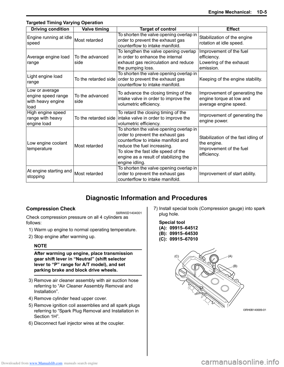
Targeted Timing Varying Operation
Diagnostic Information and Procedures
Compression CheckS6RW0D1404001
Check compression pressure on all 4 cylinders as
follows:
1) Warm up engine to normal operating temperature.
2) Stop engine after warming up.
NOTE
After warming up engine, place transmission
gear shift lever in “Neutral” (shift selector
lever to “P” range for A/T model), and set
parking brake and block drive wheels.
3) Remove air cleaner assembly with air suction hose
referring to “Air Cleaner Assembly Removal and
Installation”.
4) Remove cylinder head upper cover.
5) Remove ignition coil assemblies and all spark plugs
referring to “Spark Plug Removal and Installation in
Section 1H”.
6) Disconnect fuel injector wires at the coupler.7) Install special tools (Compression gauge) into spark
plug hole.
Special tool
(A): 09915–64512
(B): 09915–64530
(C): 09915–67010 Driving condition Valve timing Target of control Effect
Engine running at idle
speedMost retardedTo shorten the valve opening overlap in
order to prevent the exhaust gas
counterflow to intake manifold.Stabilization of the engine
rotation at idle speed.
Average engine load
rangeTo the advanced
sideTo lengthen the valve opening overlap
in order to enhance the internal
exhaust gas recirculation and reduce
the pumping loss.Improvement of the fuel
efficiency.
Lowering of the exhaust
emission.
Light engine load
rangeTo the retarded sideTo shorten the valve opening overlap in
order to prevent the exhaust gas
counterflow to intake manifold.Keeping of the engine stability.
Low or average
engine speed range
with heavy engine
loadTo the advanced
sideTo advance the closing timing of the
intake valve in order to improve the
volumetric efficiency.Improvement of generating the
engine torque at low and
average engine speed.
High engine speed
range with heavy
engine loadTo the retarded sideTo retard the closing timing of the
intake valve in order to improve the
volumetric efficiency.Improvement of generating the
engine power.
Low engine coolant
temperatureMost retardedTo shorten the valve opening overlap in
order to prevent the exhaust gas
counterflow to intake manifold and
reduce the fuel increasing.
To slow the fast idle speed of the
engine as a result of stabilizing the
engine idling.Stabilization of the fast idling of
the engine.
Improvement of the fuel
efficiency.
At engine starting and
stoppingMost retardedTo shorten the valve opening overlap in
order to prevent the exhaust gas
counterflow to intake manifold.Improvement of start ability.
(A)
(C)
(B)
I3RH0B140009-01
Page 295 of 1556
Downloaded from www.Manualslib.com manuals search engine Engine Mechanical: 1D-13
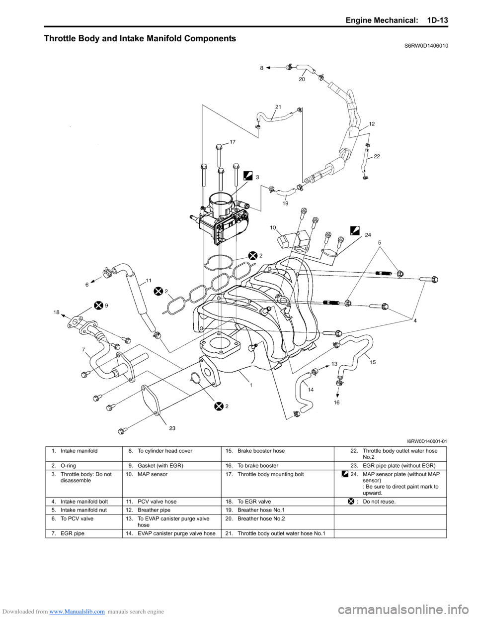
Throttle Body and Intake Manifold ComponentsS6RW0D1406010
I6RW0D140001-01
1. Intake manifold 8. To cylinder head cover 15. Brake booster hose 22. Throttle body outlet water hose
No.2
2. O-ring 9. Gasket (with EGR) 16. To brake booster 23. EGR pipe plate (without EGR)
3. Throttle body: Do not
disassemble10. MAP sensor 17. Throttle body mounting bolt 24. MAP sensor plate (without MAP
sensor)
: Be sure to direct paint mark to
upward.
4. Intake manifold bolt 11. PCV valve hose 18. To EGR valve : Do not reuse.
5. Intake manifold nut 12. Breather pipe 19. Breather hose No.1
6. To PCV valve 13. To EVAP canister purge valve
hose20. Breather hose No.2
7. EGR pipe 14. EVAP canister purge valve hose 21. Throttle body outlet water hose No.1
Page 296 of 1556
Downloaded from www.Manualslib.com manuals search engine 1D-14 Engine Mechanical:
Throttle Body On-Vehicle InspectionS6RW0D1406006
Check electric throttle body assembly referring to
“Throttle Valve Operation Check” and “Electric Throttle
Body Assembly Operation Check” under “Electric
Throttle Body Assembly On-Vehicle Inspection in
Section 1C”.
Electric Throttle Body Assembly Removal and
Installation
S6RW0D1406047
CAUTION!
Never disassemble electric throttle body.
Disassembly will spoil its original
performance. If faulty condition is found,
replace it with new one.
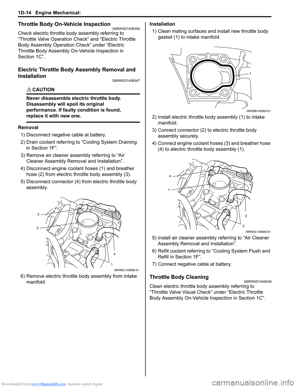
Removal
1) Disconnect negative cable at battery.
2) Drain coolant referring to “Cooling System Draining
in Section 1F”.
3) Remove air cleaner assembly referring to “Air
Cleaner Assembly Removal and Installation”.
4) Disconnect engine coolant hoses (1) and breather
hose (2) from electric throttle body assembly (3).
5) Disconnect connector (4) from electric throttle body
assembly.
6) Remove electric throttle body assembly from intake
manifold.Installation
1) Clean mating surfaces and install new throttle body
gasket (1) to intake manifold.
2) Install electric throttle body assembly (1) to intake
manifold.
3) Connect connector (2) to electric throttle body
assembly securely.
4) Connect engine coolant hoses (3) and breather hose
(4) to electric throttle body assembly (1).
5) Install air cleaner assembly referring to “Air Cleaner
Assembly Removal and Installation”.
6) Refill coolant referring to “Cooling System Flush and
Refill in Section 1F”.
7) Connect negative cable at battery.
Throttle Body CleaningS6RW0D1406048
Clean electric throttle body assembly referring to
“Throttle Valve Visual Check” under “Electric Throttle
Body Assembly On-Vehicle Inspection in Section 1C”.
2
4
3
1
I5RW0C140006-01
1
I4RS0B140005-01
4
2
1
3
I5RW0C140008-01
Page 297 of 1556
Downloaded from www.Manualslib.com manuals search engine Engine Mechanical: 1D-15
Intake Manifold Removal and InstallationS6RW0D1406011
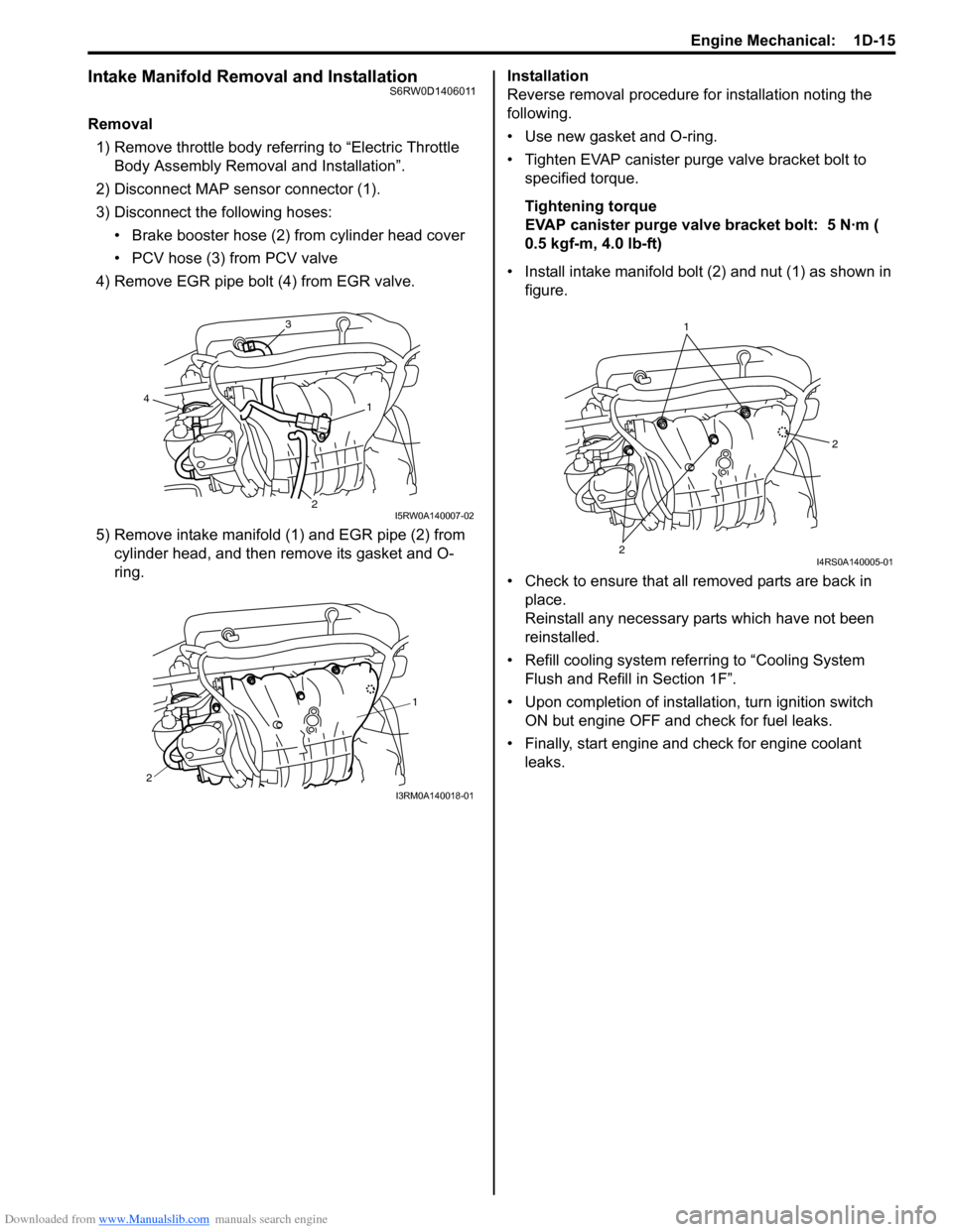
Removal
1) Remove throttle body referring to “Electric Throttle
Body Assembly Removal and Installation”.
2) Disconnect MAP sensor connector (1).
3) Disconnect the following hoses:
• Brake booster hose (2) from cylinder head cover
• PCV hose (3) from PCV valve
4) Remove EGR pipe bolt (4) from EGR valve.
5) Remove intake manifold (1) and EGR pipe (2) from
cylinder head, and then remove its gasket and O-
ring.Installation
Reverse removal procedure for installation noting the
following.
• Use new gasket and O-ring.
• Tighten EVAP canister purge valve bracket bolt to
specified torque.
Tightening torque
EVAP canister purge valve bracket bolt: 5 N·m (
0.5 kgf-m, 4.0 lb-ft)
• Install intake manifold bolt (2) and nut (1) as shown in
figure.
• Check to ensure that all removed parts are back in
place.
Reinstall any necessary parts which have not been
reinstalled.
• Refill cooling system referring to “Cooling System
Flush and Refill in Section 1F”.
• Upon completion of installation, turn ignition switch
ON but engine OFF and check for fuel leaks.
• Finally, start engine and check for engine coolant
leaks.
3
1
24
I5RW0A140007-02
1
2
I3RM0A140018-01
1
2
2
I4RS0A140005-01