oxygen SUZUKI SX4 2006 1.G Service Owner's Manual
[x] Cancel search | Manufacturer: SUZUKI, Model Year: 2006, Model line: SX4, Model: SUZUKI SX4 2006 1.GPages: 1556, PDF Size: 37.31 MB
Page 224 of 1556
Downloaded from www.Manualslib.com manuals search engine 1A-174 Engine General Information and Diagnosis:
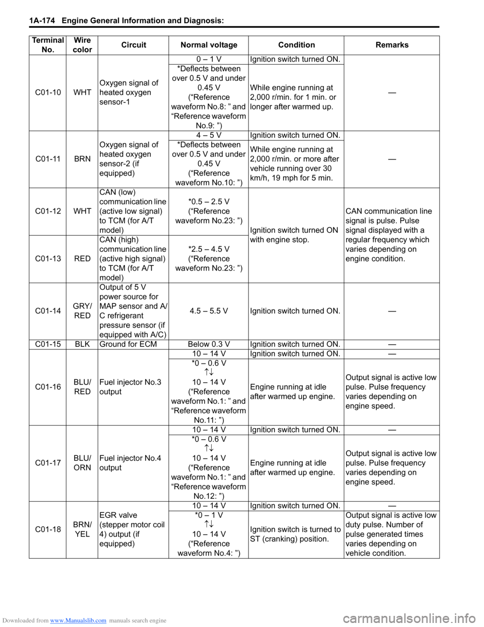
C01-10 WHTOxygen signal of
heated oxygen
sensor-10 – 1 V Ignition switch turned ON.
— *Deflects between
over 0.5 V and under
0.45 V
(“Reference
waveform No.8: ” and
“Reference waveform
No.9: ”)While engine running at
2,000 r/min. for 1 min. or
longer after warmed up.
C01-11 BRNOxygen signal of
heated oxygen
sensor-2 (if
equipped)4 – 5 V Ignition switch turned ON.
— *Deflects between
over 0.5 V and under
0.45 V
(“Reference
waveform No.10: ”)While engine running at
2,000 r/min. or more after
vehicle running over 30
km/h, 19 mph for 5 min.
C01-12 WHTCAN (low)
communication line
(active low signal)
to TCM (for A/T
model)*0.5 – 2.5 V
(“Reference
waveform No.23: ”)
Ignition switch turned ON
with engine stop.CAN communication line
signal is pulse. Pulse
signal displayed with a
regular frequency which
varies depending on
engine condition. C01-13 REDCAN (high)
communication line
(active high signal)
to TCM (for A/T
model)*2.5 – 4.5 V
(“Reference
waveform No.23: ”)
C01-14GRY/
REDOutput of 5 V
power source for
MAP sensor and A/
C refrigerant
pressure sensor (if
equipped with A/C)4.5 – 5.5 V Ignition switch turned ON. —
C01-15 BLK Ground for ECM Below 0.3 V Ignition switch turned ON. —
C01-16BLU/
REDFuel injector No.3
output10 – 14 V Ignition switch turned ON. —
*0 – 0.6 V
↑↓
10 – 14 V
(“Reference
waveform No.1: ” and
“Reference waveform
No.11: ”)Engine running at idle
after warmed up engine.Output signal is active low
pulse. Pulse frequency
varies depending on
engine speed.
C01-17BLU/
ORNFuel injector No.4
output10 – 14 V Ignition switch turned ON. —
*0 – 0.6 V
↑↓
10 – 14 V
(“Reference
waveform No.1: ” and
“Reference waveform
No.12: ”)Engine running at idle
after warmed up engine.Output signal is active low
pulse. Pulse frequency
varies depending on
engine speed.
C01-18BRN/
YELEGR valve
(stepper motor coil
4) output (if
equipped)10 – 14 V Ignition switch turned ON. —
*0 – 1 V
↑↓
10 – 14 V
(“Reference
waveform No.4: ”)Ignition switch is turned to
ST (cranking) position.Output signal is active low
duty pulse. Number of
pulse generated times
varies depending on
vehicle condition. Terminal
No.Wire
colorCircuit Normal voltage Condition Remarks
Page 226 of 1556

Downloaded from www.Manualslib.com manuals search engine 1A-176 Engine General Information and Diagnosis:
C01-34 — — — — —
C01-35 — — — — —
C01-36 — — — — —
C01-37 — — — — —
C01-38 — — — — —
C01-39 — — — — —
C01-40 WHTThrottle position
sensor (sub) signal1.57 – 1.90 VIgnition switch turned ON
and accelerator pedal at
idle position after warmed
up engine.
—
3.88 – 4.45 V
(“Reference
waveform No.29: ”)Ignition switch turned ON
and accelerator pedal at
full depressed position
after warmed up engine.
C01-41 GRYGround for shield
wire of TP sensor
circuitBelow 0.3 V Ignition switch turned ON. —
C01-42 BLKGround for throttle
position sensorBelow 0.3 V Ignition switch turned ON. —
C01-43 REDOutput for 5 V
power source of
throttle position
sensor4.5 – 5.5 V Ignition switch turned ON. —
C01-44 YELOutput of throttle
actuator0 – 1 VIgnition switch turned ON
and accelerator pedal at
idle position after warmed
up engine. Output signal is pulse.
Duty ratio varies
depending on throttle
valve and accelerator
pedal position. *0 – 1 V
↑↓
10 – 14 V
(“Reference
waveform No.26: ”
and “Reference
waveform No.27: ”)Ignition switch turned ON
and accelerator pedal at
full depressed position
after warmed up engine.
C01-45 BLUOutput of throttle
actuator0 – 1 VIgnition switch turned ON
and accelerator pedal at
full depressed position
after warmed up engine. Output signal is pulse.
Duty ratio varies
depending on throttle
valve and accelerator
pedal position. *0 – 1 V
↑↓
10 – 14 V
(“Reference
waveform No.26: ”
and “Reference
waveform No.27: ”)Ignition switch turned ON
and accelerator pedal at
idle position after warmed
up engine.
C01-46BLK/
REDHeater output of
heated oxygen
sensor-110 – 14 V Ignition switch turned ON. —
*0 – 2 V
↑↓
10 – 14 V
(“Reference
waveform No.8: ” and
“Reference waveform
No.9: ”)Engine running at idle
after warmed up engine.Output signal is active low
duty pulse. Duty ratio
varies depending on
engine condition.
C01-47RED/
BLUHeater output of
heated oxygen
sensor-2 (if
equipped)10 – 14 V Ignition switch turned ON.
— 0 – 1 V
(“Reference
waveform No.10: ”)Engine running at idle
after vehicle running over
30 km/h, 19 mph for 5 min. Terminal
No.Wire
colorCircuit Normal voltage Condition Remarks
Page 234 of 1556

Downloaded from www.Manualslib.com manuals search engine 1A-184 Engine General Information and Diagnosis:
Reference waveform No.8
Heated oxygen sensor-1 signal (1) with engine idling
Reference waveform No.9
Heated oxygen sensor-1 heater signal (2) with engine
idlingReference waveform No.10
Heated oxygen sensor-2 heater signal (4) with engine
idling
Measurement
terminalCH1: “C01-10” to “C01-57”
CH2: “C01-46” to “C01-58”
Oscilloscope
settingCH1: 500 mV/DIV, CH2: 20 V/DIV
TIME: 1 s/DIV
Measurement
condition• After warmed up to normal
operating temperature
• Engine at specified idle speed
2. Heated oxygen sensor-1 heater signal
Measurement
terminalCH1: “C01-10” to “C01-57”
CH2: “C01-46” to “C01-58”
Oscilloscope
settingCH1: 500 mV/DIV, CH2: 10 V/DIV
TIME: 200 ms/DIV
Measurement
condition• After warmed up to normal
operating temperature
• Engine at specified idle speed
1. Heated oxygen sensor-1 signal 4. ON signal
3. OFF signal 5. One duty cycle
I4RS0B110058-01
I4RS0B110059-01
Measurement
terminalCH1: “C01-11” to “C01-57”
CH2: “C01-47” to “C01-58”
Oscilloscope
settingCH1: 500 mV/DIV, CH2: 10 V/DIV
TIME: 2 s/DIV
Measurement
condition• After warmed up to normal
operating temperature
• Vehicle driving at 60 km/h (37
mph) for 10 min.
• Engine at specified idle speed
1. Heated oxygen sensor-2 signal upper limit
2. Heated oxygen sensor-2 signal lower limit
3. Normal waveform range
I4RS0B110060-01
Page 276 of 1556
Downloaded from www.Manualslib.com manuals search engine 1C-8 Engine Electrical Devices:
Heated Oxygen Sensor (HO2S-1 and HO2S-2)
Heater On-Vehicle Inspection (If Equipped)
S6RW0D1306010
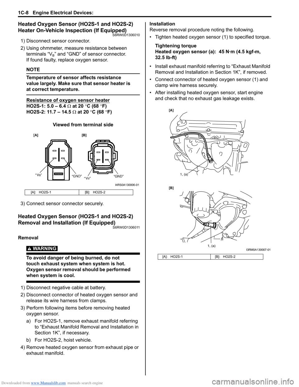
1) Disconnect sensor connector.
2) Using ohmmeter, measure resistance between
terminals “V
B” and “GND” of sensor connector.
If found faulty, replace oxygen sensor.
NOTE
Temperature of sensor affects resistance
value largely. Make sure that sensor heater is
at correct temperature.
Resistance of oxygen sensor heater
HO2S-1: 5.0 – 6.4 Ω at 20 °C (68 °F)
HO2S-2: 11.7 – 14.5 Ω at 20 °C (68 °F)
Viewed from terminal side
3) Connect sensor connector securely.
Heated Oxygen Sensor (HO2S-1 and HO2S-2)
Removal and Installation (If Equipped)
S6RW0D1306011
Removal
WARNING!
To avoid danger of being burned, do not
touch exhaust system when system is hot.
Oxygen sensor removal should be performed
when system is cool.
1) Disconnect negative cable at battery.
2) Disconnect connector of heated oxygen sensor and
release its wire harness from clamps.
3) Perform following items before removing heated
oxygen sensor.
a) For HO2S-1, remove exhaust manifold referring
to “Exhaust Manifold Removal and Installation in
Section 1K”, if necessary.
b) For HO2S-2, hoist vehicle.
4) Remove heated oxygen sensor from exhaust pipe or
exhaust manifold.Installation
Reverse removal procedure noting the following.
• Tighten heated oxygen sensor (1) to specified torque.
Tightening torque
Heated oxygen sensor (a): 45 N·m (4.5 kgf-m,
32.5 lb-ft)
• Install exhaust manifold referring to “Exhaust Manifold
Removal and Installation in Section 1K”, if removed.
• Connect connector of heated oxygen sensor (1) and
clamp wire harness securely.
• After installing heated oxygen sensor, start engine
and check that no exhaust gas leakage exists.
[A]: HO2S-1 [B]: HO2S-2
I4RS0A130006-01
[A]: HO2S-1 [B]: HO2S-2
[A]
[B]
1, (a)
1, (a)
I3RM0A130007-01
Page 282 of 1556
Downloaded from www.Manualslib.com manuals search engine 1C-14 Engine Electrical Devices:
Specifications
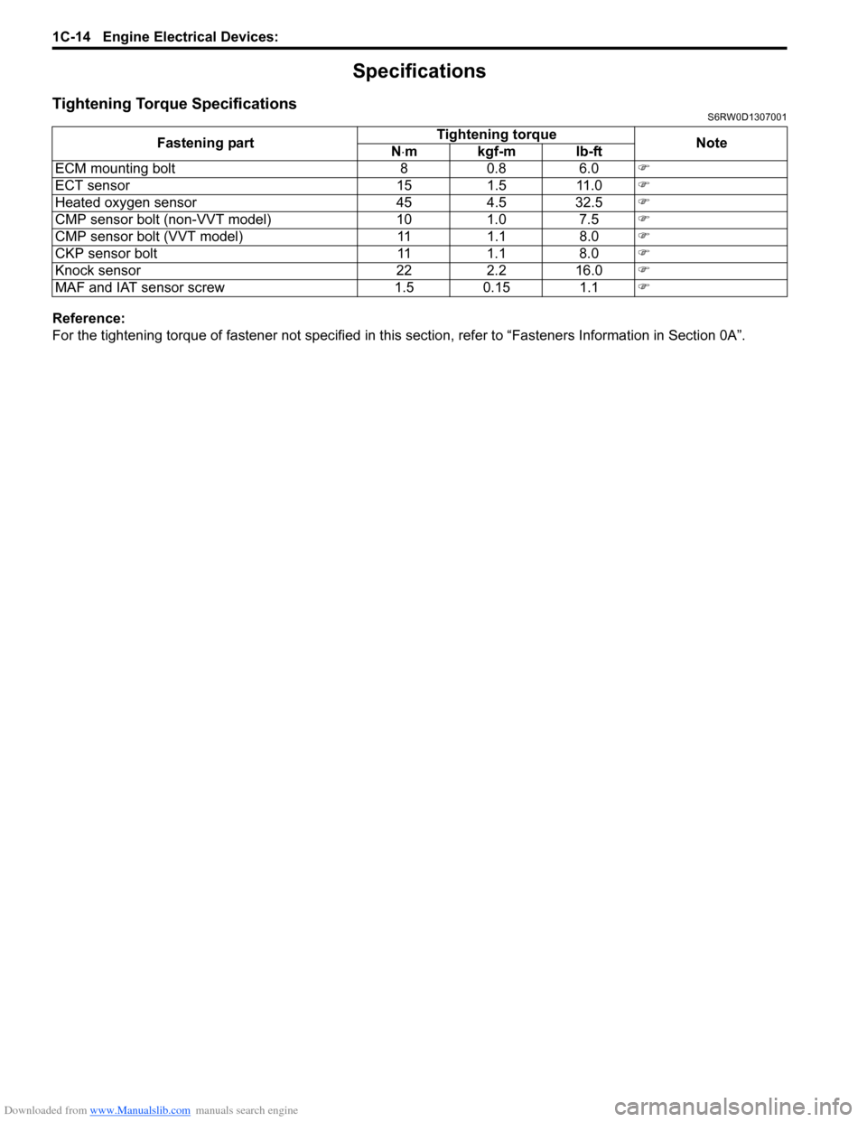
Tightening Torque SpecificationsS6RW0D1307001
Reference:
For the tightening torque of fastener not specified in this section, refer to “Fasteners Information in Section 0A”. Fastening partTightening torque
Note
N⋅mkgf-mlb-ft
ECM mounting bolt 8 0.8 6.0�)
ECT sensor 15 1.5 11.0�)
Heated oxygen sensor 45 4.5 32.5�)
CMP sensor bolt (non-VVT model) 10 1.0 7.5�)
CMP sensor bolt (VVT model) 11 1.1 8.0�)
CKP sensor bolt 11 1.1 8.0�)
Knock sensor 22 2.2 16.0�)
MAF and IAT sensor screw 1.5 0.15 1.1�)
Page 1179 of 1556
Downloaded from www.Manualslib.com manuals search engine Wiring Systems: 9A-12
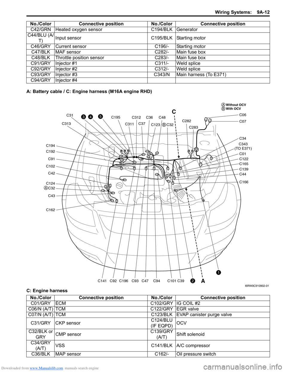
A: Battery cable / C: Engine harness (M16A engine RHD)
C: Engine harnessC42/GRN Heated oxygen sensor C194/BLK Generator
C44/BLU (A/
T)Input sensor C195/BLK Starting motor
C46/GRY Current sensor C196/- Starting motor
C47/BLK MAF sensor C282/- Main fuse box
C48/BLK Throttle position sensor C283/- Main fuse box
C91/GRY Injector #1 C311/- Weld splice
C92/GRY Injector #2 C312/- Weld splice
C93/GRY Injector #3 C343/N Main harness (To E371)
C94/GRY Injector #4 No./Color Connective position No./Color Connective position
C124
C32
C42
C102
C91
C192
C194
C43
C162
C141C196
C195
C93C94C101C39C92
C31
C311C313C312
C36C48
C37C123
C47C32C282
C283
C343
(TO E371)
C01
C34
C07
C06
C122
C165
C139
C44
C166
43
2
1
5C
A
Without OCV
With OCV A
A
B
B
I6RW0C910902-01
No./Color Connective position No./Color Connective position
C01/GRY ECM C102/GRY IG COIL #2
C06/N (A/T) TCM C122/GRY EGR valve
C07/N (A/T) TCM C123/BLK EVAP canister purge valve
C31/GRY CKP sensorC124/BLU
(IF EQPD)OCV
C32/BLK or
GRYCMP sensorC139/GRY
(A/T)Shift solenoid
C34/GRY
(A/T)VSS C141/BLK A/C compressor
C36/BLK MAP sensor C162/- Oil pressure switch
Page 1180 of 1556
Downloaded from www.Manualslib.com manuals search engine 9A-13 Wiring Systems:
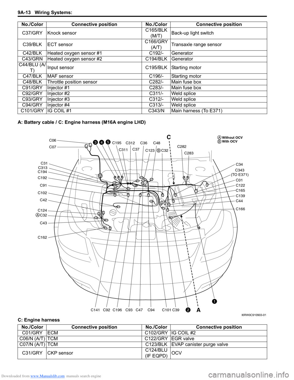
A: Battery cable / C: Engine harness (M16A engine LHD)
C: Engine harnessC37/GRY Knock sensorC165/BLK
(M/T)Back-up light switch
C39/BLK ECT sensorC166/GRY
(A/T)Transaxle range sensor
C42/BLK Heated oxygen sensor #1 C192/- Generator
C43/GRN Heated oxygen sensor #2 C194/BLK Generator
C44/BLU (A/
T)Input sensor C195/BLK Starting motor
C47/BLK MAF sensor C196/- Starting motor
C48/BLK Throttle position sensor C282/- Main fuse box
C91/GRY Injector #1 C283/- Main fuse box
C92/GRY Injector #2 C311/- Weld splice
C93/GRY Injector #3 C312/- Weld splice
C94/GRY Injector #4 C313/- Weld splice
C101/GRY IG COIL #1 C343/N Main harness (To E371)No./Color Connective position No./Color Connective position
C124
C32
C42
C102
C91
C192
C194
C43
C162
C141C196
C195
C93C94C101C39C92
C31
C311
C313C312
C36C48
C37C123
C47C32C282
C283
C343
(TO E371)
C01
C34
C07
C06
C122
C165
C139
C44
C166
43
2
1
5C
AWithout OCV
With OCV A
A
B
B
I6RW0C910903-01
No./Color Connective position No./Color Connective position
C01/GRY ECM C102/GRY IG COIL #2
C06/N (A/T) TCM C122/GRY EGR valve
C07/N (A/T) TCM C123/BLK EVAP canister purge valve
C31/GRY CKP sensorC124/BLU
(IF EQPD)OCV
Page 1181 of 1556
Downloaded from www.Manualslib.com manuals search engine Wiring Systems: 9A-14
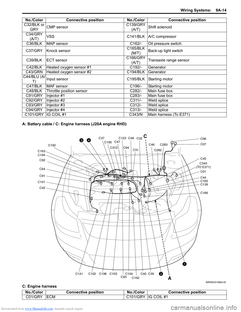
A: Battery cable / C: Engine harness (J20A engine RHD)
C: Engine harnessC32/BLK or
GRYCMP sensorC139/GRY
(A/T)Shift solenoid
C34/GRY
(A/T)VSS C141/BLK A/C compressor
C36/BLK MAP sensor C162/- Oil pressure switch
C37/GRY Knock sensorC165/BLK
(M/T)Back-up light switch
C39/BLK ECT sensorC166/GRY
(A/T)Transaxle range sensor
C42/BLK Heated oxygen sensor #1 C192/- Generator
C43/GRN Heated oxygen sensor #2 C194/BLK Generator
C44/BLU (A/
T)Input sensor C195/BLK Starting motor
C47/BLK MAF sensor C196/- Starting motor
C48/BLK Throttle position sensor C282/- Main fuse box
C91/GRY Injector #1 C283/- Main fuse box
C92/GRY Injector #2 C311/- Weld splice
C93/GRY Injector #3 C312/- Weld splice
C94/GRY Injector #4 C313/- Weld splice
C101/GRY IG COIL #1 C343/N Main harness (To E371)No./Color Connective position No./Color Connective position
C42
C101
C91
C64 C92
C194 C163
C141C102C196 C192
C195
C312
C93C104C103
C94C31C32
C40
C162
C39
C123C48C37
C47
C282
C283C46
C343
(TO E371)
C01
C45
C07
C06
C139 C44
C165
C166
3
2
1
4
A
C
I6RW0C910904-02
No./Color Connective position No./Color Connective position
C01/GRY ECM C101/GRY IG COIL #1
Page 1182 of 1556
Downloaded from www.Manualslib.com manuals search engine 9A-15 Wiring Systems:
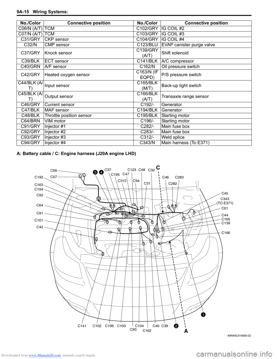
A: Battery cable / C: Engine harness (J20A engine LHD)C06/N (A/T) TCM C102/GRY IG COIL #2
C07/N (A/T) TCM C103/GRY IG COIL #3
C31/GRY CKP sensor C104/GRY IG COIL #4
C32/N CMP sensor C123/BLU EVAP canister purge valve
C37/GRY Knock sensorC139/GRY
(A/T)Shift solenoid
C39/BLK ECT sensor C141/BLK A/C compressor
C40/GRN A/F sensor C162/N Oil pressure switch
C42/GRY Heated oxygen sensorC163/N (IF
EQPD)P/S pressure switch
C44/BLK (A/
T)Input sensorC165/BLK
(M/T)Back-up light switch
C45/BLK (A/
T)Output sensorC166/BLK
(A/T)Transaxle range sensor
C46/GRY Current sensor C192/- Generator
C47/BLK MAF sensor C194/BLK Generator
C48/BLK Throttle position sensor C195/BLK Starting motor
C64/BRN VIM motor C196/- Starting motor
C91/GRY Injector #1 C282/- Main fuse box
C92/GRY Injector #2 C283/- Main fuse box
C93/GRY Injector #3 C312/- Weld splice
C94/GRY Injector #4 C343/N Main harness (To E371) No./Color Connective position No./Color Connective position
C42
C101
C91
C64 C92
C194 C163
C141C102C196 C192
C195
C312
C93C104C103
C94C31C32
C40
C162
C39
C123C48C37
C47
C282
C283C46
C343
(TO E371)
C01
C45
C07
C06
C139 C44
C165
C166
3
2
1
4C
A
I6RW0C910905-02
Page 1183 of 1556
Downloaded from www.Manualslib.com manuals search engine Wiring Systems: 9A-16
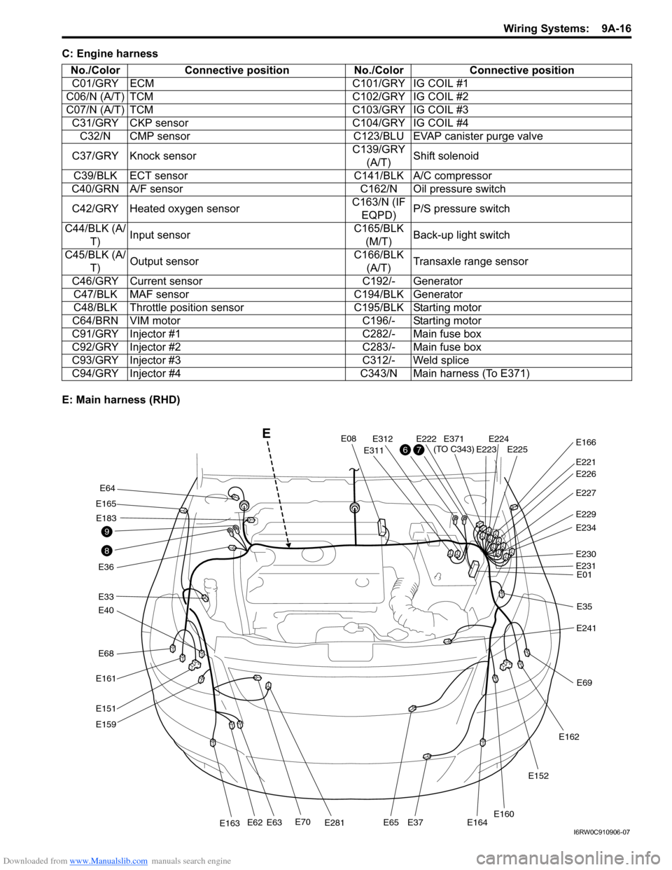
C: Engine harness
E: Main harness (RHD)No./Color Connective position No./Color Connective position
C01/GRY ECM C101/GRY IG COIL #1
C06/N (A/T) TCM C102/GRY IG COIL #2
C07/N (A/T) TCM C103/GRY IG COIL #3
C31/GRY CKP sensor C104/GRY IG COIL #4
C32/N CMP sensor C123/BLU EVAP canister purge valve
C37/GRY Knock sensorC139/GRY
(A/T)Shift solenoid
C39/BLK ECT sensor C141/BLK A/C compressor
C40/GRN A/F sensor C162/N Oil pressure switch
C42/GRY Heated oxygen sensorC163/N (IF
EQPD)P/S pressure switch
C44/BLK (A/
T)Input sensorC165/BLK
(M/T)Back-up light switch
C45/BLK (A/
T)Output sensorC166/BLK
(A/T)Transaxle range sensor
C46/GRY Current sensor C192/- Generator
C47/BLK MAF sensor C194/BLK Generator
C48/BLK Throttle position sensor C195/BLK Starting motor
C64/BRN VIM motor C196/- Starting motor
C91/GRY Injector #1 C282/- Main fuse box
C92/GRY Injector #2 C283/- Main fuse box
C93/GRY Injector #3 C312/- Weld splice
C94/GRY Injector #4 C343/N Main harness (To E371)
E68
E40
E33
E165
E36
E161
E151
E159
E70E281E163E62E63E65E37E164
E64
E183
E08
E311
E312E222E224E225E223
E221
E371
(TO C343)E166
E227
E229
E234
E230
E01
E35
E241
E69
E162
E152
E160
E231
E226
8
9
76
E
I6RW0C910906-07