AIR SUZUKI SX4 2006 1.G Service Repair Manual
[x] Cancel search | Manufacturer: SUZUKI, Model Year: 2006, Model line: SX4, Model: SUZUKI SX4 2006 1.GPages: 1556, PDF Size: 37.31 MB
Page 79 of 1556
Downloaded from www.Manualslib.com manuals search engine Engine General Information and Diagnosis: 1A-29
Troubleshooting
Step Action Yes No
1Scan tool check
1) Disconnect scan tool from DLC with ignition switch
turned OFF.
2) Check for proper connection to all terminals of scan tool
connector.
3) If OK, connect scan tool to another vehicle of this type
with ignition switch turned OFF.
4) Check communication between scan tool and ECM by
DTC check in ECM.
Is it possible to check DTC in ECM?Go to Step 2. Scan tool faulty. Refer
to its operator’s manual.
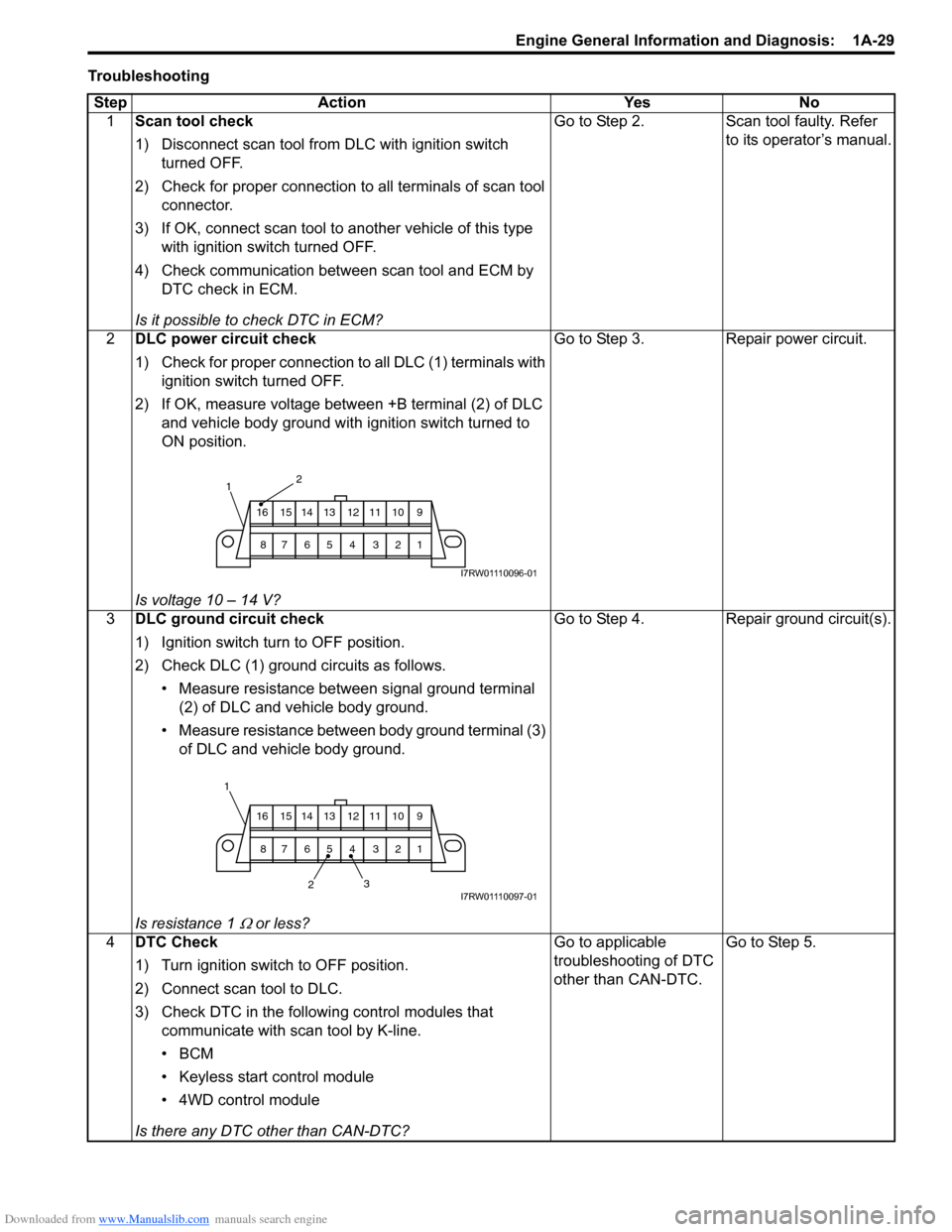
2DLC power circuit check
1) Check for proper connection to all DLC (1) terminals with
ignition switch turned OFF.
2) If OK, measure voltage between +B terminal (2) of DLC
and vehicle body ground with ignition switch turned to
ON position.
Is voltage 10 – 14 V?Go to Step 3. Repair power circuit.
3DLC ground circuit check
1) Ignition switch turn to OFF position.
2) Check DLC (1) ground circuits as follows.
• Measure resistance between signal ground terminal
(2) of DLC and vehicle body ground.
• Measure resistance between body ground terminal (3)
of DLC and vehicle body ground.
Is resistance 1
Ω or less?Go to Step 4. Repair ground circuit(s).
4DTC Check
1) Turn ignition switch to OFF position.
2) Connect scan tool to DLC.
3) Check DTC in the following control modules that
communicate with scan tool by K-line.
•BCM
• Keyless start control module
• 4WD control module
Is there any DTC other than CAN-DTC?Go to applicable
troubleshooting of DTC
other than CAN-DTC.Go to Step 5.
2
9 10 11 12 13 14 15 16
1 2 3 4 5 6 7 8
1
I7RW01110096-01
23 1
9 10 11 12 13 14 15 16
1 2 3 4 5 6 7 8
I7RW01110097-01
Page 80 of 1556
Downloaded from www.Manualslib.com manuals search engine 1A-30 Engine General Information and Diagnosis:
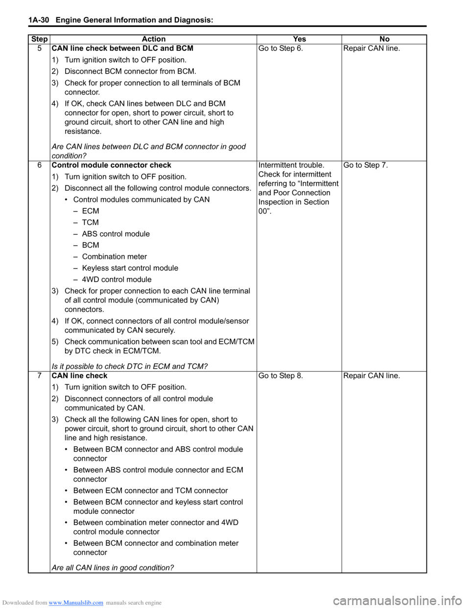
5CAN line check between DLC and BCM
1) Turn ignition switch to OFF position.
2) Disconnect BCM connector from BCM.
3) Check for proper connection to all terminals of BCM
connector.
4) If OK, check CAN lines between DLC and BCM
connector for open, short to power circuit, short to
ground circuit, short to other CAN line and high
resistance.
Are CAN lines between DLC and BCM connector in good
condition?Go to Step 6. Repair CAN line.
6Control module connector check
1) Turn ignition switch to OFF position.
2) Disconnect all the following control module connectors.
• Control modules communicated by CAN
–ECM
–TCM
– ABS control module
–BCM
– Combination meter
– Keyless start control module
– 4WD control module
3) Check for proper connection to each CAN line terminal
of all control module (communicated by CAN)
connectors.
4) If OK, connect connectors of all control module/sensor
communicated by CAN securely.
5) Check communication between scan tool and ECM/TCM
by DTC check in ECM/TCM.
Is it possible to check DTC in ECM and TCM?Intermittent trouble.
Check for intermittent
referring to “Intermittent
and Poor Connection
Inspection in Section
00”.Go to Step 7.
7CAN line check
1) Turn ignition switch to OFF position.
2) Disconnect connectors of all control module
communicated by CAN.
3) Check all the following CAN lines for open, short to
power circuit, short to ground circuit, short to other CAN
line and high resistance.
• Between BCM connector and ABS control module
connector
• Between ABS control module connector and ECM
connector
• Between ECM connector and TCM connector
• Between BCM connector and keyless start control
module connector
• Between combination meter connector and 4WD
control module connector
• Between BCM connector and combination meter
connector
Are all CAN lines in good condition?Go to Step 8. Repair CAN line. Step Action Yes No
Page 82 of 1556
Downloaded from www.Manualslib.com manuals search engine 1A-32 Engine General Information and Diagnosis:
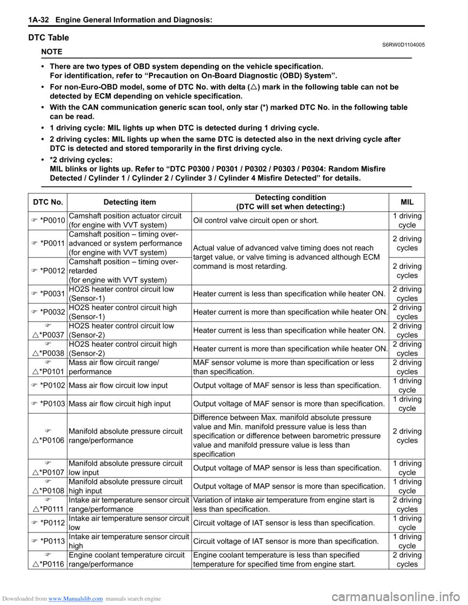
DTC TableS6RW0D1104005
NOTE
• There are two types of OBD system depending on the vehicle specification.
For identification, refer to “Precaution on On-Board Diagnostic (OBD) System”.
• For non-Euro-OBD model, some of DTC No. with delta (�U) mark in the following table can not be
detected by ECM depending on vehicle specification.
• With the CAN communication generic scan tool, only star (*) marked DTC No. in the following table
can be read.
• 1 driving cycle: MIL lights up when DTC is detected during 1 driving cycle.
• 2 driving cycles: MIL lights up when the same DTC is detected also in the next driving cycle after
DTC is detected and stored temporarily in the first driving cycle.
• *2 driving cycles:
MIL blinks or lights up. Refer to “DTC P0300 / P0301 / P0302 / P0303 / P0304: Random Misfire
Detected / Cylinder 1 / Cylinder 2 / Cylinder 3 / Cylinder 4 Misfire Detected” for details.
DTC No. Detecting itemDetecting condition
(DTC will set when detecting:)MIL
�) *P0010Camshaft position actuator circuit
(for engine with VVT system)Oil control valve circuit open or short.1 driving
cycle
�) *P0011Camshaft position – timing over-
advanced or system performance
(for engine with VVT system)Actual value of advanced valve timing does not reach
target value, or valve timing is advanced although ECM
command is most retarding.2 driving
cycles
�) *P0012Camshaft position – timing over-
retarded
(for engine with VVT system)2 driving
cycles
�) *P0031HO2S heater control circuit low
(Sensor-1)Heater current is less than specification while heater ON.2 driving
cycles
�) *P0032HO2S heater control circuit high
(Sensor-1)Heater current is more than specification while heater ON.2 driving
cycles
�)
�U*P0037HO2S heater control circuit low
(Sensor-2)Heater current is less than specification while heater ON.2 driving
cycles
�)
�U*P0038HO2S heater control circuit high
(Sensor-2)Heater current is more than specification while heater ON.2 driving
cycles
�)
�U*P0101Mass air flow circuit range/
performanceMAF sensor volume is more than specification or less
than specification.2 driving
cycles
�) *P0102 Mass air flow circuit low input Output voltage of MAF sensor is less than specification.1 driving
cycle
�) *P0103 Mass air flow circuit high input Output voltage of MAF sensor is more than specification.1 driving
cycle
�)
�U*P0106Manifold absolute pressure circuit
range/performanceDifference between Max. manifold absolute pressure
value and Min. manifold pressure value is less than
specification or difference between barometric pressure
value and manifold pressure value is less than
specification2 driving
cycles
�)
�U*P0107Manifold absolute pressure circuit
low inputOutput voltage of MAP sensor is less than specification.
1 driving
cycle
�)
�U*P0108Manifold absolute pressure circuit
high inputOutput voltage of MAP sensor is more than specification.1 driving
cycle
�)
�U* P 0 111Intake air temperature sensor circuit
range/performanceVariation of intake air temperature from engine start is
less than specification.2 driving
cycles
�) *P0112Intake air temperature sensor circuit
lowCircuit voltage of IAT sensor is less than specification.1 driving
cycle
�) *P0113Intake air temperature sensor circuit
highCircuit voltage of IAT sensor is more than specification.1 driving
cycle
�)
�U*P0116Engine coolant temperature circuit
range/performanceEngine coolant temperature is less than specified
temperature for specified time from engine start.2 driving
cycles
Page 86 of 1556
Downloaded from www.Manualslib.com manuals search engine 1A-36 Engine General Information and Diagnosis:
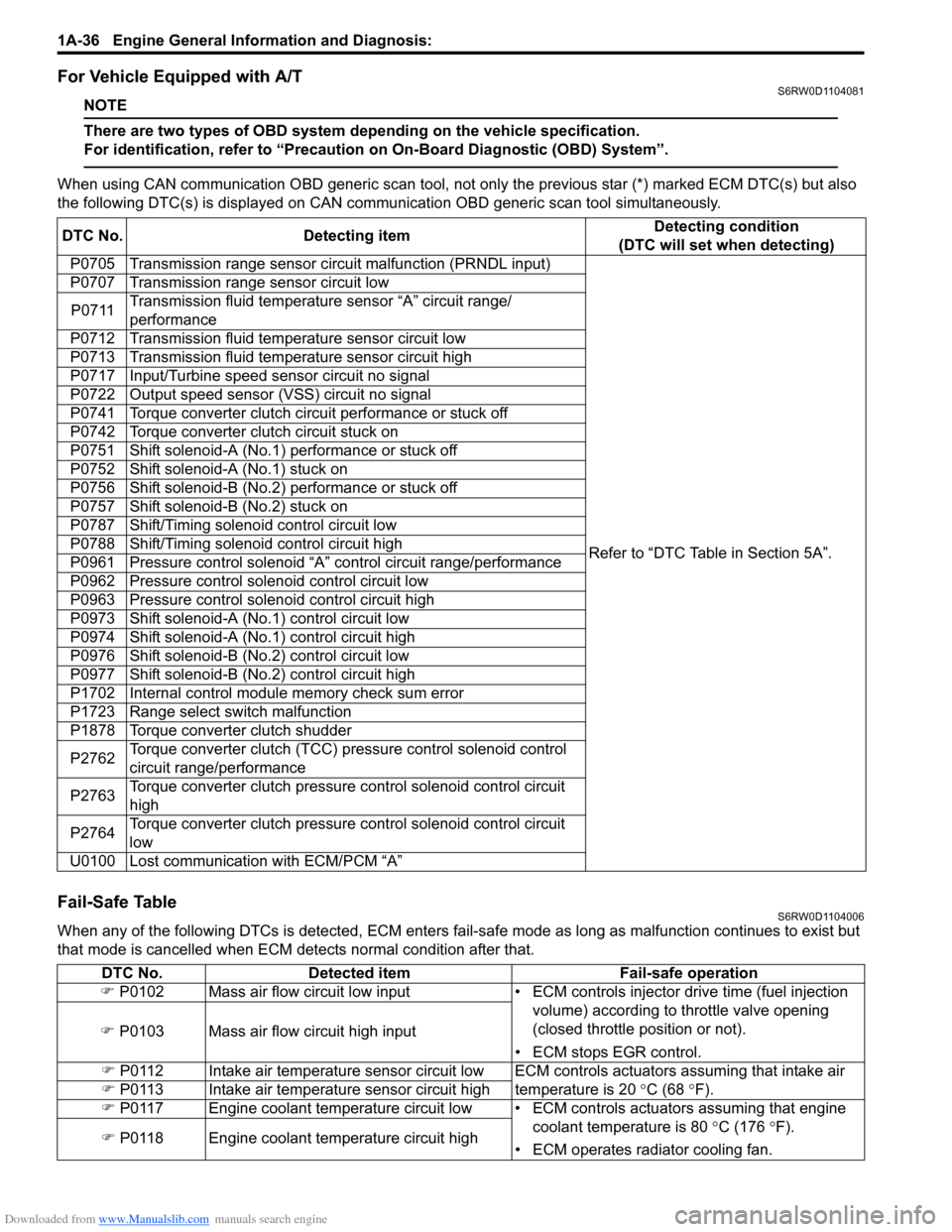
For Vehicle Equipped with A/TS6RW0D1104081
NOTE
There are two types of OBD system depending on the vehicle specification.
For identification, refer to “Precaution on On-Board Diagnostic (OBD) System”.
When using CAN communication OBD generic scan tool, not only the previous star (*) marked ECM DTC(s) but also
the following DTC(s) is displayed on CAN communication OBD generic scan tool simultaneously.
Fail-Safe TableS6RW0D1104006
When any of the following DTCs is detected, ECM enters fail-safe mode as long as malfunction continues to exist but
that mode is cancelled when ECM detects normal condition after that. DTC No. Detecting itemDetecting condition
(DTC will set when detecting)
P0705 Transmission range sensor circuit malfunction (PRNDL input)
Refer to “DTC Table in Section 5A”. P0707 Transmission range sensor circuit low
P0711Transmission fluid temperature sensor “A” circuit range/
performance
P0712 Transmission fluid temperature sensor circuit low
P0713 Transmission fluid temperature sensor circuit high
P0717 Input/Turbine speed sensor circuit no signal
P0722 Output speed sensor (VSS) circuit no signal
P0741 Torque converter clutch circuit performance or stuck off
P0742 Torque converter clutch circuit stuck on
P0751 Shift solenoid-A (No.1) performance or stuck off
P0752 Shift solenoid-A (No.1) stuck on
P0756 Shift solenoid-B (No.2) performance or stuck off
P0757 Shift solenoid-B (No.2) stuck on
P0787 Shift/Timing solenoid control circuit low
P0788 Shift/Timing solenoid control circuit high
P0961 Pressure control solenoid “A” control circuit range/performance
P0962 Pressure control solenoid control circuit low
P0963 Pressure control solenoid control circuit high
P0973 Shift solenoid-A (No.1) control circuit low
P0974 Shift solenoid-A (No.1) control circuit high
P0976 Shift solenoid-B (No.2) control circuit low
P0977 Shift solenoid-B (No.2) control circuit high
P1702 Internal control module memory check sum error
P1723 Range select switch malfunction
P1878 Torque converter clutch shudder
P2762Torque converter clutch (TCC) pressure control solenoid control
circuit range/performance
P2763Torque converter clutch pressure control solenoid control circuit
high
P2764Torque converter clutch pressure control solenoid control circuit
low
U0100 Lost communication with ECM/PCM “A”
DTC No. Detected item Fail-safe operation
�) P0102 Mass air flow circuit low input • ECM controls injector drive time (fuel injection
volume) according to throttle valve opening
(closed throttle position or not).
• ECM stops EGR control. �) P0103 Mass air flow circuit high input
�) P0112 Intake air temperature sensor circuit low ECM controls actuators assuming that intake air
temperature is 20 °C (68 °F). �) P0113 Intake air temperature sensor circuit high
�) P0117 Engine coolant temperature circuit low • ECM controls actuators assuming that engine
coolant temperature is 80 °C (176 °F).
• ECM operates radiator cooling fan. �) P0118 Engine coolant temperature circuit high
Page 87 of 1556
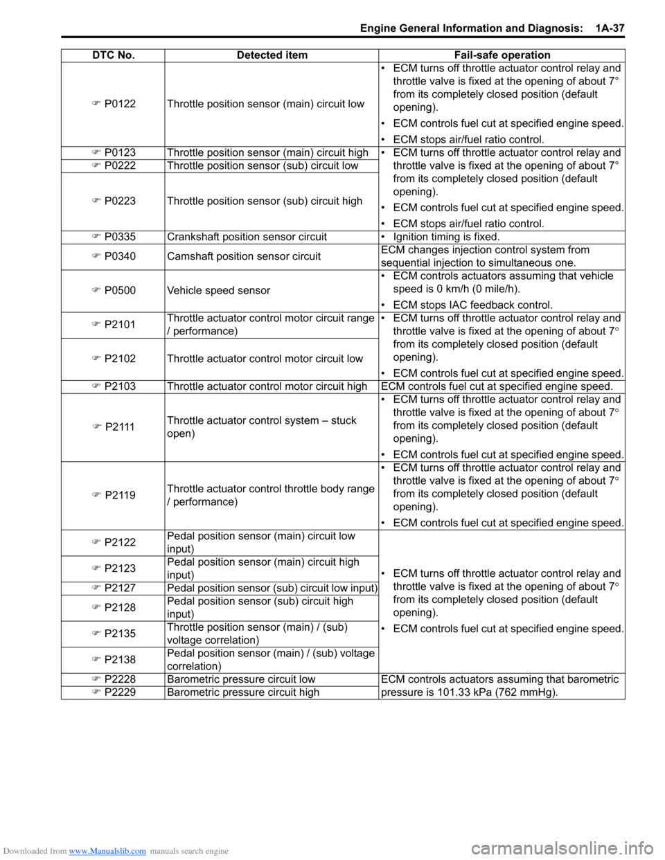
Downloaded from www.Manualslib.com manuals search engine Engine General Information and Diagnosis: 1A-37
�) P0122 Throttle position sensor (main) circuit low• ECM turns off throttle actuator control relay and
throttle valve is fixed at the opening of about 7°
from its completely closed position (default
opening).
• ECM controls fuel cut at specified engine speed.
• ECM stops air/fuel ratio control.
�) P0123 Throttle position sensor (main) circuit high• ECM turns off throttle actuator control relay and
throttle valve is fixed at the opening of about 7°
from its completely closed position (default
opening).
• ECM controls fuel cut at specified engine speed.
• ECM stops air/fuel ratio control. �) P0222 Throttle position sensor (sub) circuit low
�) P0223 Throttle position sensor (sub) circuit high
�) P0335 Crankshaft position sensor circuit • Ignition timing is fixed.
�) P0340 Camshaft position sensor circuitECM changes injection control system from
sequential injection to simultaneous one.
�) P0500 Vehicle speed sensor• ECM controls actuators assuming that vehicle
speed is 0 km/h (0 mile/h).
• ECM stops IAC feedback control.
�) P2101Throttle actuator control motor circuit range
/ performance)• ECM turns off throttle actuator control relay and
throttle valve is fixed at the opening of about 7°
from its completely closed position (default
opening).
• ECM controls fuel cut at specified engine speed. �) P2102 Throttle actuator control motor circuit low
�) P2103 Throttle actuator control motor circuit highECM controls fuel cut at specified engine speed.
�) P 2 111Throttle actuator control system – stuck
open)• ECM turns off throttle actuator control relay and
throttle valve is fixed at the opening of about 7°
from its completely closed position (default
opening).
• ECM controls fuel cut at specified engine speed.
�) P2119Throttle actuator control throttle body range
/ performance)• ECM turns off throttle actuator control relay and
throttle valve is fixed at the opening of about 7°
from its completely closed position (default
opening).
• ECM controls fuel cut at specified engine speed.
�) P2122Pedal position sensor (main) circuit low
input)
• ECM turns off throttle actuator control relay and
throttle valve is fixed at the opening of about 7°
from its completely closed position (default
opening).
• ECM controls fuel cut at specified engine speed. �) P2123Pedal position sensor (main) circuit high
input)
�) P2127 Pedal position sensor (sub) circuit low input)
�) P2128Pedal position sensor (sub) circuit high
input)
�) P2135Throttle position sensor (main) / (sub)
voltage correlation)
�) P2138Pedal position sensor (main) / (sub) voltage
correlation)
�) P2228 Barometric pressure circuit low ECM controls actuators assuming that barometric
pressure is 101.33 kPa (762 mmHg). �) P2229 Barometric pressure circuit high DTC No. Detected item Fail-safe operation
Page 88 of 1556
Downloaded from www.Manualslib.com manuals search engine 1A-38 Engine General Information and Diagnosis:
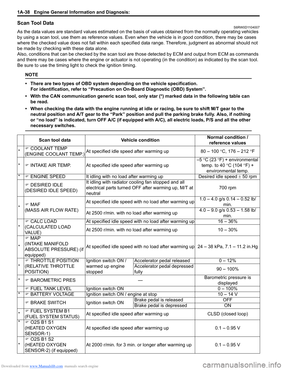
Scan Tool DataS6RW0D1104007
As the data values are standard values estimated on the basis of values obtained from the normally operating vehicles
by using a scan tool, use them as reference values. Even when the vehicle is in good condition, there may be cases
where the checked value does not fall within each specified data range. Therefore, judgment as abnormal should not
be made by checking with these data alone.
Also, conditions that can be checked by the scan tool are those detected by ECM and output from ECM as commands
and there may be cases where the engine or actuator is not operating (in the condition) as indicated by the scan tool.
Be sure to use the timing light to check the ignition timing.
NOTE
• There are two types of OBD system depending on the vehicle specification.
For identification, refer to “Precaution on On-Board Diagnostic (OBD) System”.
• With the CAN communication generic scan tool, only star (*) marked data in the following table can
be read.
• When checking the data with the engine running at idle or racing, be sure to shift M/T gear to the
neutral position and A/T gear to the “Park” position and pull the parking brake fully. Also, if nothing
or “no load” is indicated, turn OFF A/C (if equipped with A/C), all electric loads, P/S and all the other
necessary switches.
Scan tool data Vehicle conditionNormal condition /
reference values
*�) COOLANT TEMP
(ENGINE COOLANT TEMP.)At specified idle speed after warming up 80 – 100 °C, 176 – 212 °F
*�) INTAKE AIR TEMP. At specified idle speed after warming up–5 °C (23 °F) + environmental
temp. to 40 °C (104 °F) +
environmental temp.
*�) ENGINE SPEED It idling with no load after warming up Desired idle speed ± 50 rpm
�) DESIRED IDLE
(DESIRED IDLE SPEED)It idling with radiator cooling fan stopped and all
electrical parts turned OFF after warming up, M/T at
neutral700 rpm
*�) MAF
(MASS AIR FLOW RATE)At specified idle speed with no load after warming up1.0 – 4.0 g/s 0.14 – 0.52 lb/
min.
At 2500 r/min. with no load after warming up4.0 – 9.0 g/s 0.53 – 1.58 lb/
min.
*�) CALC LOAD
(CALCULATED LOAD
VA L U E )At specified idle speed with no load after warming up 16 – 36%
At 2500 r/min. with no load after warming up 10 – 30%
*�) MAP
(INTAKE MANIFOLD
ABSOLUTE PRESSURE) (if
equipped)At specified idle speed with no load after warming up 24 – 38 kPa, 7.1 – 11.2 in.Hg
*�) THROTTLE POSITION
(RELATIVE THROTTLE
POSITION)Ignition switch ON /
warmed up engine
stoppedAccelerator pedal released 0 – 12%
Accelerator pedal depressed
fully90 – 100%
*�) BAROMETRIC PRES —Barometric pressure is
displayed
�) FUEL TANK LEVEL Ignition switch ON 0 – 100%
*�) BATTERY VOLTAGE Ignition switch ON / engine at stop 10 – 14 V
�) BRAKE SWITCH Ignition switch ONBrake pedal is released OFF
Brake pedal is depressed ON
*�) FUEL SYSTEM B1
(FUEL SYSTEM STATUS)At specified idle speed after warming up CLSD (closed loop)
*�) O2S B1 S1
(HEATED OXYGEN
SENSOR-1)At specified idle speed after warming up 0.1 – 0.95 V
*�)
O2S B1 S2
(HEATED OXYGEN
SENSOR-2) (if equipped)At 2000 r/min. for 3 min. or longer after warming up 0.1 – 0.95 V
Page 90 of 1556
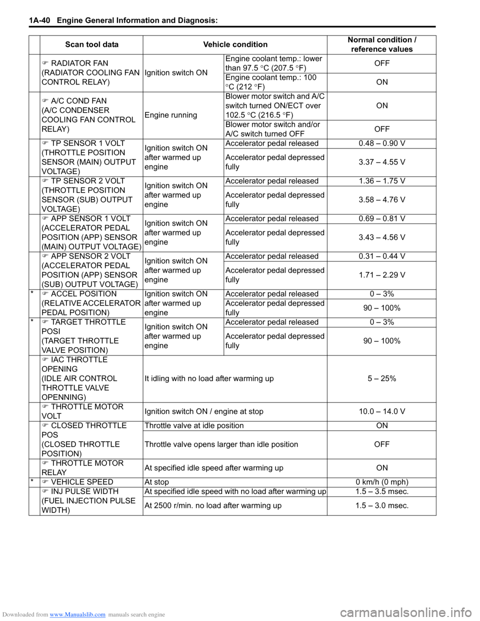
Downloaded from www.Manualslib.com manuals search engine 1A-40 Engine General Information and Diagnosis:
�) RADIATOR FAN
(RADIATOR COOLING FAN
CONTROL RELAY)Ignition switch ONEngine coolant temp.: lower
than 97.5 °C (207.5 °F)OFF
Engine coolant temp.: 100
°C (212 °F)ON
�) A/C COND FAN
(A/C CONDENSER
COOLING FAN CONTROL
RELAY)Engine runningBlower motor switch and A/C
switch turned ON/ECT over
102.5 °C (216.5 °F)ON
Blower motor switch and/or
A/C switch turned OFFOFF
�) TP SENSOR 1 VOLT
(THROTTLE POSITION
SENSOR (MAIN) OUTPUT
VOLTAGE)Ignition switch ON
after warmed up
engineAccelerator pedal released 0.48 – 0.90 V
Accelerator pedal depressed
fully3.37 – 4.55 V
�) TP SENSOR 2 VOLT
(THROTTLE POSITION
SENSOR (SUB) OUTPUT
VOLTAGE)Ignition switch ON
after warmed up
engineAccelerator pedal released 1.36 – 1.75 V
Accelerator pedal depressed
fully3.58 – 4.76 V
�) APP SENSOR 1 VOLT
(ACCELERATOR PEDAL
POSITION (APP) SENSOR
(MAIN) OUTPUT VOLTAGE)Ignition switch ON
after warmed up
engineAccelerator pedal released 0.69 – 0.81 V
Accelerator pedal depressed
fully3.43 – 4.56 V
�) APP SENSOR 2 VOLT
(ACCELERATOR PEDAL
POSITION (APP) SENSOR
(SUB) OUTPUT VOLTAGE)Ignition switch ON
after warmed up
engineAccelerator pedal released 0.31 – 0.44 V
Accelerator pedal depressed
fully1.71 – 2.29 V
*�) ACCEL POSITION
(RELATIVE ACCELERATOR
PEDAL POSITION)Ignition switch ON
after warmed up
engineAccelerator pedal released 0 – 3%
Accelerator pedal depressed
fully90 – 100%
*�) TARGET THROTTLE
POSI
(TARGET THROTTLE
VALVE POSITION)Ignition switch ON
after warmed up
engineAccelerator pedal released 0 – 3%
Accelerator pedal depressed
fully90 – 100%
�) IAC THROTTLE
OPENING
(IDLE AIR CONTROL
THROTTLE VALVE
OPENNING)It idling with no load after warming up 5 – 25%
�) THROTTLE MOTOR
VOLTIgnition switch ON / engine at stop 10.0 – 14.0 V
�) CLOSED THROTTLE
POS
(CLOSED THROTTLE
POSITION)Throttle valve at idle position ON
Throttle valve opens larger than idle position OFF
�) THROTTLE MOTOR
RELAYAt specified idle speed after warming up ON
*�) VEHICLE SPEED At stop 0 km/h (0 mph)
�) INJ PULSE WIDTH
(FUEL INJECTION PULSE
WIDTH)At specified idle speed with no load after warming up 1.5 – 3.5 msec.
At 2500 r/min. no load after warming up 1.5 – 3.0 msec. Scan tool data Vehicle conditionNormal condition /
reference values
Page 91 of 1556
Downloaded from www.Manualslib.com manuals search engine Engine General Information and Diagnosis: 1A-41
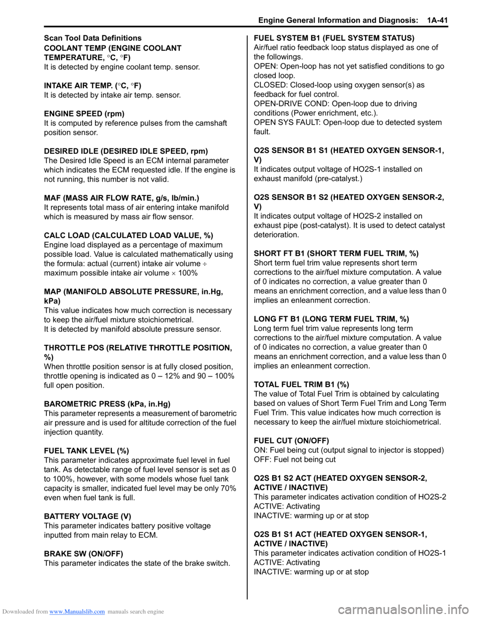
Scan Tool Data Definitions
COOLANT TEMP (ENGINE COOLANT
TEMPERATURE, °C, °F)
It is detected by engine coolant temp. sensor.
INTAKE AIR TEMP. (°C, °F)
It is detected by intake air temp. sensor.
ENGINE SPEED (rpm)
It is computed by reference pulses from the camshaft
position sensor.
DESIRED IDLE (DESIRED IDLE SPEED, rpm)
The Desired Idle Speed is an ECM internal parameter
which indicates the ECM requested idle. If the engine is
not running, this number is not valid.
MAF (MASS AIR FLOW RATE, g/s, lb/min.)
It represents total mass of air entering intake manifold
which is measured by mass air flow sensor.
CALC LOAD (CALCULATED LOAD VALUE, %)
Engine load displayed as a percentage of maximum
possible load. Value is calculated mathematically using
the formula: actual (current) intake air volume ÷
maximum possible intake air volume × 100%
MAP (MANIFOLD ABSOLUTE PRESSURE, in.Hg,
kPa)
This value indicates how much correction is necessary
to keep the air/fuel mixture stoichiometrical.
It is detected by manifold absolute pressure sensor.
THROTTLE POS (RELATIVE THROTTLE POSITION,
%)
When throttle position sensor is at fully closed position,
throttle opening is indicated as 0 – 12% and 90 – 100%
full open position.
BAROMETRIC PRESS (kPa, in.Hg)
This parameter represents a measurement of barometric
air pressure and is used for altitude correction of the fuel
injection quantity.
FUEL TANK LEVEL (%)
This parameter indicates approximate fuel level in fuel
tank. As detectable range of fuel level sensor is set as 0
to 100%, however, with some models whose fuel tank
capacity is smaller, indicated fuel level may be only 70%
even when fuel tank is full.
BATTERY VOLTAGE (V)
This parameter indicates battery positive voltage
inputted from main relay to ECM.
BRAKE SW (ON/OFF)
This parameter indicates the state of the brake switch.FUEL SYSTEM B1 (FUEL SYSTEM STATUS)
Air/fuel ratio feedback loop status displayed as one of
the followings.
OPEN: Open-loop has not yet satisfied conditions to go
closed loop.
CLOSED: Closed-loop using oxygen sensor(s) as
feedback for fuel control.
OPEN-DRIVE COND: Open-loop due to driving
conditions (Power enrichment, etc.).
OPEN SYS FAULT: Open-loop due to detected system
fault.
O2S SENSOR B1 S1 (HEATED OXYGEN SENSOR-1,
V)
It indicates output voltage of HO2S-1 installed on
exhaust manifold (pre-catalyst.)
O2S SENSOR B1 S2 (HEATED OXYGEN SENSOR-2,
V)
It indicates output voltage of HO2S-2 installed on
exhaust pipe (post-catalyst). It is used to detect catalyst
deterioration.
SHORT FT B1 (SHORT TERM FUEL TRIM, %)
Short term fuel trim value represents short term
corrections to the air/fuel mixture computation. A value
of 0 indicates no correction, a value greater than 0
means an enrichment correction, and a value less than 0
implies an enleanment correction.
LONG FT B1 (LONG TERM FUEL TRIM, %)
Long term fuel trim value represents long term
corrections to the air/fuel mixture computation. A value
of 0 indicates no correction, a value greater than 0
means an enrichment correction, and a value less than 0
implies an enleanment correction.
TOTAL FUEL TRIM B1 (%)
The value of Total Fuel Trim is obtained by calculating
based on values of Short Term Fuel Trim and Long Term
Fuel Trim. This value indicates how much correction is
necessary to keep the air/fuel mixture stoichiometrical.
FUEL CUT (ON/OFF)
ON: Fuel being cut (output signal to injector is stopped)
OFF: Fuel not being cut
O2S B1 S2 ACT (HEATED OXYGEN SENSOR-2,
ACTIVE / INACTIVE)
This parameter indicates activation condition of HO2S-2
ACTIVE: Activating
INACTIVE: warming up or at stop
O2S B1 S1 ACT (HEATED OXYGEN SENSOR-1,
ACTIVE / INACTIVE)
This parameter indicates activation condition of HO2S-1
ACTIVE: Activating
INACTIVE: warming up or at stop
Page 92 of 1556
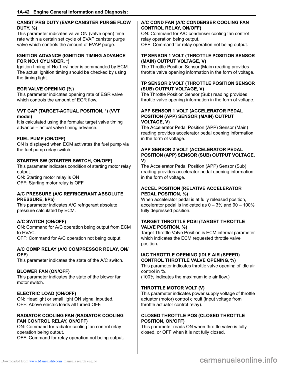
Downloaded from www.Manualslib.com manuals search engine 1A-42 Engine General Information and Diagnosis:
CANIST PRG DUTY (EVAP CANISTER PURGE FLOW
DUTY, %)
This parameter indicates valve ON (valve open) time
rate within a certain set cycle of EVAP canister purge
valve which controls the amount of EVAP purge.
IGNITION ADVANCE (IGNITION TIMING ADVANCE
FOR NO.1 CYLINDER, °)
Ignition timing of No.1 cylinder is commanded by ECM.
The actual ignition timing should be checked by using
the timing light.
EGR VALVE OPENING (%)
This parameter indicates opening rate of EGR valve
which controls the amount of EGR flow.
VVT GAP (TARGET-ACTUAL POSITION, °) (VVT
model)
It is calculated using the formula: target valve timing
advance – actual valve timing advance.
FUEL PUMP (ON/OFF)
ON is displayed when ECM activates the fuel pump via
the fuel pump relay switch.
STARTER SW (STARTER SWITCH, ON/OFF)
This parameter indicates condition of starting motor relay
output.
ON: Starting motor relay is ON
OFF: Starting motor relay is OFF
A/C PRESSURE (A/C REFRIGERANT ABSOLUTE
PRESSURE, kPa)
This parameter indicates A/C refrigerant absolute
pressure calculated by ECM.
A/C SWITCH (ON/OFF)
ON: Command for A/C operation being output from ECM
to HVAC.
OFF: Command for A/C operation not being output.
A/C COMP RELAY (A/C COMPRESSOR RELAY, ON/
OFF)
This parameter indicates the state of the A/C switch.
BLOWER FAN (ON/OFF)
This parameter indicates the state of the blower fan
motor switch.
ELECTRIC LOAD (ON/OFF)
ON: Headlight or small light ON signal inputted.
OFF: Above electric loads all turned OFF.
RADIATOR COOLING FAN (RADIATOR COOLING
FAN CONTROL RELAY, ON/OFF)
ON: Command for radiator cooling fan control relay
operation being output.
OFF: Command for relay operation not being output.A/C COND FAN (A/C CONDENSER COOLING FAN
CONTROL RELAY, ON/OFF)
ON: Command for A/C condenser cooling fan control
relay operation being output.
OFF: Command for relay operation not being output.
TP SENSOR 1 VOLT (THROTTLE POSITION SENSOR
(MAIN) OUTPUT VOLTAGE, V)
The Throttle Position Sensor (Main) reading provides
throttle valve opening information in the form of voltage.
TP SENSOR 2 VOLT (THROTTLE POSITION SENSOR
(SUB) OUTPUT VOLTAGE, V)
The Throttle Position Sensor (Sub) reading provides
throttle valve opening information in the form of voltage.
APP SENSOR 1 VOLT (ACCELERATOR PEDAL
POSITION (APP) SENSOR (MAIN) OUTPUT
VOLTAGE, V)
The Accelerator Pedal Position (APP) Sensor (Main)
reading provides accelerator pedal opening information
in the form of voltage.
APP SENSOR 2 VOLT (ACCELERATOR PEDAL
POSITION (APP) SENSOR (SUB) OUTPUT VOLTAGE,
V)
The Accelerator Pedal Position (APP) Sensor (Sub)
reading provides accelerator pedal opening information
in the form of voltage.
ACCEL POSITION (RELATIVE ACCELERATOR
PEDAL POSITION, %)
When accelerator pedal is at fully released position,
accelerator pedal is indicated as 0 – 3% and 90 – 100%
fully depressed position.
TARGET THROTTLE POSI (TARGET THROTTLE
VALVE POSITION, %)
Target Throttle Valve Position is ECM internal parameter
which indicates the ECM requested throttle valve
position.
IAC THROTTLE OPENING (IDLE AIR (SPEED)
CONTROL THROTTLE VALVE OPENING, %)
This parameter indicates throttle valve opening of idle air
control in %.
(100% indicates the maximum idle air flow.)
THROTTLE MOTOR VOLT (V)
This parameter indicates power supply voltage of throttle
actuator (motor) control circuit (input voltage from
throttle actuator control relay).
CLOSED THROTTLE POS (CLOSED THROTTLE
POSITION, ON/OFF)
This parameter reads ON when throttle valve is fully
closed, or OFF when it is not fully closed.
Page 93 of 1556
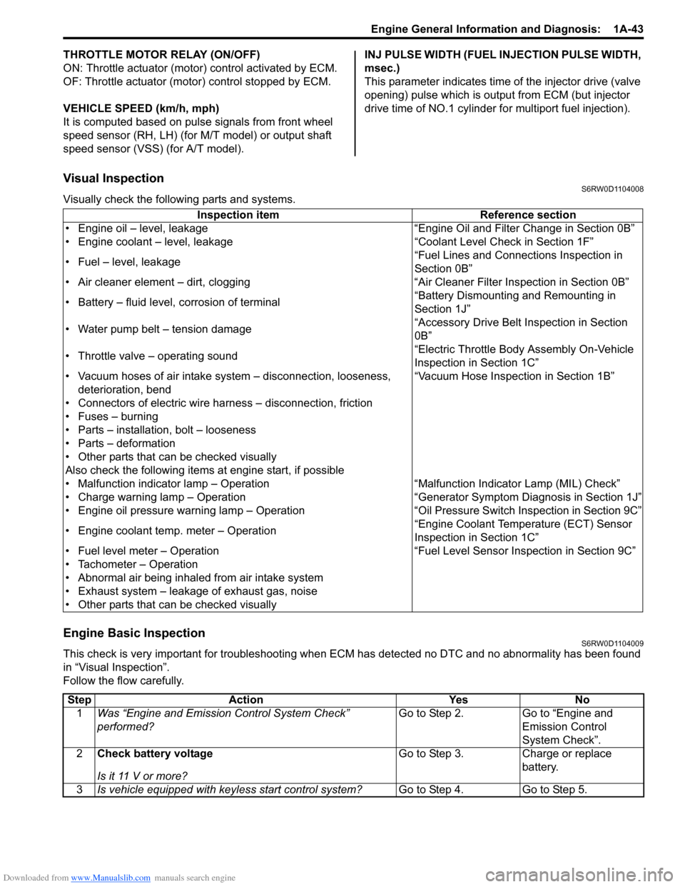
Downloaded from www.Manualslib.com manuals search engine Engine General Information and Diagnosis: 1A-43
THROTTLE MOTOR RELAY (ON/OFF)
ON: Throttle actuator (motor) control activated by ECM.
OF: Throttle actuator (motor) control stopped by ECM.
VEHICLE SPEED (km/h, mph)
It is computed based on pulse signals from front wheel
speed sensor (RH, LH) (for M/T model) or output shaft
speed sensor (VSS) (for A/T model).INJ PULSE WIDTH (FUEL INJECTION PULSE WIDTH,
msec.)
This parameter indicates time of the injector drive (valve
opening) pulse which is output from ECM (but injector
drive time of NO.1 cylinder for multiport fuel injection).
Visual InspectionS6RW0D1104008
Visually check the following parts and systems.
Engine Basic InspectionS6RW0D1104009
This check is very important for troubleshooting when ECM has detected no DTC and no abnormality has been found
in “Visual Inspection”.
Follow the flow carefully.Inspection item Reference section
• Engine oil – level, leakage “Engine Oil and Filter Change in Section 0B”
• Engine coolant – level, leakage “Coolant Level Check in Section 1F”
• Fuel – level, leakage“Fuel Lines and Connections Inspection in
Section 0B”
• Air cleaner element – dirt, clogging “Air Cleaner Filter Inspection in Section 0B”
• Battery – fluid level, corrosion of terminal“Battery Dismounting and Remounting in
Section 1J”
• Water pump belt – tension damage“Accessory Drive Belt Inspection in Section
0B”
• Throttle valve – operating sound“Electric Throttle Body Assembly On-Vehicle
Inspection in Section 1C”
• Vacuum hoses of air intake system – disconnection, looseness,
deterioration, bend“Vacuum Hose Inspection in Section 1B”
• Connectors of electric wire harness – disconnection, friction
• Fuses – burning
• Parts – installation, bolt – looseness
• Parts – deformation
• Other parts that can be checked visually
Also check the following items at engine start, if possible
• Malfunction indicator lamp – Operation “Malfunction Indicator Lamp (MIL) Check”
• Charge warning lamp – Operation “Generator Symptom Diagnosis in Section 1J”
• Engine oil pressure warning lamp – Operation “Oil Pressure Switch Inspection in Section 9C”
• Engine coolant temp. meter – Operation“Engine Coolant Temperature (ECT) Sensor
Inspection in Section 1C”
• Fuel level meter – Operation “Fuel Level Sensor Inspection in Section 9C”
• Tachometer – Operation
• Abnormal air being inhaled from air intake system
• Exhaust system – leakage of exhaust gas, noise
• Other parts that can be checked visually
Step Action Yes No
1Was “Engine and Emission Control System Check”
performed?Go to Step 2. Go to “Engine and
Emission Control
System Check”.
2Check battery voltage
Is it 11 V or more?Go to Step 3. Charge or replace
battery.
3Is vehicle equipped with keyless start control system?Go to Step 4. Go to Step 5.