accelera SUZUKI SX4 2006 1.G Service Repair Manual
[x] Cancel search | Manufacturer: SUZUKI, Model Year: 2006, Model line: SX4, Model: SUZUKI SX4 2006 1.GPages: 1556, PDF Size: 37.31 MB
Page 470 of 1556
Downloaded from www.Manualslib.com manuals search engine 2D-1 Wheels and Tires:
Suspension
Wheels and Tires
General Description
Tires DescriptionS6RW0D2401001
The tire is of tubeless type. The tire is designed to
operate satisfactorily with loads up to the full rated load
capacity when inflated to the recommended inflation
pressures.
Correct tire pressures and driving habits have an
important influence on tire life. Heavy cornering,
excessively rapid acceleration, and unnecessary sharp
braking increase tire wear.
Tire Placard
The “Tire Placard” is located on the left or right door lock
pillar and should be referred to tire information.
The placard lists the maximum load, tire size and cold
tire pressure where applicable.
NOTE
Whether rim size and/or maximum load are
listed or not depends on regulations of each
country.
Inflation of Tires
The pressure recommended for any model is carefully
calculated to give a satisfactory ride, stability, steering,
tread wear, tire life and resistance to bruises.
Tire pressure, with tires cold, (after vehicle has set for 3
hours or more, or driven less than one mile) should be
checked monthly or before any extended trip. Set to the
specifications on the “Tire Placard” located on the left or
right door lock pillar.
It is normal for tire pressure to increase when the tires
become hot during driving.
Do not bleed or reduce tire pressure after driving.
Bleeding reduces the “Cold Inflation Pressure”.
Higher than recommended pressure can cause:
• Hard ride
• Tire bruising or carcass damage
• Rapid tread wear at center of tire
Unequal pressure on same axle can cause:
• Uneven braking
• Steering lead
• Reduced handling
• Swerve on accelerationLower than recommended pressure can cause:
• Tire squeal on turns
• Hard Steering
• Rapid and uneven wear on the edges of the tread
• Tire rim bruises and rupture
• Tire cord breakage
• High tire temperature
• Reduced handling
• High fuel consumption
Matched Tires and Wheels (Steel Type)
Tires and wheels are match mounted at the assembly
plant.
This means that the radially stiffest part of the tire, or
“high spot”, is matched to the smallest radius or “low
spot” of the wheel.
This is done to provide the smoothest possible ride.
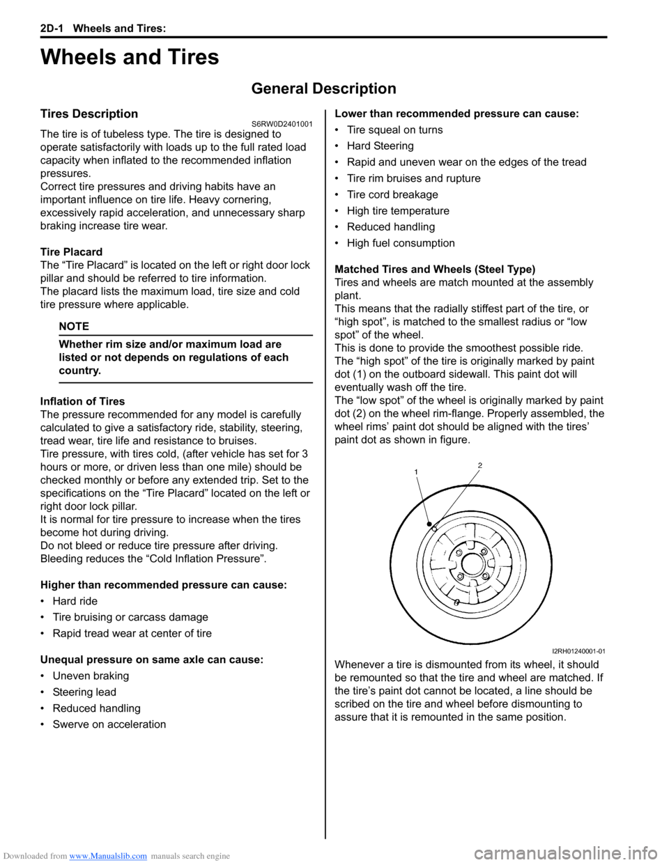
The “high spot” of the tire is originally marked by paint
dot (1) on the outboard sidewall. This paint dot will
eventually wash off the tire.
The “low spot” of the wheel is originally marked by paint
dot (2) on the wheel rim-flange. Properly assembled, the
wheel rims’ paint dot should be aligned with the tires’
paint dot as shown in figure.
Whenever a tire is dismounted from its wheel, it should
be remounted so that the tire and wheel are matched. If
the tire’s paint dot cannot be located, a line should be
scribed on the tire and wheel before dismounting to
assure that it is remounted in the same position.
I2RH01240001-01
Page 472 of 1556
Downloaded from www.Manualslib.com manuals search engine 2D-3 Wheels and Tires:
Irregular and/or Premature Wear DescriptionS6RW0D2401003
Irregular and premature wear has many causes. Some
of them are as follows: incorrect inflation pressures, lack
of tire rotation, driving habits, improper alignment.
If the following conditions are noted, tire rotation is
necessary:
• Front tire wear is different from rear’s.
• Uneven wear exists across tread of any tires.
• Both sides of front tire wears are not even.
• Both sides of rear tire wears are not even.
• There is cupping, flat spotting, etc.
A wheel alignment check is necessary if following
conditions are noted:
• Both sides of front tire wears are not even.
• Wear is uneven across the tread of any front tire.
• Front tire treads have scuffed appearance with
“feather” edges on one side of tread ribs or blocks.
Wear Indicators DescriptionS6RW0D2401004
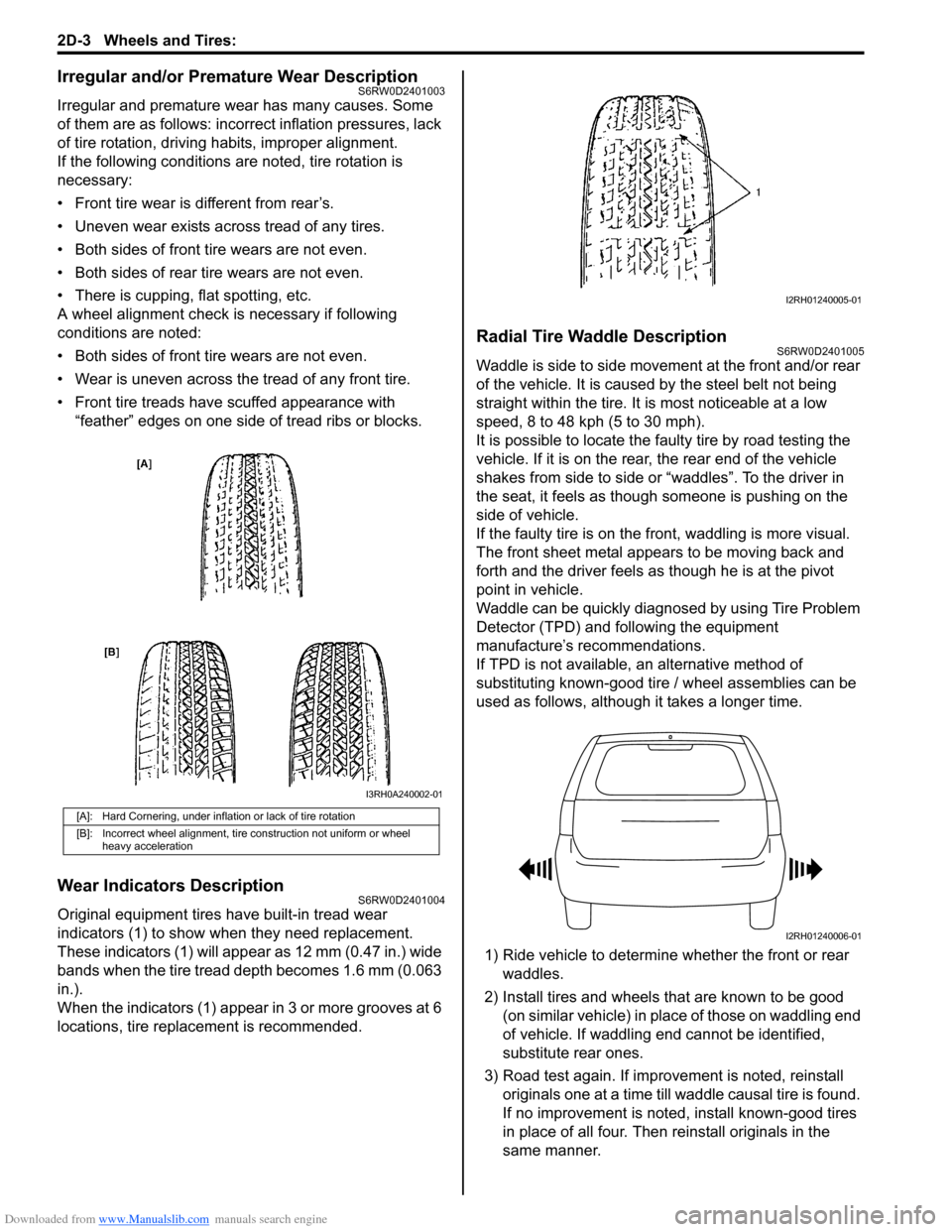
Original equipment tires have built-in tread wear
indicators (1) to show when they need replacement.
These indicators (1) will appear as 12 mm (0.47 in.) wide
bands when the tire tread depth becomes 1.6 mm (0.063
in.).
When the indicators (1) appear in 3 or more grooves at 6
locations, tire replacement is recommended.
Radial Tire Waddle DescriptionS6RW0D2401005
Waddle is side to side movement at the front and/or rear
of the vehicle. It is caused by the steel belt not being
straight within the tire. It is most noticeable at a low
speed, 8 to 48 kph (5 to 30 mph).
It is possible to locate the faulty tire by road testing the
vehicle. If it is on the rear, the rear end of the vehicle
shakes from side to side or “waddles”. To the driver in
the seat, it feels as though someone is pushing on the
side of vehicle.
If the faulty tire is on the front, waddling is more visual.
The front sheet metal appears to be moving back and
forth and the driver feels as though he is at the pivot
point in vehicle.
Waddle can be quickly diagnosed by using Tire Problem
Detector (TPD) and following the equipment
manufacture’s recommendations.
If TPD is not available, an alternative method of
substituting known-good tire / wheel assemblies can be
used as follows, although it takes a longer time.
1) Ride vehicle to determine whether the front or rear
waddles.
2) Install tires and wheels that are known to be good
(on similar vehicle) in place of those on waddling end
of vehicle. If waddling end cannot be identified,
substitute rear ones.
3) Road test again. If improvement is noted, reinstall
originals one at a time till waddle causal tire is found.
If no improvement is noted, install known-good tires
in place of all four. Then reinstall originals in the
same manner.
[A]: Hard Cornering, under inflation or lack of tire rotation
[B]: Incorrect wheel alignment, tire construction not uniform or wheel
heavy acceleration
I3RH0A240002-01
I2RH01240005-01
I2RH01240006-01
Page 504 of 1556
Downloaded from www.Manualslib.com manuals search engine 3B-7 Differential:
CAN Communication System DescriptionS6RW0D3201010
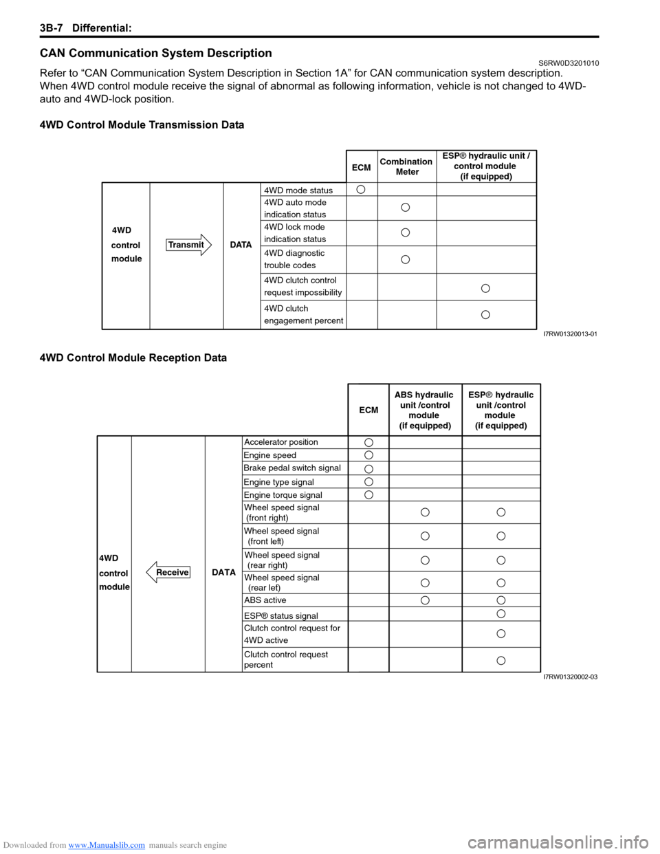
Refer to “CAN Communication System Description in Section 1A” for CAN communication system description.
When 4WD control module receive the signal of abnormal as following information, vehicle is not changed to 4WD-
auto and 4WD-lock position.
4WD Control Module Transmission Data
4WD Control Module Reception Data
ECMCombination
Meter
TransmitDATA 4WD
4WD mode status
4WD auto mode
indication status
4WD lock mode
indication status
4WD diagnostic
trouble codes control
module
4WD clutch
engagement percent
ESP® hydraulic unit /
control module
(if equipped)
4WD clutch control
request impossibility
I7RW01320013-01
Accelerator position
Engine speedECM
DATA
Brake pedal switch signal
4WD
control
moduleWheel speed signal
(front right)
Wheel speed signal
(front left)
Wheel speed signal
(rear right)
Wheel speed signal
(rear left)
ABS hydraulic
unit /control
module
(if equipped)
ESP® hydraulic
unit /control
module
(if equipped)
ABS active
ESP® status signal
Clutch control request for
4WD active
Clutch control request
percent
Engine type signal
Engine torque signal
Receive
I7RW01320002-03
Page 506 of 1556
Downloaded from www.Manualslib.com manuals search engine 3B-9 Differential:
Detail of 4WD Control System Check
Step 1. Customer complaint analysis
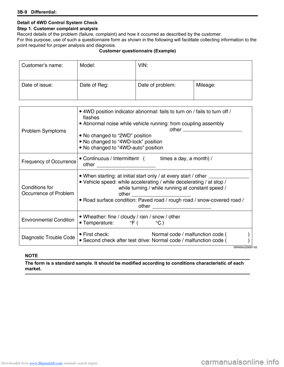
Record details of the problem (failure, complaint) and how it occurred as described by the customer.
For this purpose, use of such a questionnaire form as shown in the following will facilitate collecting information to the
point required for proper analysis and diagnosis.
Customer questionnaire (Example)
NOTE
The form is a standard sample. It should be modified according to conditions characteristic of each
market.
Customer’s name: Model: VIN:
Problem Symptoms
Frequency of Occurrence
Conditions for
Occurrence of Problem
Environmental Condition
Diagnostic Trouble Code
Date of Reg:
4WD position indicator abnormal: fails to turn on / fails to turn off /
flashes
Abnormal noise while vehicle running: from coupling assembly
other
No changed to “2WD” position
No changed to “4WD-lock” position
No changed to “4WD-auto” position
When starting: at initial start only / at every start / other
Vehicle speed: while accelerating / while decelerating / at stop /
while turning / while running at constant speed /
other
Road surface condition: Paved road / rough road / snow-covered road /
other
Wheather: fine / cloudy / rain / snow / other
Temperature: ( )
First check: Normal code / malfunction code ( )
Second check after test drive: Normal code / malfunction code ( ) Continuous / Intermittent ( times a day, a month) /
otherDate of problem: Mileage: Date of issue:
I5RW0A320007-02
Page 510 of 1556

Downloaded from www.Manualslib.com manuals search engine 3B-13 Differential:
Scan Tool DataS6RW0D3204009
Scan Tool Data Definitions
Accel pedal Pos (Accelerator pedal position) (%)
Accelerator pedal opening ratio detected by signal on
CAN communication line fed from ECM.
Engine Speed (RPM)
This parameter indicates engine revolution calculated by
4WD control module.
4WD mode (2WD / AUTO / LOCK / ABS mode / Yaw
cont / ESP® req)
This parameter indicates 4WD mode according to 2WD/
4WD switch signal status detected by 4WD control
module.
4WD current (A)
This parameter indicates input current of coupling
assembly.
Battery voltage (V)
This parameter indicates battery voltage detected by
4WD control module.Coupling temp (°C, °F)
Coupling temperature detected by coupling air
temperature sensor installed in coupling assembly.
Wheel speed (F), Wheel speed (R) (km/h, mph)
Wheel speed is an ABS / ESP® control module internal
parameter. It is computed by reference pulses from the
wheel speed sensor.
F-R Wheel speed diff (Front-rear wheel speed
differential) (rpm)
This parameter indicates rotation difference between
front wheel and rear wheel detected by 4WD control
module.
4WD duty (%)
This parameter indicates operation rate of coupling
assembly. Scan tool data Vehicle conditionNormal condition / reference
values
�) Accel pedal PosIgnition switch ON after
warmed up engineAccelerator pedal released 0 – 5%
Accelerator pedal depressed
fully90 – 100%
�) Engine speed At engine idle speed Engine idle speed is display
�) 4WD mode2WD/4WD switch selected to 2WD position 2WD
2WD/4WD switch selected to AUTO position AUTO
2WD/4WD switch selected to LOCK position LOCK
ABS operating ABS mode
Ignition switch ON and engine stop Relay off
Stability control operating Yaw cont
ESP® operating ESP® mode
�) 4WD current Engine running 0 – 200 mA
�) Battery voltage At engine idle speed 10 – 14 V
�) Coupling temp Engine running –40 °C – 100 °C (–40 °F – 212 °F)
�) Wheel speed (F) Vehicle stop 0 km/h, 0 MPH
�) Wheel speed (R) Vehicle stop 0 km/h, 0 MPH
�) F-R Wheel speed
DiffVehicle stop 0 rpm
�) 4WD dutyIgnition switch ON and 2WD/4WD switch selected to
2WD position0%
Page 511 of 1556
Downloaded from www.Manualslib.com manuals search engine Differential: 3B-14
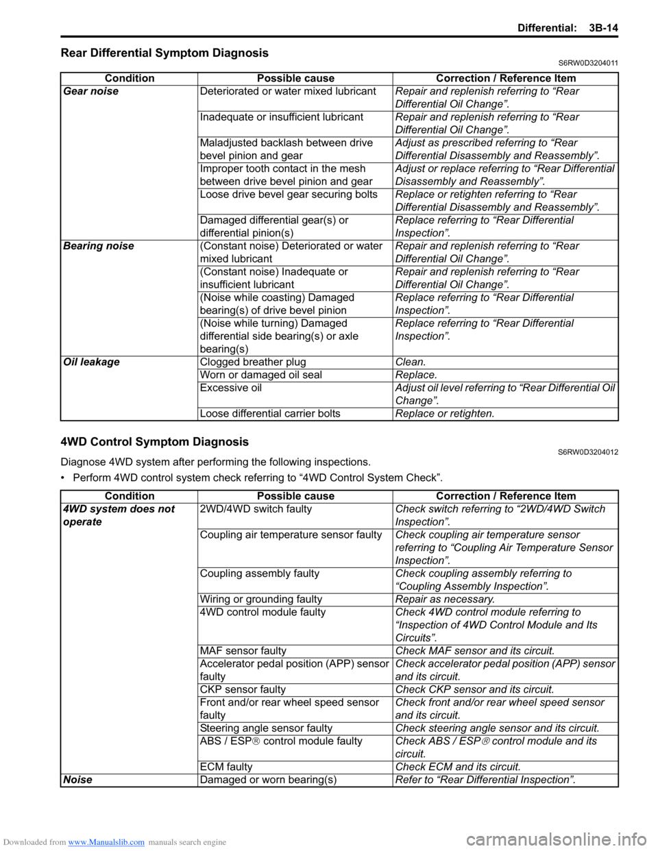
Rear Differential Symptom DiagnosisS6RW0D3204011
4WD Control Symptom DiagnosisS6RW0D3204012
Diagnose 4WD system after performing the following inspections.
• Perform 4WD control system check referring to “4WD Control System Check”. Condition Possible cause Correction / Reference Item
Gear noiseDeteriorated or water mixed lubricantRepair and replenish referring to “Rear
Differential Oil Change”.
Inadequate or insufficient lubricantRepair and replenish referring to “Rear
Differential Oil Change”.
Maladjusted backlash between drive
bevel pinion and gearAdjust as prescribed referring to “Rear
Differential Disassembly and Reassembly”.
Improper tooth contact in the mesh
between drive bevel pinion and gearAdjust or replace referring to “Rear Differential
Disassembly and Reassembly”.
Loose drive bevel gear securing boltsReplace or retighten referring to “Rear
Differential Disassembly and Reassembly”.
Damaged differential gear(s) or
differential pinion(s)Replace referring to “Rear Differential
Inspection”.
Bearing noise(Constant noise) Deteriorated or water
mixed lubricantRepair and replenish referring to “Rear
Differential Oil Change”.
(Constant noise) Inadequate or
insufficient lubricantRepair and replenish referring to “Rear
Differential Oil Change”.
(Noise while coasting) Damaged
bearing(s) of drive bevel pinionReplace referring to “Rear Differential
Inspection”.
(Noise while turning) Damaged
differential side bearing(s) or axle
bearing(s)Replace referring to “Rear Differential
Inspection”.
Oil leakageClogged breather plugClean.
Worn or damaged oil sealReplace.
Excessive oilAdjust oil level referring to “Rear Differential Oil
Change”.
Loose differential carrier boltsReplace or retighten.
Condition Possible cause Correction / Reference Item
4WD system does not
operate2WD/4WD switch faultyCheck switch referring to “2WD/4WD Switch
Inspection”.
Coupling air temperature sensor faultyCheck coupling air temperature sensor
referring to “Coupling Air Temperature Sensor
Inspection”.
Coupling assembly faultyCheck coupling assembly referring to
“Coupling Assembly Inspection”.
Wiring or grounding faultyRepair as necessary.
4WD control module faultyCheck 4WD control module referring to
“Inspection of 4WD Control Module and Its
Circuits”.
MAF sensor faultyCheck MAF sensor and its circuit.
Accelerator pedal position (APP) sensor
faultyCheck accelerator pedal position (APP) sensor
and its circuit.
CKP sensor faultyCheck CKP sensor and its circuit.
Front and/or rear wheel speed sensor
faultyCheck front and/or rear wheel speed sensor
and its circuit.
Steering angle sensor faultyCheck steering angle sensor and its circuit.
ABS / ESP® control module faultyCheck ABS / ESP
® control module and its
circuit.
ECM faultyCheck ECM and its circuit.
NoiseDamaged or worn bearing(s)Refer to “Rear Differential Inspection”.
Page 525 of 1556
Downloaded from www.Manualslib.com manuals search engine Differential: 3B-28
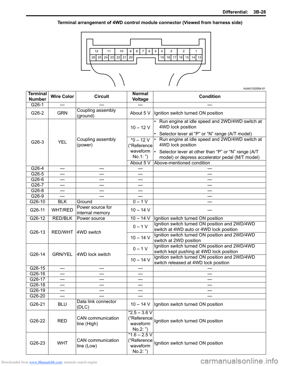
Terminal arrangement of 4WD control module connector (Viewed from harness side)
1 2 3 4 5 6 7 8 9 10 11 12
13 14 15 16 17 18 19 20 21 22 23 24 25 26
I4JA01332054-01
Terminal
NumberWire Color CircuitNormal
Vo l ta g eCondition
G26-1 — — — —
G26-2 GRNCoupling assembly
(ground)About 5 V Ignition switch turned ON position
G26-3 YELCoupling assembly
(power)10 – 12 V• Run engine at idle speed and 2WD/4WD switch at
4WD lock position
• Selector lever at “P” or “N” range (A/T model)
*0 – 12 V
(“Reference
waveform
No.1: ”)• Run engine at idle speed and 2WD/4WD switch at
4WD lock position
• Selector lever at other than “P” or “N” range (A/T
model) or depress accelerator pedal (M/T model)
About 5 V Above-mentioned condition
G26-4 — — — —
G26-5 — — — —
G26-6 — — — —
G26-7 — — — —
G26-8 — — — —
G26-9 — — — —
G26-10 BLK Ground 0 – 1 V —
G26-11 WHT/REDPower source for
internal memory10 – 14 V —
G26-12 RED/BLK Power source 10 – 14 V Ignition switch turned ON position
G26-13 RED/WHT 4WD switch0 – 1 VIgnition switch turned ON position and 2WD/4WD
switch at 4WD auto or 4WD lock position
10 – 14 VIgnition switch turned ON position and 2WD/4WD
switch at 2WD position
G26-14 GRN/YEL 4WD lock switch0 – 1 VIgnition switch turned ON position and 2WD/4WD
switch kept pushing at 4WD lock position
10 – 14 VIgnition switch turned ON position and 2WD/4WD
switch released at 4WD lock position
G26-15 — — — —
G26-16 — — — —
G26-17 — — — —
G26-18 — — — —
G26-19 — — — —
G26-20 — — — —
G26-21 BLUData link connector
(DLC)10 – 14 V Ignition switch turned ON position
G26-22 REDCAN communication
line (High)*2.5 – 3.6 V
(“Reference
waveform
No.2: ”)Ignition switch turned ON position
G26-23 WHTCAN communication
line (Low)*1.6 – 2.5 V
(“Reference
waveform
No.2: ”)Ignition switch turned ON position
Page 526 of 1556
Downloaded from www.Manualslib.com manuals search engine 3B-29 Differential:
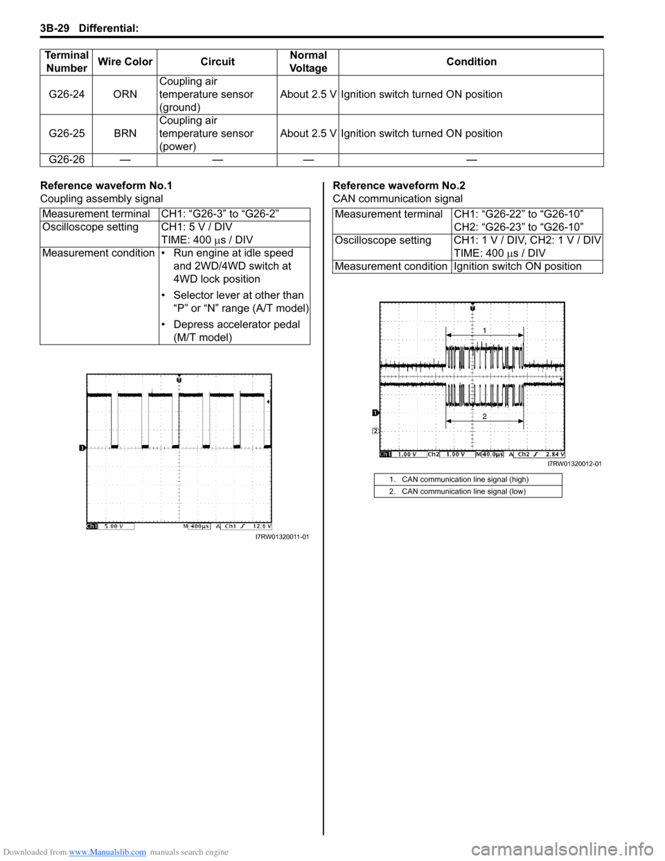
Reference waveform No.1
Coupling assembly signalReference waveform No.2
CAN communication signal G26-24 ORNCoupling air
temperature sensor
(ground)About 2.5 V Ignition switch turned ON position
G26-25 BRNCoupling air
temperature sensor
(power)About 2.5 V Ignition switch turned ON position
G26-26 — — — — Terminal
NumberWire Color CircuitNormal
Vo l ta g eCondition
Measurement terminal CH1: “G26-3” to “G26-2”
Oscilloscope setting CH1: 5 V / DIV
TIME: 400 µs / DIV
Measurement condition • Run engine at idle speed
and 2WD/4WD switch at
4WD lock position
• Selector lever at other than
“P” or “N” range (A/T model)
• Depress accelerator pedal
(M/T model)
I7RW01320011-01
Measurement terminal CH1: “G26-22” to “G26-10”
CH2: “G26-23” to “G26-10”
Oscilloscope setting CH1: 1 V / DIV, CH2: 1 V / DIV
TIME: 400 µs / DIV
Measurement condition Ignition switch ON position
1. CAN communication line signal (high)
2. CAN communication line signal (low)
I7RW01320012-01
Page 617 of 1556
Downloaded from www.Manualslib.com manuals search engine ABS: 4E-12
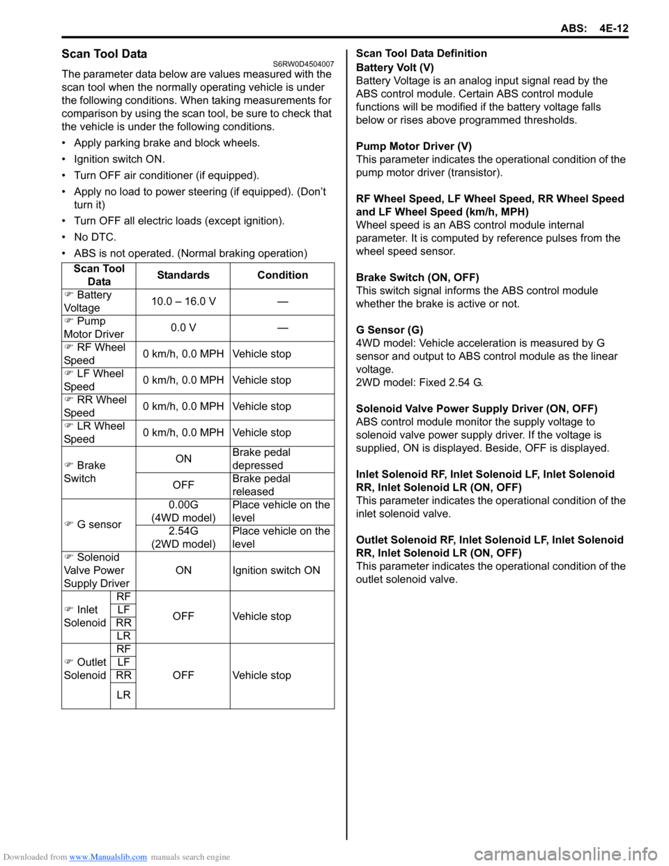
Scan Tool DataS6RW0D4504007
The parameter data below are values measured with the
scan tool when the normally operating vehicle is under
the following conditions. When taking measurements for
comparison by using the scan tool, be sure to check that
the vehicle is under the following conditions.
• Apply parking brake and block wheels.
• Ignition switch ON.
• Turn OFF air conditioner (if equipped).
• Apply no load to power steering (if equipped). (Don’t
turn it)
• Turn OFF all electric loads (except ignition).
• No DTC.
• ABS is not operated. (Normal braking operation)Scan Tool Data Definition
Battery Volt (V)
Battery Voltage is an analog input signal read by the
ABS control module. Certain ABS control module
functions will be modified if the battery voltage falls
below or rises above programmed thresholds.
Pump Motor Driver (V)
This parameter indicates the operational condition of the
pump motor driver (transistor).
RF Wheel Speed, LF Wheel Speed, RR Wheel Speed
and LF Wheel Speed (km/h, MPH)
Wheel speed is an ABS control module internal
parameter. It is computed by reference pulses from the
wheel speed sensor.
Brake Switch (ON, OFF)
This switch signal informs the ABS control module
whether the brake is active or not.
G Sensor (G)
4WD model: Vehicle acceleration is measured by G
sensor and output to ABS control module as the linear
voltage.
2WD model: Fixed 2.54 G.
Solenoid Valve Power Supply Driver (ON, OFF)
ABS control module monitor the supply voltage to
solenoid valve power supply driver. If the voltage is
supplied, ON is displayed. Beside, OFF is displayed.
Inlet Solenoid RF, Inlet Solenoid LF, Inlet Solenoid
RR, Inlet Solenoid LR (ON, OFF)
This parameter indicates the operational condition of the
inlet solenoid valve.
Outlet Solenoid RF, Inlet Solenoid LF, Inlet Solenoid
RR, Inlet Solenoid LR (ON, OFF)
This parameter indicates the operational condition of the
outlet solenoid valve. Scan Tool
DataStandards Condition
�) Battery
Voltage10.0 – 16.0 V —
�) Pump
Motor Driver0.0 V —
�) RF Wheel
Speed0 km/h, 0.0 MPH Vehicle stop
�) LF Wheel
Speed0 km/h, 0.0 MPH Vehicle stop
�) RR Wheel
Speed0 km/h, 0.0 MPH Vehicle stop
�) LR Wheel
Speed0 km/h, 0.0 MPH Vehicle stop
�) Brake
SwitchONBrake pedal
depressed
OFFBrake pedal
released
�) G sensor0.00G
(4WD model)Place vehicle on the
level
2.54G
(2WD model)Place vehicle on the
level
�) Solenoid
Valve Power
Supply DriverON Ignition switch ON
�) Inlet
SolenoidRF
OFF Vehicle stop LF
RR
LR
�) Outlet
SolenoidRF
OFF Vehicle stop LF
RR
LR
Page 657 of 1556
Downloaded from www.Manualslib.com manuals search engine Automatic Transmission/Transaxle: 5A-9
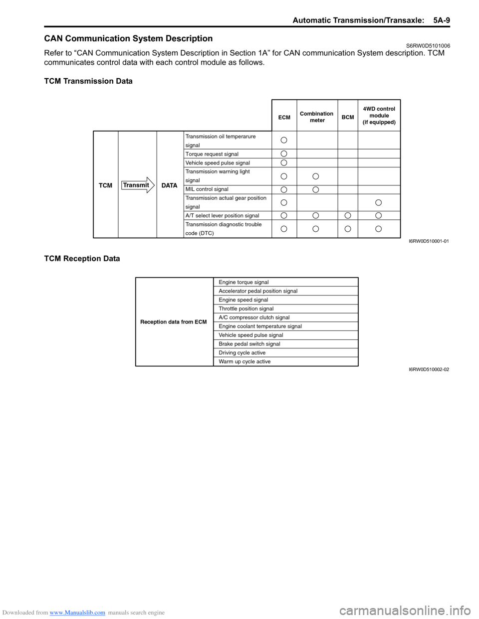
CAN Communication System DescriptionS6RW0D5101006
Refer to “CAN Communication System Description in Section 1A” for CAN communication System description. TCM
communicates control data with each control module as follows.
TCM Transmission Data
TCM Reception Data
DATA TCMTransmit
Transmission oil temperarure
signal
Torque request signal
Vehicle speed pulse signal
Transmission warning light
signal
MIL control signal
Transmission actual gear position
signal
A/T select lever position signal
Transmission diagnostic trouble
code (DTC)
ECMCombination
meterBCM
4WD control
module
(if equipped)
I6RW0D510001-01
Engine torque signal
Accelerator pedal position signal
Engine speed signal
Throttle position signal
A/C compressor clutch signal
Engine coolant temperature signal
Vehicle speed pulse signal
Brake pedal switch signal
Driving cycle active
Warm up cycle active Reception data from ECM
I6RW0D510002-02