151 SUZUKI SX4 2006 1.G Service Workshop Manual
[x] Cancel search | Manufacturer: SUZUKI, Model Year: 2006, Model line: SX4, Model: SUZUKI SX4 2006 1.GPages: 1556, PDF Size: 37.31 MB
Page 46 of 1556
Downloaded from www.Manualslib.com manuals search engine 1-ii Table of Contents
DTC P0123: Throttle Position Sensor (Main)
Circuit High ..................................................... 1A-89
DTC P0131 / P0132: O2 Sensor (HO2S)
Circuit Low Voltage / High Voltage (Sensor-
1) ..................................................................... 1A-92
DTC P0133: O2 Sensor (HO2S) Circuit Slow
Response (Sensor-1) ...................................... 1A-95
DTC P0134: O2 Sensor (HO2S) Circuit No
Activity Detected (Sensor-1) ........................... 1A-96
DTC P0137 / P0138: O2 Sensor (HO2S)
Circuit Low Voltage / High Voltage (Sensor-
2) ..................................................................... 1A-98
DTC P0140: O2 Sensor (HO2S) Circuit No
Activity Detected (Sensor-2) ......................... 1A-101
DTC P0171 / P0172: Fuel System Too Lean /
Rich ............................................................... 1A-103
DTC P0222: Throttle Position Sensor (Sub)
Circuit Low .................................................... 1A-105
DTC P0223: Throttle Position Sensor (Sub)
Circuit High ................................................... 1A-107
DTC P0300 / P0301 / P0302 / P0303 / P0304:
Random Misfire Detected / Cylinder 1 /
Cylinder 2 / Cylinder 3 / Cylinder 4 Misfire
Detected ........................................................ 1A-110
DTC P0327 / P0328: Knock Sensor Circuit
Low / High ..................................................... 1A-112
DTC P0335: Crankshaft Position (CKP)
Sensor Circuit ............................................... 1A-114
DTC P0340: Camshaft Position (CMP)
Sensor Circuit ............................................... 1A-116
DTC P0401 / P0402: Exhaust Gas
Recirculation Flow Insufficient Detected /
Excessive Detected ...................................... 1A-119
DTC P0403: Exhaust Gas Recirculation
Control Circuit ............................................... 1A-122
DTC P0420: Catalyst System Efficiency
below Threshold ............................................ 1A-124
DTC P0443: Evaporative Emission System
Purge Control Valve Circuit........................... 1A-126
DTC P0462 / P0463: Fuel Level Sensor
Circuit Low / High .......................................... 1A-128
DTC P0480: Fan 1 (Radiator Cooling Fan)
Control Circuit ............................................... 1A-129
DTC P0481: Cooling Fan 2 (A/C Condenser
Fan) Control Circuit ....................................... 1A-131
DTC P0500: Vehicle Speed Sensor (VSS)
Malfunction .................................................... 1A-134
DTC P0532: A/C Refrigerant Pressure
Sensor Circuit Low ........................................ 1A-136
DTC P0533: A/C Refrigerant Pressure
Sensor Circuit High ....................................... 1A-138
DTC P0601 / P0602 / P0607: Internal Control
Module Memory Check Sum Error / Control
Module Programming Error / Control Module
Performance ................................................. 1A-139
DTC P0616: Starter Relay Circuit Low............ 1A-140
DTC P0617: Starter Relay Circuit High ........... 1A-141
DTC P1510: ECM Back-Up Power Supply
Malfunction .................................................... 1A-143DTC P2101: Throttle Actuator Control Motor
Circuit Range / Performance ......................... 1A-144
DTC P2102: Throttle Actuator Control Motor
Circuit Low .................................................... 1A-146
DTC P2103: Throttle Actuator Control Motor
Circuit High.................................................... 1A-147
DTC P2111: Throttle Actuator Control System
- Stuck Open ................................................. 1A-148
DTC P2119: Throttle Actuator Control Throttle
Body Range / Performance ........................... 1A-149
DTC P2122: Pedal Position Sensor (Main)
Circuit Low Input ........................................... 1A-151
DTC P2123: Pedal Position Sensor (Main)
Circuit High Input........................................... 1A-153
DTC P2127: Pedal Position Sensor (Sub)
Circuit Low Input ........................................... 1A-155
DTC P2128: Pedal Position Sensor (Sub)
Circuit High Input........................................... 1A-158
DTC P2135: Throttle Position Sensor (Main /
Sub) Voltage Correlation ............................... 1A-160
DTC P2138: Pedal Position Sensor (Main /
Sub) Voltage Correlation ............................... 1A-163
DTC P2227 / P2228 / P2229: Barometric
Pressure Circuit Malfunction ......................... 1A-165
DTC U0073: Control Module Communication
Bus Off .......................................................... 1A-166
DTC U0101: Lost Communication with TCM .. 1A-166
DTC U0121: Lost Communication with ABS
Control Module .............................................. 1A-166
DTC U0140: Lost Communication with Body
Control Module .............................................. 1A-166
Troubleshooting for CAN-DTC ........................ 1A-167
Inspection of ECM and Its Circuits .................. 1A-172
ECM Power and Ground Circuit Check........... 1A-193
Fuel Injector Circuit Check .............................. 1A-196
Fuel Pump and Its Circuit Check..................... 1A-198
Fuel Pressure Check....................................... 1A-201
A/C Condenser Cooling Fan Control System
Inspection ...................................................... 1A-202
A/C System Circuits Check ............................. 1A-205
Electric Load Signal Circuit Check .................. 1A-209
Radiator Cooling Fan Control System Check . 1A-211
Repair Instructions ..........................................1A-212
Idle Speed and IAC Throttle Valve Opening
Inspection ...................................................... 1A-212
Special Tools and Equipment .........................1A-213
Special Tool .................................................... 1A-213
Aux. Emission Control Devices ............. 1B-1
Diagnostic Information and Procedures ............1B-1
EGR System Inspection (If Equipped) ................ 1B-1
Repair Instructions ..............................................1B-1
EVAP Canister Purge Inspection ........................ 1B-1
EVAP Canister Purge Valve and Its Circuit
Inspection .......................................................... 1B-1
Vacuum Passage Inspection............................... 1B-2
Vacuum Hose Inspection .................................... 1B-3
EVAP Canister Purge Valve Inspection .............. 1B-3
EVAP Canister Inspection ................................... 1B-4
Page 62 of 1556
Downloaded from www.Manualslib.com manuals search engine 1A-12 Engine General Information and Diagnosis:
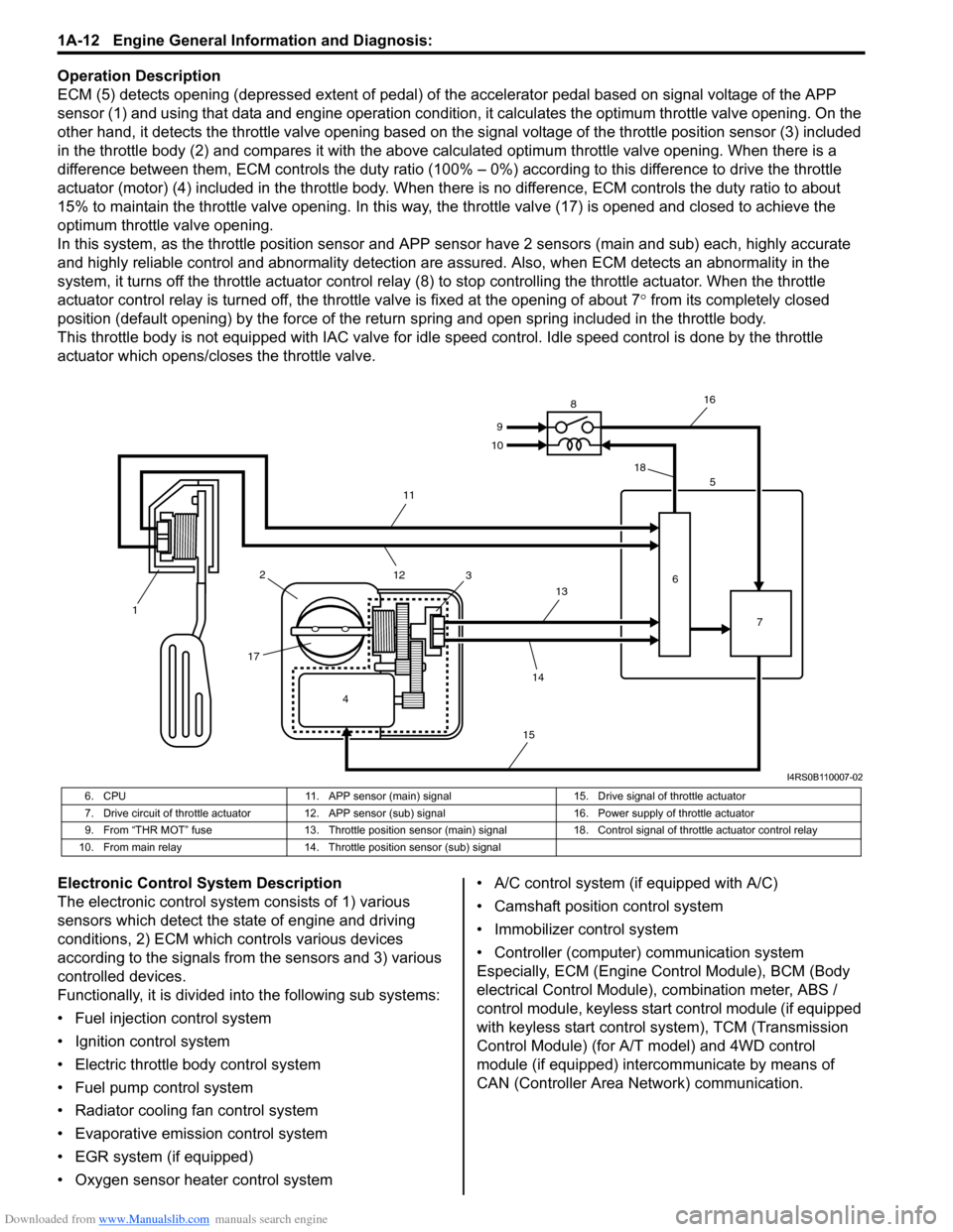
Operation Description
ECM (5) detects opening (depressed extent of pedal) of the accelerator pedal based on signal voltage of the APP
sensor (1) and using that data and engine operation condition, it calculates the optimum throttle valve opening. On the
other hand, it detects the throttle valve opening based on the signal voltage of the throttle position sensor (3) included
in the throttle body (2) and compares it with the above calculated optimum throttle valve opening. When there is a
difference between them, ECM controls the duty ratio (100% – 0%) according to this difference to drive the throttle
actuator (motor) (4) included in the throttle body. When there is no difference, ECM controls the duty ratio to about
15% to maintain the throttle valve opening. In this way, the throttle valve (17) is opened and closed to achieve the
optimum throttle valve opening.
In this system, as the throttle position sensor and APP sensor have 2 sensors (main and sub) each, highly accurate
and highly reliable control and abnormality detection are assured. Also, when ECM detects an abnormality in the
system, it turns off the throttle actuator control relay (8) to stop controlling the throttle actuator. When the throttle
actuator control relay is turned off, the throttle valve is fixed at the opening of about 7° from its completely closed
position (default opening) by the force of the return spring and open spring included in the throttle body.
This throttle body is not equipped with IAC valve for idle speed control. Idle speed control is done by the throttle
actuator which opens/closes the throttle valve.
Electronic Control System Description
The electronic control system consists of 1) various
sensors which detect the state of engine and driving
conditions, 2) ECM which controls various devices
according to the signals from the sensors and 3) various
controlled devices.
Functionally, it is divided into the following sub systems:
• Fuel injection control system
• Ignition control system
• Electric throttle body control system
• Fuel pump control system
• Radiator cooling fan control system
• Evaporative emission control system
• EGR system (if equipped)
• Oxygen sensor heater control system• A/C control system (if equipped with A/C)
• Camshaft position control system
• Immobilizer control system
• Controller (computer) communication system
Especially, ECM (Engine Control Module), BCM (Body
electrical Control Module), combination meter, ABS /
control module, keyless start control module (if equipped
with keyless start control system), TCM (Transmission
Control Module) (for A/T model) and 4WD control
module (if equipped) intercommunicate by means of
CAN (Controller Area Network) communication.
4 12
1735
6
7 8
9
10
11
12
13
14
1516
18
I4RS0B110007-02
6. CPU 11. APP sensor (main) signal 15. Drive signal of throttle actuator
7. Drive circuit of throttle actuator 12. APP sensor (sub) signal 16. Power supply of throttle actuator
9. From “THR MOT” fuse 13. Throttle position sensor (main) signal 18. Control signal of throttle actuator control relay
10. From main relay 14. Throttle position sensor (sub) signal
Page 77 of 1556
Downloaded from www.Manualslib.com manuals search engine Engine General Information and Diagnosis: 1A-27
Wiring Diagram
61
2
3
REDWHT
REDWHT
REDWHT
REDWHT
E01-3E01-18
E08-1E08-12
E08-2E08-13
G05-1G05-3
RED
WHT
REDWHTG16-19G16-18
5
REDWHTG05-2G05-4
8
9
REDWHT G26-23G26-22
4
REDWHTG241-9
G241-7
G241-10
G241-67
REDWHT
REDWHT
C06-17C06-7
C01-12C01-13 [B]
61
2
3
REDWHT
REDWHT
REDWHT
REDWHT
REDWHT
E01-3E01-18
E08-1E08-12
E08-2E08-13
E04-1E04-2
G04-4G04-2
REDWHT
REDWHTG16-19G16-18
5
REDWHTG04-3G04-1
8
9
REDWHT G26-23G26-22
4
REDWHTG241-9
G241-7G241-10
G241-67
REDWHT
REDWHT
C06-17C06-7
C01-12C01-13 [A]
87 6543 219 10 11 12 13 14 15 16
[C]
[D]
21
3 4
18 19 5 6 7 10 11
17 20
47 46 49 50 51 21 22
5216 259
24 14
29
55 57 54 53
59
60
582
26 27 28 15
30
56
4832 31 34 35 36 37 40 42 39 38 44
45 43 41 331 12 13
238 3 4
18 19 5 6 7 10 11
17 20
47 46 49 50 5121 22
5216 259
24 14
29
55 57 54 53
59
605826
27
28 15
30
56
4832 31 34 35 36 37 40 42 39 38 44
45 43 41 3312 13
238 E01 C011 2 3 10 11 12
16 17 18 15 14 13 19 20 21 25 24 23 22 2654 6 7 8 9 [E]
G26
65
15 16 14 13 12 1143
24 23 212210 9 8 721
19 20 18 17 C06 [F]1 2 3 4 7 8 9 10 11 14 15 16
36 3435 24 23
21 22 28 27 2526 37 39 38 4018 17 13 12 19 20
[G]
G16
[K]
1
17G2413 2 4 5 6 7 8 9 10111213141516
19 18 20 2122 23 24 25 26 27 28 29 30 31 32 [J]E081 2 3 4 5 6 712 13 14 15 16 17 18 19 20 21 22
8 9 10 11 23 24 25 26
1 2 3 4 5 6 7
1 2 3 4 5 6 7 8 9 10 11
8 9 10 11
12 13 1412 13 14
15 16 17
18 19 20 21 22G04 E04 [H]1 [I]
G05
2 3 4 7 8 9 10 11 14 15 16
36 3435 24 23 2122 28 27 2526 37 39 38 4018 17 13 12 19 2065
33 32 31 30 29
I6RW0D110017-01
Page 84 of 1556
Downloaded from www.Manualslib.com manuals search engine 1A-34 Engine General Information and Diagnosis:
)
U*P0420Catalyst system efficiency below
thresholdOutput waveforms of HO2S-1 and HO2S-2 are similar.2 driving
cycles
)
U*P0443Evaporative emission system purge
control valve circuitMonitor signal of EVAP canister purge valve is different
from command signal. (circuit open or shorted to ground)2 driving
cycles
) P0462 Fuel level sensor circuit lowCircuit voltage of fuel level sensor is less than
specification.—
) P0463 Fuel level sensor circuit highCircuit voltage of fuel level sensor is more than
specification.—
)
U*P0480Fan 1 control circuitMonitor signal of radiator cooling fan relay is different from
command signal.1 driving
cycle
)
UP0481Fan 2 control circuitMonitor signal of A/C condenser cooling fan relay is
different from command signal.—
) *P0500 Vehicle speed sensor No VSS signal during fuel cut for specified time or longer.2 driving
cycles
) P0532A/C refrigerant pressure sensor
circuit lowOutput voltage of A/C refrigerant pressure sensor is less
than specification.—
) P0533A/C refrigerant pressure sensor
circuit highOutput voltage of A/C refrigerant pressure sensor is more
than specification.—
) *P0601Internal control module memory
check sum errorData write error or check sum error.1 driving
cycle
) P0602 Control module programming error Data programming error.1 driving
cycle
) *P0607 Control module performance Data programming error.1 driving
cycle
)
U*P0616Starter relay circuit lowStarter signal is low voltage even though engine is started
with vehicle at stop.2 driving
cycles
)
U*P0617Starter relay circuit highStarter signal is high voltage for specified time while
engine is running.2 driving
cycles
) *P1510
ECM backup power supply
malfunctionBackup power voltage is out of specification after starting
engine.1 driving
cycle
) *P2101Throttle actuator control motor
circuit range/performanceMonitor signal of throttle actuator output (duty output) is
inconsistent with throttle actuator control command.1 driving
cycle
) *P2102Throttle actuator control motor
circuit lowPower supply voltage of throttle actuator control circuit is
lower than specification even if throttle actuator control
relay turned on.1 driving
cycle
) *P2103Throttle actuator control motor
circuit highPower supply voltage of throttle actuator control circuit is
higher than specification even if throttle actuator control
relay turned off.1 driving
cycle
) *P2111Throttle actuator control system –
stuck openThrottle valve default opening is greater than 8° from
complementary closed position when diagnosing throttle
valve at ignition switch turned OFF.1 driving
cycle
) *P2119Throttle actuator control throttle
body range/performanceDifference between actual throttle valve opening angle
and opening angle calculated by ECM is more than
specification.1 driving
cycle
) *P2122Pedal position sensor (main) circuit
low inputOutput voltage of pedal position sensor (main) is lower
than specification.1 driving
cycle
) *P2123Pedal position sensor (main) circuit
high inputOutput voltage of pedal position sensor (main) is higher
than specification.1 driving
cycle
) *P2127Pedal position sensor (sub) circuit
low inputOutput voltage of pedal position sensor (sub) is lower
than specification.1 driving
cycle
) *P2128Pedal position sensor (sub) circuit
high inputOutput voltage of pedal position sensor (sub) is higher
than specification.1 driving
cycle
) *P2135Throttle position sensor (main / sub)
voltage correlationDifference between the opening angle based on throttle
position sensor (main) and the opening angle based on
throttle position sensor (sub) is more than specification.1 driving
cycle DTC No. Detecting itemDetecting condition
(DTC will set when detecting:)MIL
Page 193 of 1556
Downloaded from www.Manualslib.com manuals search engine Engine General Information and Diagnosis: 1A-143
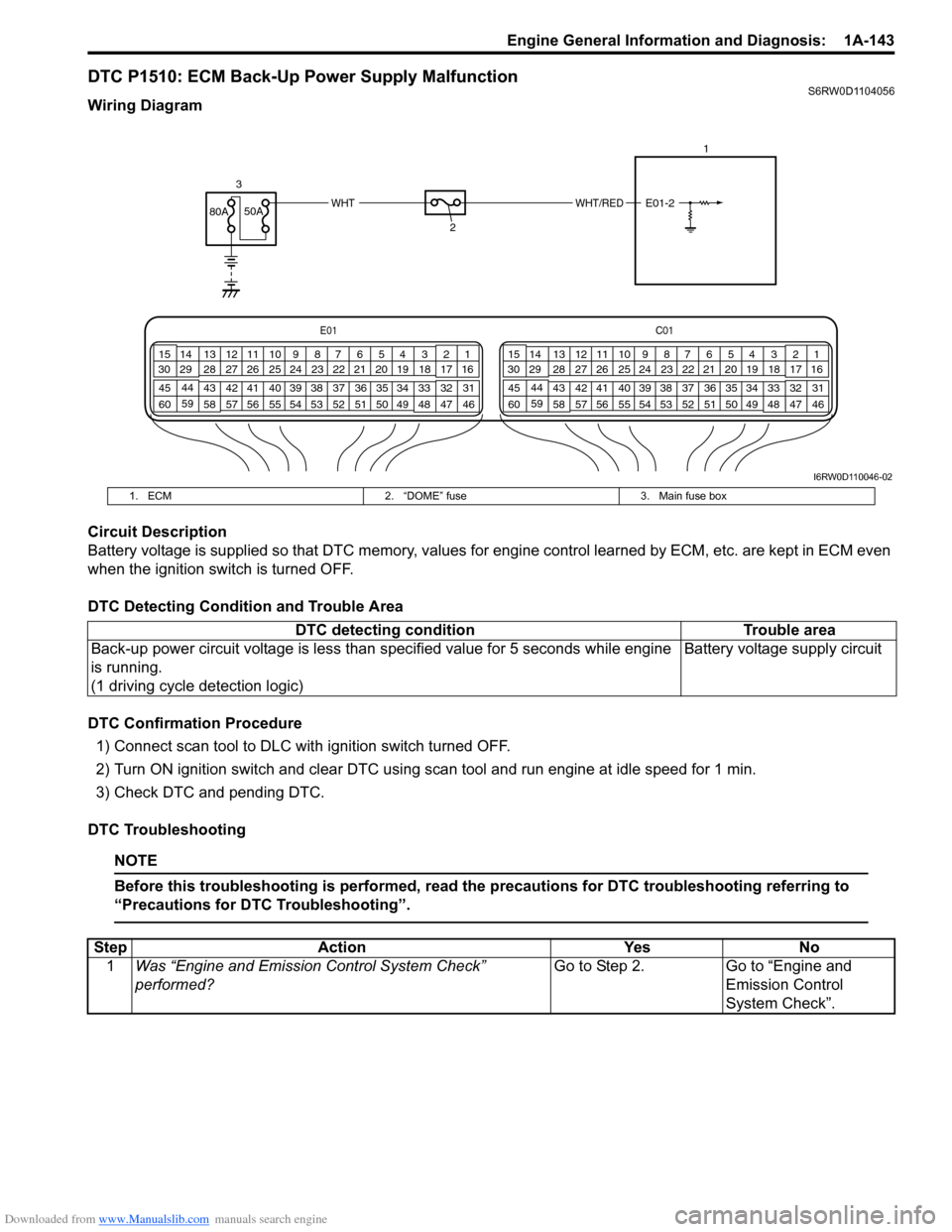
DTC P1510: ECM Back-Up Power Supply MalfunctionS6RW0D1104056
Wiring Diagram
Circuit Description
Battery voltage is supplied so that DTC memory, values for engine control learned by ECM, etc. are kept in ECM even
when the ignition switch is turned OFF.
DTC Detecting Condition and Trouble Area
DTC Confirmation Procedure
1) Connect scan tool to DLC with ignition switch turned OFF.
2) Turn ON ignition switch and clear DTC using scan tool and run engine at idle speed for 1 min.
3) Check DTC and pending DTC.
DTC Troubleshooting
NOTE
Before this troubleshooting is performed, read the precautions for DTC troubleshooting referring to
“Precautions for DTC Troubleshooting”.
E01C01
3 4
18 19 5 6 7 10 11
17 20
47 46 49 50 51 21 22
5216 259
24 14
29
55 57 54 53 59
60 582
26 27 28 15
30
56 4832 31 34 35 36 37 40 42 39 38 44
45 43 41 331 12 13
238 3 4
18 19 5 6 7 10 11
17 20
47 46 49 50 51 21 22
5216 259
24 14
29
55 57 54 53 59
60 582
26 27 28 15
30
56 4832 31 34 35 36 37 40 42 39 38 44
45 43 41 331 12 13
238
WHT/REDWHT80A50A
3
21
E01-2
I6RW0D110046-02
1. ECM 2. “DOME” fuse 3. Main fuse box
DTC detecting condition Trouble area
Back-up power circuit voltage is less than specified value for 5 seconds while engine
is running.
(1 driving cycle detection logic)Battery voltage supply circuit
Step Action Yes No
1Was “Engine and Emission Control System Check”
performed?Go to Step 2. Go to “Engine and
Emission Control
System Check”.
Page 201 of 1556

Downloaded from www.Manualslib.com manuals search engine Engine General Information and Diagnosis: 1A-151
DTC P2122: Pedal Position Sensor (Main) Circuit Low InputS6RW0D1104062
Wiring Diagram
DTC Detecting Condition and Trouble Area
DTC Confirmation Procedure
1) With ignition switch turned OFF, connect scan tool.
2) Turn ON ignition switch and clear DTC using scan tool.
3) Keep the accelerator pedal at idle position for 2 seconds.
4) Keep the accelerator pedal at fully depressed position for 2 seconds.
5) Repeat Step 3) and 4) for 3 times.
6) Check DTC.
E01C01
3 4
18 19 5 6 7 10 11
17 20
47 46 49 50 51 21 22
5216 259
24 14
29
55 57 54 53 59
60 582
26 27 28 15
30
56 4832 31 34 35 36 37 40 42 39 38 44
45 43 41 331 12 13
238 3 4
18 19 5 6 7 10 11
17 20
47 46 49 50 51 21 22
5216 259
24 14
29
55 57 54 53 59
60 582
26 27 28 15
30
56 4832 31 34 35 36 37 40 42 39 38 44
45 43 41 331 12 13
238
BRN
GRN
BLU
RED
YEL
WHT
E01-35
E01-37
E01-52
E01-34
E01-36
E01-51
E01-505 V
5 V 1
1-132
1-2
BLK
I6RW0D110048-01
1. APP sensor assembly 1-2. APP sensor (sub) 3. Ground of APP sensor for shield wire
1-1. APP sensor (main) 2. ECM
DTC detecting condition Trouble area
Output voltage of APP sensor (main) is lower than specified value.
(1 driving detection logic)• APP sensor (main) circuit
• APP sensor assembly
•ECM
• Incorrect mounting of APP sensor assembly
Page 348 of 1556
Downloaded from www.Manualslib.com manuals search engine 1D-66 Engine Mechanical:
Selection of Main Bearings
Standard bearing
If bearing is in malcondition, or bearing clearance is out
of specification, select a new standard bearing according
to the following procedure and install it.
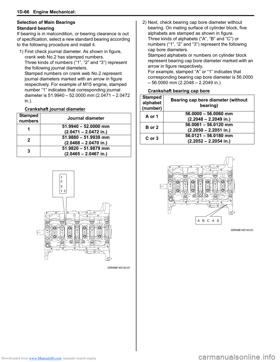
1) First check journal diameter. As shown in figure,
crank web No.2 has stamped numbers.
Three kinds of numbers (“1”, “2” and “3”) represent
the following journal diameters.
Stamped numbers on crank web No.2 represent
journal diameters marked with an arrow in figure
respectively. For example of M15 engine, stamped
number “1” indicates that corresponding journal
diameter is 51.9940 – 52.0000 mm (2.0471 – 2.0472
in.).
Crankshaft journal diameter2) Next, check bearing cap bore diameter without
bearing. On mating surface of cylinder block, five
alphabets are stamped as shown in figure.
Three kinds of alphabets (“A”, “B” and “C”) or
numbers (“1”, “2” and “3”) represent the following
cap bore diameters.
Stamped alphabets or numbers on cylinder block
represent bearing cap bore diameter marked with an
arrow in figure respectively.
For example, stamped “A” or “1” indicates that
corresponding bearing cap bore diameter is 56.0000
– 56.0060 mm (2.2048 – 2.2049 in.).
Crankshaft bearing cap bore
Stamped
numbersJournal diameter
151.9940 – 52.0000 mm
(2.0471 – 2.0472 in.)
251.9880 – 51.9939 mm
(2.0468 – 2.0470 in.)
351.9820 – 51.9879 mm
(2.0465 – 2.0467 in.)
I2RH0B140142-01
Stamped
alphabet
(number)Bearing cap bore diameter (without
bearing)
A or 156.0000 – 56.0060 mm
(2.2048 – 2.2049 in.)
B or 256.0061 – 56.0120 mm
(2.2050 – 2.2051 in.)
C or 356.0121 – 56.0180 mm
(2.2052 – 2.2054 in.)
I2RH0B140143-01
Page 352 of 1556
Downloaded from www.Manualslib.com manuals search engine 1D-70 Engine Mechanical:
Main Bearing Cap No.1 Bolt
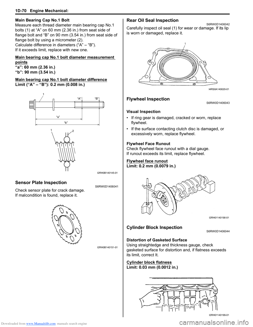
Measure each thread diameter main bearing cap No.1
bolts (1) at “A” on 60 mm (2.36 in.) from seat side of
flange bolt and “B” on 90 mm (3.54 in.) from seat side of
flange bolt by using a micrometer (2).
Calculate difference in diameters (“A” – “B”).
If it exceeds limit, replace with new one.
Main bearing cap No.1 bolt diameter measurement
points
“a”: 60 mm (2.36 in.)
“b”: 90 mm (3.54 in.)
Main bearing cap No.1 bolt diameter difference
Limit (“A” – “B”): 0.2 mm (0.008 in.)
Sensor Plate InspectionS6RW0D1406041
Check sensor plate for crack damage.
If malcondition is found, replace it.
Rear Oil Seal InspectionS6RW0D1406042
Carefully inspect oil seal (1) for wear or damage. If its lip
is worn or damaged, replace it.
Flywheel InspectionS6RW0D1406043
Visual Inspection
• If ring gear is damaged, cracked or worn, replace
flywheel.
• If the surface contacting clutch disc is damaged, or
excessively worn, replace flywheel.
Flywheel Face Runout
Check flywheel face runout with a dial gauge.
If runout exceeds its limit, replace flywheel.
Flywheel face runout
Limit: 0.2 mm (0.0079 in.)
Cylinder Block InspectionS6RW0D1406044
Distortion of Gasketed Surface
Using straightedge and thickness gauge, check
gasketed surface for distortion and, if flatness exceeds
its limit, correct It.
Cylinder block flatness
Limit: 0.03 mm (0.0012 in.)
“A”
“a”
“b”“B”
1
1
2
I2RH0B140145-01
I2RH0B140151-01
I4RS0A140020-01
I2RH01140198-01
I2RH01140199-01
Page 359 of 1556
Downloaded from www.Manualslib.com manuals search engine Engine Lubrication System: 1E-3
8) Start engine and check oil pressure switch for oil
leakage. If oil leakage is found, repair it.
9) Connect oil pressure switch coupler (1).
Repair Instructions
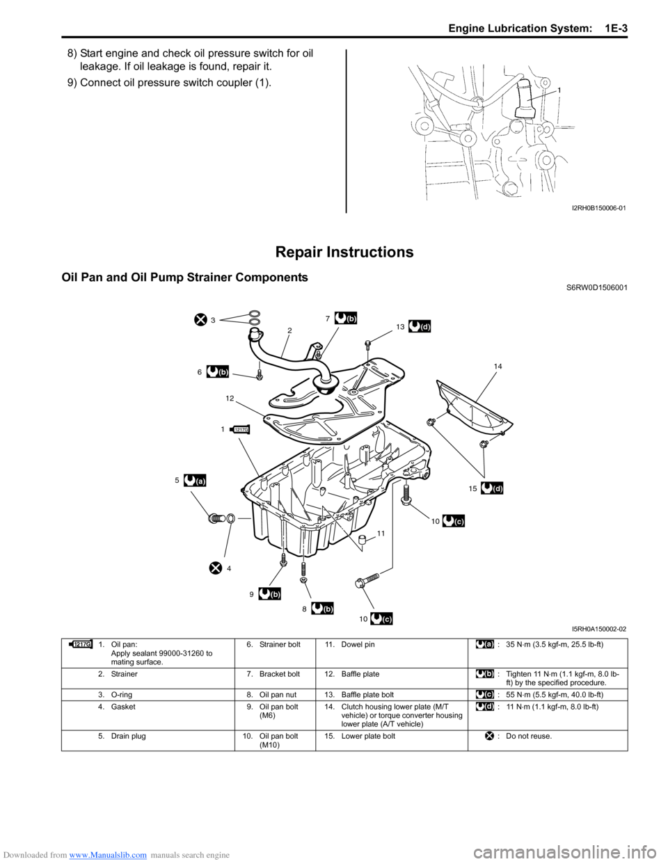
Oil Pan and Oil Pump Strainer ComponentsS6RW0D1506001
I2RH0B150006-01
1
23
4
(a) 5
(b) 6
(b) 8
(b) 9
(b) 7
10
(c)10
(c)
11 12
(d) 13
(d) 1514
I5RH0A150002-02
1. Oil pan:
Apply sealant 99000-31260 to
mating surface.6. Strainer bolt 11. Dowel pin : 35 N⋅m (3.5 kgf-m, 25.5 lb-ft)
2. Strainer 7. Bracket bolt 12. Baffle plate : Tighten 11 N⋅m (1.1 kgf-m, 8.0 lb-
ft) by the specified procedure.
3. O-ring 8. Oil pan nut 13. Baffle plate bolt : 55 N⋅m (5.5 kgf-m, 40.0 lb-ft)
4. Gasket 9. Oil pan bolt
(M6)14. Clutch housing lower plate (M/T
vehicle) or torque converter housing
lower plate (A/T vehicle):11 N⋅m (1.1 kgf-m, 8.0 lb-ft)
5. Drain plug 10. Oil pan bolt
(M10)15. Lower plate bolt : Do not reuse.
Page 429 of 1556
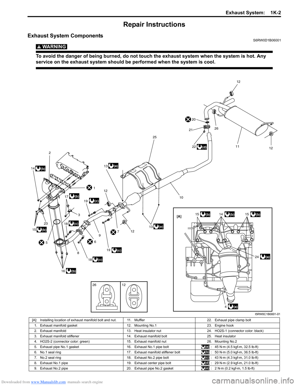
Downloaded from www.Manualslib.com manuals search engine Exhaust System: 1K-2
Repair Instructions
Exhaust System ComponentsS6RW0D1B06001
WARNING!
To avoid the danger of being burned, do not touch the exhaust system when the system is hot. Any
service on the exhaust system should be performed when the system is cool.
[A]
1
2
3
4
56
7
8
9
10
11
12
12
26
12
12
141515
16
26 12
17
18
18
19
19
20
21
23
22
24
25
(a)(c)
(c)
(d)
(e)
(b)
(a)
(b)(b)
(c)
(c)
(b)
(b)
14(b)
15(b)13
(e)
13
I5RW0C1B0001-01
[A]: Installing location of exhaust manifold bolt and nut. 11. Muffler 22. Exhaust pipe clamp bolt
1. Exhaust manifold gasket 12. Mounting No.1 23. Engine hook
2. Exhaust manifold 13. Heat insulator nut 24. HO2S-1 (connector color: black)
3. Exhaust manifold stiffener 14. Exhaust manifold bolt 25. Heat insulator
4. HO2S-2 (connector color: green) 15. Exhaust manifold nut 26. Mounting No.2
5. Exhaust pipe No.1 gasket 16. Exhaust No.1 pipe bolt : 45 N⋅m (4.5 kgf-m, 32.5 lb-ft)
6. No.1 seal ring 17. Exhaust manifold stiffener bolt : 50 N⋅m (5.0 kgf-m, 36.5 lb-ft)
7. No.2 seal ring 18. Exhaust No.2 pipe bolt : 43 N⋅m (4.3 kgf-m, 31.0 lb-ft)
8. Exhaust No.1 pipe 19. Exhaust center pipe bolt : 29 N⋅m (2.9 kgf-m, 21.0 lb-ft)
9. Exhaust No.2 pipe 20. Exhaust pipe No.2 gasket : 2 N⋅m (0.2 kgf-m, 1.5 lb-ft)