Remove console box SUZUKI SX4 2006 1.G Service Workshop Manual
[x] Cancel search | Manufacturer: SUZUKI, Model Year: 2006, Model line: SX4, Model: SUZUKI SX4 2006 1.GPages: 1556, PDF Size: 37.31 MB
Page 528 of 1556
Downloaded from www.Manualslib.com manuals search engine 3B-31 Differential:
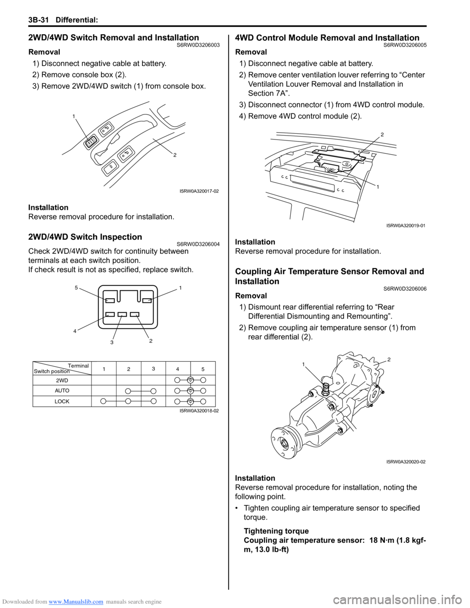
2WD/4WD Switch Removal and InstallationS6RW0D3206003
Removal
1) Disconnect negative cable at battery.
2) Remove console box (2).
3) Remove 2WD/4WD switch (1) from console box.
Installation
Reverse removal procedure for installation.
2WD/4WD Switch InspectionS6RW0D3206004
Check 2WD/4WD switch for continuity between
terminals at each switch position.
If check result is not as specified, replace switch.
4WD Control Module Removal and InstallationS6RW0D3206005
Removal
1) Disconnect negative cable at battery.
2) Remove center ventilation louver referring to “Center
Ventilation Louver Removal and Installation in
Section 7A”.
3) Disconnect connector (1) from 4WD control module.
4) Remove 4WD control module (2).
Installation
Reverse removal procedure for installation.
Coupling Air Temperature Sensor Removal and
Installation
S6RW0D3206006
Removal
1) Dismount rear differential referring to “Rear
Differential Dismounting and Remounting”.
2) Remove coupling air temperature sensor (1) from
rear differential (2).
Installation
Reverse removal procedure for installation, noting the
following point.
• Tighten coupling air temperature sensor to specified
torque.
Tightening torque
Coupling air temperature sensor: 18 N·m (1.8 kgf-
m, 13.0 lb-ft)
1
2
I5RW0A320017-02
Terminal
Switch position
2WD
AUTO
LOCK
11
22
3 3
4 4
5 5
I5RW0A320018-02
2
1
I5RW0A320019-01
12
I5RW0A320020-02
Page 604 of 1556
Downloaded from www.Manualslib.com manuals search engine 4D-3 Parking Brake:
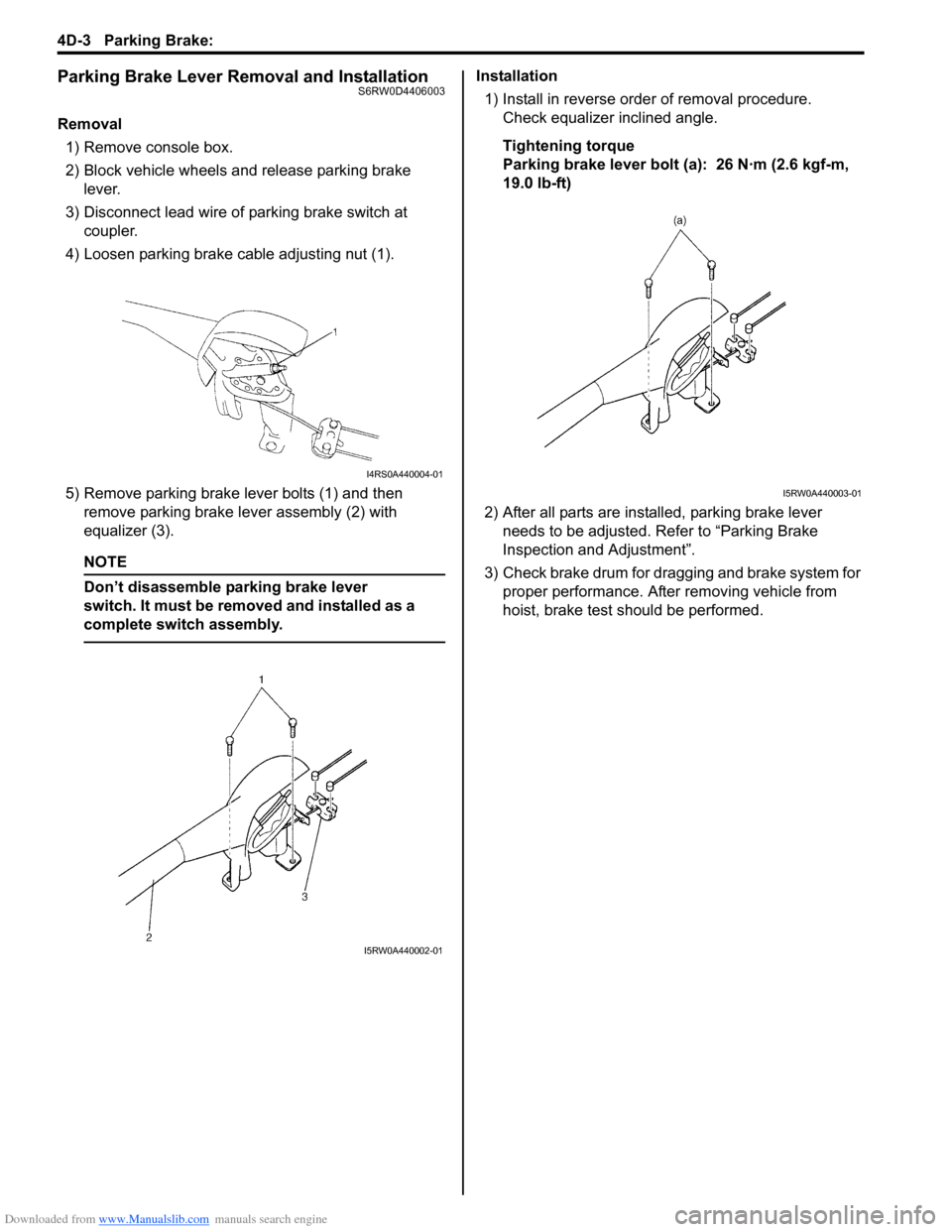
Parking Brake Lever Removal and InstallationS6RW0D4406003
Removal
1) Remove console box.
2) Block vehicle wheels and release parking brake
lever.
3) Disconnect lead wire of parking brake switch at
coupler.
4) Loosen parking brake cable adjusting nut (1).
5) Remove parking brake lever bolts (1) and then
remove parking brake lever assembly (2) with
equalizer (3).
NOTE
Don’t disassemble parking brake lever
switch. It must be removed and installed as a
complete switch assembly.
Installation
1) Install in reverse order of removal procedure.
Check equalizer inclined angle.
Tightening torque
Parking brake lever bolt (a): 26 N·m (2.6 kgf-m,
19.0 lb-ft)
2) After all parts are installed, parking brake lever
needs to be adjusted. Refer to “Parking Brake
Inspection and Adjustment”.
3) Check brake drum for dragging and brake system for
proper performance. After removing vehicle from
hoist, brake test should be performed.
I4RS0A440004-01
I5RW0A440002-01
I5RW0A440003-01
Page 643 of 1556
Downloaded from www.Manualslib.com manuals search engine ABS: 4E-38
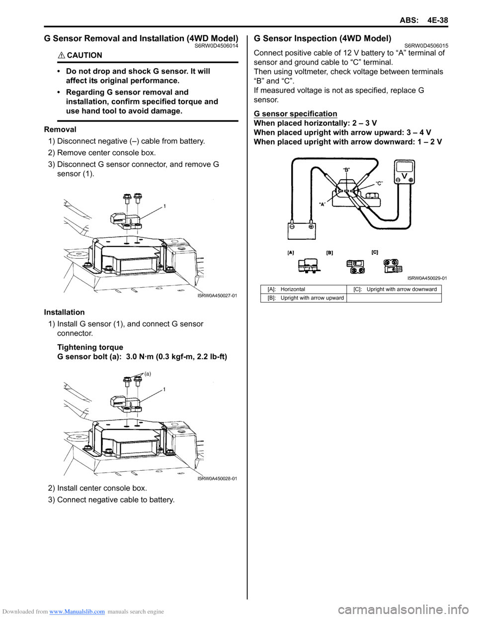
G Sensor Removal and Installation (4WD Model)S6RW0D4506014
CAUTION!
• Do not drop and shock G sensor. It will
affect its original performance.
• Regarding G sensor removal and
installation, confirm specified torque and
use hand tool to avoid damage.
Removal
1) Disconnect negative (–) cable from battery.
2) Remove center console box.
3) Disconnect G sensor connector, and remove G
sensor (1).
Installation
1) Install G sensor (1), and connect G sensor
connector.
Tightening torque
G sensor bolt (a): 3.0 N·m (0.3 kgf-m, 2.2 lb-ft)
2) Install center console box.
3) Connect negative cable to battery.
G Sensor Inspection (4WD Model)S6RW0D4506015
Connect positive cable of 12 V battery to “A” terminal of
sensor and ground cable to “C” terminal.
Then using voltmeter, check voltage between terminals
“B” and “C”.
If measured voltage is not as specified, replace G
sensor.
G sensor specification
When placed horizontally: 2 – 3 V
When placed upright with arrow upward: 3 – 4 V
When placed upright with arrow downward: 1 – 2 V
I5RW0A450027-01
I5RW0A450028-01
[A]: Horizontal [C]: Upright with arrow downward
[B]: Upright with arrow upward
I5RW0A450029-01
Page 733 of 1556
Downloaded from www.Manualslib.com manuals search engine Automatic Transmission/Transaxle: 5A-85
Select Lever InspectionS6RW0D5106005
Check select lever for smooth and clear-cut movement
individually. If a malfunction is found, replace select lever
assembly.
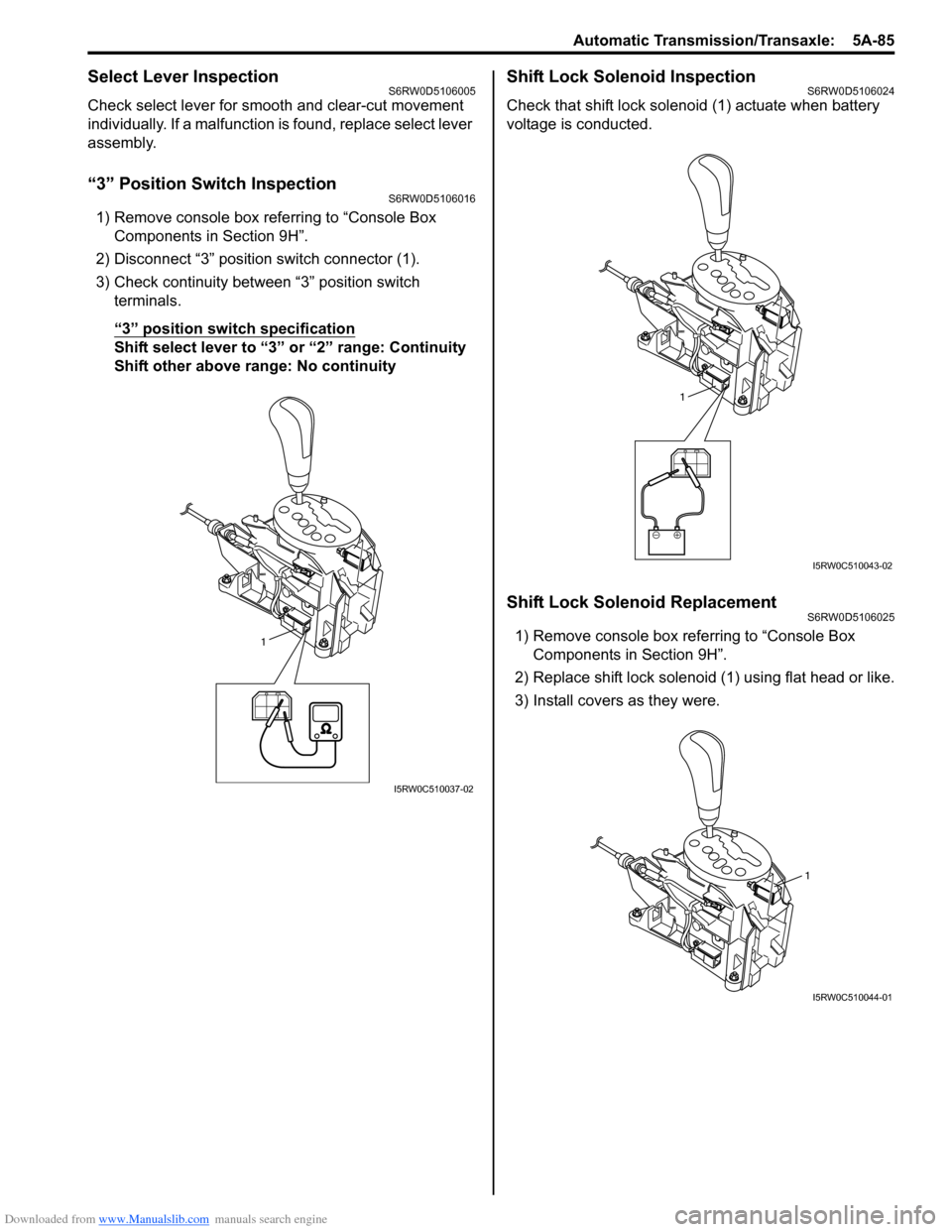
“3” Position Switch InspectionS6RW0D5106016
1) Remove console box referring to “Console Box
Components in Section 9H”.
2) Disconnect “3” position switch connector (1).
3) Check continuity between “3” position switch
terminals.
“3” position switch specification
Shift select lever to “3” or “2” range: Continuity
Shift other above range: No continuity
Shift Lock Solenoid InspectionS6RW0D5106024
Check that shift lock solenoid (1) actuate when battery
voltage is conducted.
Shift Lock Solenoid ReplacementS6RW0D5106025
1) Remove console box referring to “Console Box
Components in Section 9H”.
2) Replace shift lock solenoid (1) using flat head or like.
3) Install covers as they were.1
I5RW0C510037-02
1
I5RW0C510043-02
1
I5RW0C510044-01
Page 734 of 1556

Downloaded from www.Manualslib.com manuals search engine 5A-86 Automatic Transmission/Transaxle:
Select Cable ComponentsS6RW0D5106006
Select Cable Removal and InstallationS6RW0D5106007
Removal
1) Remove console box referring to “Console Box
Components in Section 9H”.
2) Disconnect select cable from select lever and then
detach from bracket.
3) Remove clip and disconnect select cable from
manual select lever.
4) Remove select cable retainer from dash panel.
Installation
Install select cable by reversing removal procedure.
The important steps in installation are as follows.
• Apply grease to pin and cable joint.
• Tighten bolts to specified torque referring to “Select
Cable Components”.• Adjusting procedure is as follows. Refer to “Select
Cable Adjustment”.Select Cable AdjustmentS6RW0D5106008
1) Shift manual shift lever to “N” range (transmission
range sensor “N” range).
(a)
(b)
(c)
6
7A
112
[B]
[B] [A]
[A]
34
5
9
8
101
A
I5RW0C510031-01
[A]: View [A] 5. Clip 11. Radiator inlet hose
[B]: View [B] 6. Manual select lever pin
: Apply lithium grease 99000-25011 to all around pin (0.15 g):23 N⋅m (2.0 kgf-m, 17.0 lb-ft)
1. Select lever assembly 7. Select lever pin
: Apply lithium grease 99000-25011 to all around pin (0.15 g):6.5 N⋅m (0.65 kgf-m, 5.0 lb-ft)
2. Select cable 8. Adjuster case : 13 N⋅m (1.3 kgf-m, 9.5 lb-ft)
3. Cable bracket 9. Lock
4. Manual select lever 10. P/S control module
“P”“R”“N”
“D”
“2”
“L”
I2RH0B510040-01
Page 735 of 1556

Downloaded from www.Manualslib.com manuals search engine Automatic Transmission/Transaxle: 5A-87
2) Remove adjuster (cable end) from select lever pin of
select lever assembly.
3) Remove adjuster (cable end) from select lever pin of
select lever assembly.
4) Release lock plate (1) which restrict moving of cable
end holder (2).
5) Push cable end holder (1) out from eye-end (2) using
an appropriate tool (3) to disengage cable.
6) Shift select lever to “N” position.
7) Apply grease to select lever pin and install adjuster
(cable end) to it.
: Grease 99000–25011 (SUZUKI Super Grease
A)
8) With both select lever and transmission range
sensor kept each “N” position, drive cable end holder
(1) in until it locks cable.
9) Slide lock plate (2) to secure cable end holder in
position.
10) After select cable was installed, check for the
following.
• Push vehicle with select lever shifted to “P” range.
Vehicle should not move.
• Vehicle can not be driven in “N” range.• Vehicle can be driven in “D”, “3”, “2” and “L”
ranges.
• Vehicle can be backed in “R” range.
Key Interlock Cable Removal and InstallationS6RW0D5106026
NOTE
Don’t bend interlock cable excessively when
removing and installing it, or system will not
operate correctly.
Removal
1) If the vehicle is equipped with air bag system,
disconnect negative cable at battery and disable air
bag system, referring to “Disabling Air Bag System in
Section 8B”.
2) Remove steering column cover.
3) Turn ignition switch to ACC position.
4) Pull out key interlock cable (1) from key cylinder
cover (2) while pressing checkhook with slotted
screwdriver (3) or the like.
5) Turn ignition switch to LOCK position.
6) Remove console box referring to “Console Box
Components in Section 9H”.
7) Detach cable end (1) from interlock cam (2) while
pressing claws (3) of interlock cam boss.
At this time, be careful not to cause damage to its
claws.
Detach cable casing cap (4) from bracket (5) while
pressing checkhook.
8) Remove interlock cable.
I2RH01510046-01
I2RH01510047-01
I3RM0B510037-01
2
13I5RW0C510045-01
4
5 3 12
4
I5RW0C510046-01
Page 821 of 1556
Downloaded from www.Manualslib.com manuals search engine Manual Transmission/Transaxle: 5B-9
Gear Shift Control Lever and Cable Removal
and Installation
S6RW0D5206005
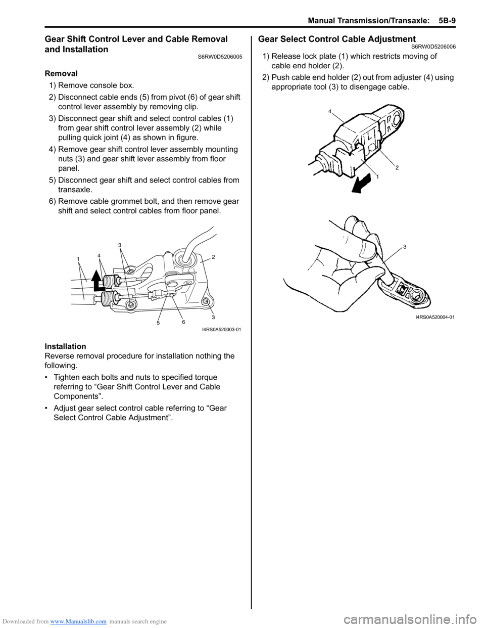
Removal
1) Remove console box.
2) Disconnect cable ends (5) from pivot (6) of gear shift
control lever assembly by removing clip.
3) Disconnect gear shift and select control cables (1)
from gear shift control lever assembly (2) while
pulling quick joint (4) as shown in figure.
4) Remove gear shift control lever assembly mounting
nuts (3) and gear shift lever assembly from floor
panel.
5) Disconnect gear shift and select control cables from
transaxle.
6) Remove cable grommet bolt, and then remove gear
shift and select control cables from floor panel.
Installation
Reverse removal procedure for installation nothing the
following.
• Tighten each bolts and nuts to specified torque
referring to “Gear Shift Control Lever and Cable
Components”.
• Adjust gear select control cable referring to “Gear
Select Control Cable Adjustment”.
Gear Select Control Cable AdjustmentS6RW0D5206006
1) Release lock plate (1) which restricts moving of
cable end holder (2).
2) Push cable end holder (2) out from adjuster (4) using
appropriate tool (3) to disengage cable.
36
5
2
3
41
I4RS0A520003-01
I4RS0A520004-01
Page 910 of 1556

Downloaded from www.Manualslib.com manuals search engine 6C-30 Power Assisted Steering System:
Inspection of P/S Control Module and Its CircuitsS6RW0D6304020
The P/S control module and its circuits can be checked at the P/S control module wiring couplers by measuring
voltage and resistance.
CAUTION!
P/S control module cannot be checked by itself. It is strictly prohibited to connect voltmeter or
ohmmeter to the P/S control module with connectors disconnected from the P/S control module.
Voltage Check
1) Remove console box.
2) Check for voltage at each terminal with connectors connected to the P/S control module.
NOTE
As each terminal voltage is affected by the battery voltage, confirm if the battery voltage is 11 V or
more when ignition switch is ON.
[C]
[A]
123
4567
8
9 11
10 12 13
141516
17 18 1920
1
2
[B]
1
2
I7RW01632020-01
[A]: P/S control module connector No.1 “E11” (viewed from harness side)
[B]: P/S control module connector No.2 “E13” (viewed from harness side)
[C]: P/S control module connector No.3 “E12” (viewed from harness side)
Page 921 of 1556
Downloaded from www.Manualslib.com manuals search engine Power Assisted Steering System: 6C-41
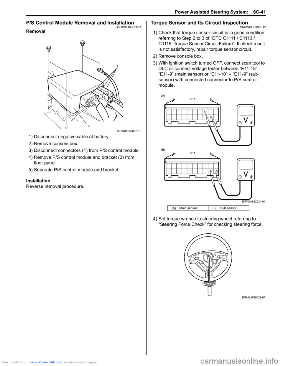
P/S Control Module Removal and InstallationS6RW0D6306011
Removal
1) Disconnect negative cable at battery.
2) Remove console box.
3) Disconnect connectors (1) from P/S control module.
4) Remove P/S control module and bracket (2) from
floor panel.
5) Separate P/S control module and bracket.
Installation
Reverse removal procedure.
Torque Sensor and Its Circuit InspectionS6RW0D6306012
1) Check that torque sensor circuit is in good condition
referring to Step 2 to 3 of “DTC C1111 / C1113 /
C1115: Torque Sensor Circuit Failure”. If check result
is not satisfactory, repair torque sensor circuit.
2) Remove console box.
3) With ignition switch turned OFF, connect scan tool to
DLC or connect voltage tester between “E11-18” –
“E11-9” (main sensor) or “E11-10” – “E11-9” (sub
sensor) with connected connector to P/S control
module.
4) Set torque wrench to steering wheel referring to
“Steering Force Check” for checking steering force.
1
2
I5RW0A630027-01
[A]: Main sensor [B]: Sub sensor
E11
1818
E11
10
[A]
[B]
9 9
I7RW01632021-01
I3RM0A630022-01
Page 940 of 1556
Downloaded from www.Manualslib.com manuals search engine 7A-12 Heater and Ventilation:
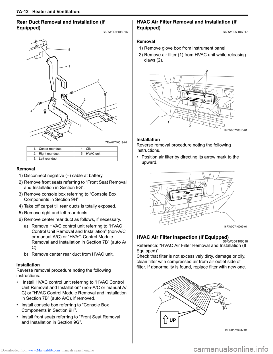
Rear Duct Removal and Installation (If
Equipped)
S6RW0D7106016
Removal
1) Disconnect negative (–) cable at battery.
2) Remove front seats referring to “Front Seat Removal
and Installation in Section 9G”.
3) Remove console box referring to “Console Box
Components in Section 9H”.
4) Take off carpet till rear ducts is totally exposed.
5) Remove right and left rear ducts.
6) Remove center rear duct as follows, if necessary.
a) Remove HVAC control unit referring to “HVAC
Control Unit Removal and Installation” (non-A/C
or manual A/C) or “HVAC Control Module
Removal and Installation in Section 7B” (auto A/
C).
b) Remove center rear duct from HVAC unit.
Installation
Reverse removal procedure noting the following
instructions.
• Install HVAC control unit referring to “HVAC Control
Unit Removal and Installation” (non-A/C or manual A/
C) or “HVAC Control Module Removal and Installation
in Section 7B” (auto A/C), if removed.
• Install console box referring to “Console Box
Components in Section 9H”.
• Install front seats referring to “Front Seat Removal
and Installation in Section 9G”.
HVAC Air Filter Removal and Installation (If
Equipped)
S6RW0D7106017
Removal
1) Remove glove box from instrument panel.
2) Remove air filter (1) from HVAC unit while releasing
claws (2).
Installation
Reverse removal procedure noting the following
instructions.
• Position air filter by directing its arrow mark to the
upward.
HVAC Air Filter Inspection (If Equipped)S6RW0D7106018
Reference: “HVAC Air Filter Removal and Installation (If
Equipped)”
Check that filter is not excessively dirty, damage or oily,
clean filter with compressed air from air outlet side of
filter. If abnormality is found, replace filter with new one.
1. Center rear duct 4. Clip
2. Right rear duct 5. HVAC unit
3. Left rear duct
324 5
1
4
I7RW01710019-01
12
2
I6RW0C710010-01
I6RW0C710009-01
I4RS0A710032-01