cruise control SUZUKI SX4 2006 1.G Service Workshop Manual
[x] Cancel search | Manufacturer: SUZUKI, Model Year: 2006, Model line: SX4, Model: SUZUKI SX4 2006 1.GPages: 1556, PDF Size: 37.31 MB
Page 98 of 1556
Downloaded from www.Manualslib.com manuals search engine 1A-48 Engine General Information and Diagnosis:
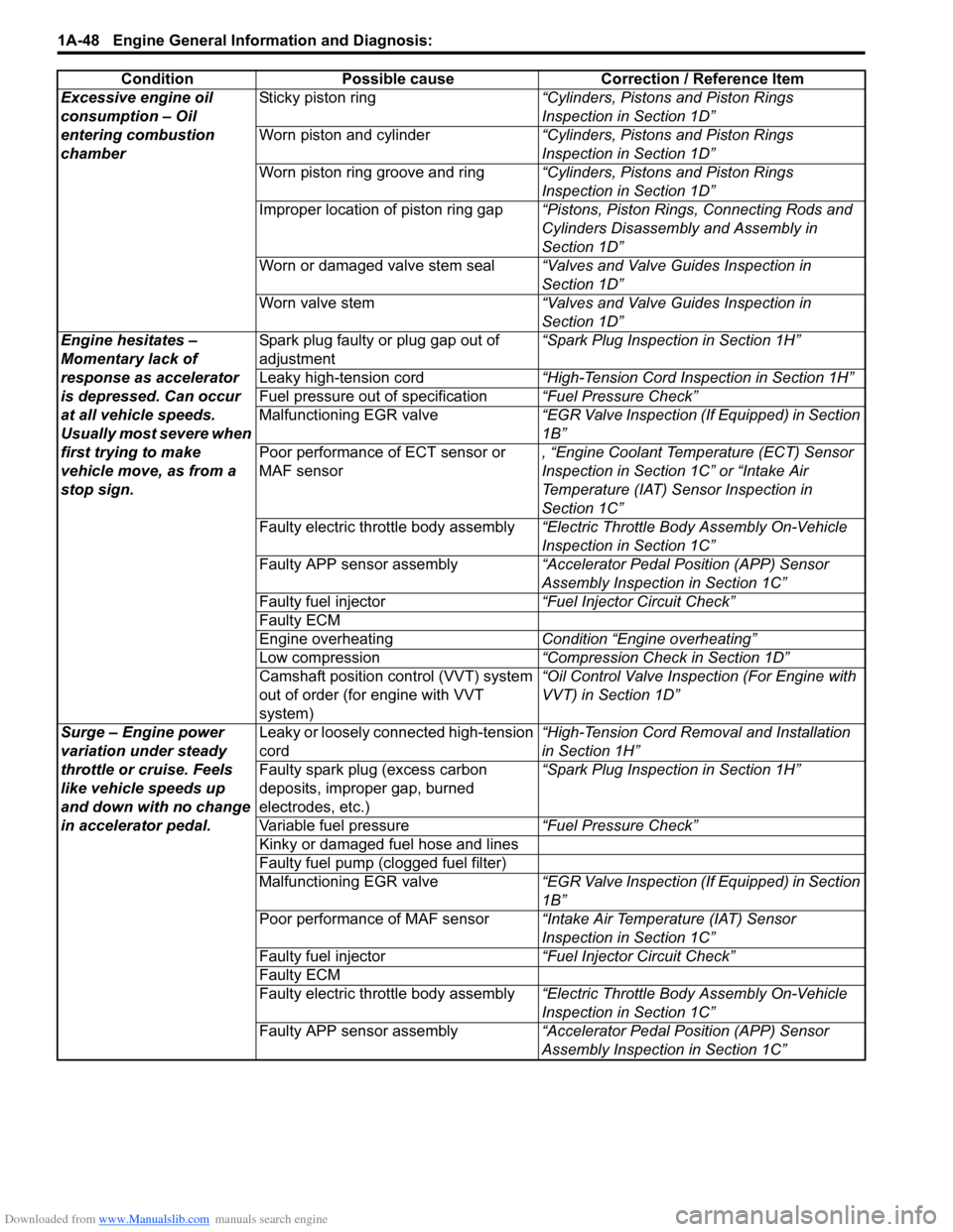
Excessive engine oil
consumption – Oil
entering combustion
chamberSticky piston ring“Cylinders, Pistons and Piston Rings
Inspection in Section 1D”
Worn piston and cylinder“Cylinders, Pistons and Piston Rings
Inspection in Section 1D”
Worn piston ring groove and ring“Cylinders, Pistons and Piston Rings
Inspection in Section 1D”
Improper location of piston ring gap“Pistons, Piston Rings, Connecting Rods and
Cylinders Disassembly and Assembly in
Section 1D”
Worn or damaged valve stem seal“Valves and Valve Guides Inspection in
Section 1D”
Worn valve stem“Valves and Valve Guides Inspection in
Section 1D”
Engine hesitates –
Momentary lack of
response as accelerator
is depressed. Can occur
at all vehicle speeds.
Usually most severe when
first trying to make
vehicle move, as from a
stop sign.Spark plug faulty or plug gap out of
adjustment“Spark Plug Inspection in Section 1H”
Leaky high-tension cord“High-Tension Cord Inspection in Section 1H”
Fuel pressure out of specification“Fuel Pressure Check”
Malfunctioning EGR valve“EGR Valve Inspection (If Equipped) in Section
1B”
Poor performance of ECT sensor or
MAF sensor, “Engine Coolant Temperature (ECT) Sensor
Inspection in Section 1C” or “Intake Air
Temperature (IAT) Sensor Inspection in
Section 1C”
Faulty electric throttle body assembly“Electric Throttle Body Assembly On-Vehicle
Inspection in Section 1C”
Faulty APP sensor assembly“Accelerator Pedal Position (APP) Sensor
Assembly Inspection in Section 1C”
Faulty fuel injector“Fuel Injector Circuit Check”
Faulty ECM
Engine overheatingCondition “Engine overheating”
Low compression“Compression Check in Section 1D”
Camshaft position control (VVT) system
out of order (for engine with VVT
system)“Oil Control Valve Inspection (For Engine with
VVT) in Section 1D”
Surge – Engine power
variation under steady
throttle or cruise. Feels
like vehicle speeds up
and down with no change
in accelerator pedal.Leaky or loosely connected high-tension
cord“High-Tension Cord Removal and Installation
in Section 1H”
Faulty spark plug (excess carbon
deposits, improper gap, burned
electrodes, etc.)“Spark Plug Inspection in Section 1H”
Variable fuel pressure“Fuel Pressure Check”
Kinky or damaged fuel hose and lines
Faulty fuel pump (clogged fuel filter)
Malfunctioning EGR valve“EGR Valve Inspection (If Equipped) in Section
1B”
Poor performance of MAF sensor“Intake Air Temperature (IAT) Sensor
Inspection in Section 1C”
Faulty fuel injector“Fuel Injector Circuit Check”
Faulty ECM
Faulty electric throttle body assembly“Electric Throttle Body Assembly On-Vehicle
Inspection in Section 1C”
Faulty APP sensor assembly“Accelerator Pedal Position (APP) Sensor
Assembly Inspection in Section 1C” Condition Possible cause Correction / Reference Item
Page 1127 of 1556
Downloaded from www.Manualslib.com manuals search engine Air Bag System: 8B-88
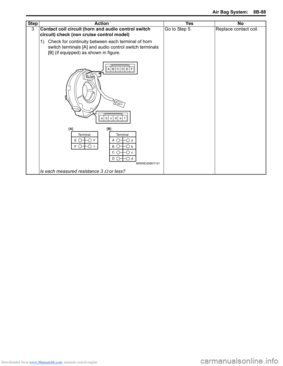
3Contact coil circuit (horn and audio control switch
circuit) check (non cruise control model)
1) Check for continuity between each terminal of horn
switch terminals [A] and audio control switch terminals
[B] (if equipped) as shown in figure.
Is each measured resistance 3
Ω or less?Go to Step 5. Replace contact coil. Step Action Yes No
ABCDEF
abcdef
A
Ba
b
TerminalTerminal
C
Dc
d E
Fe
f
[A] [B]
I6RW0C820017-01
Page 1128 of 1556
Downloaded from www.Manualslib.com manuals search engine 8B-89 Air Bag System:
Inspection of Intermittent and Poor
Connections
S6RW0D8204047
Most intermittents are caused by faulty electrical
connections or wiring. When a check for proper
connection is requested in a diagnostic flow, perform
careful check of suspect circuits.
If any abnormality is found, repair or replace as a wire
harness assembly.
• Poor mating of connector halves, or terminals not fully
seated in the connector body (backed out).• Dirt or corrosion on the terminals. The terminals must
be clean and free of any foreign material which could
impede proper terminal contact.
However, cleaning the terminal with a sand paper or
the like is prohibited.
• Damaged connector body, exposing the terminals to
moisture and dirt, as well as not maintaining proper
terminal orientation with the component or mating
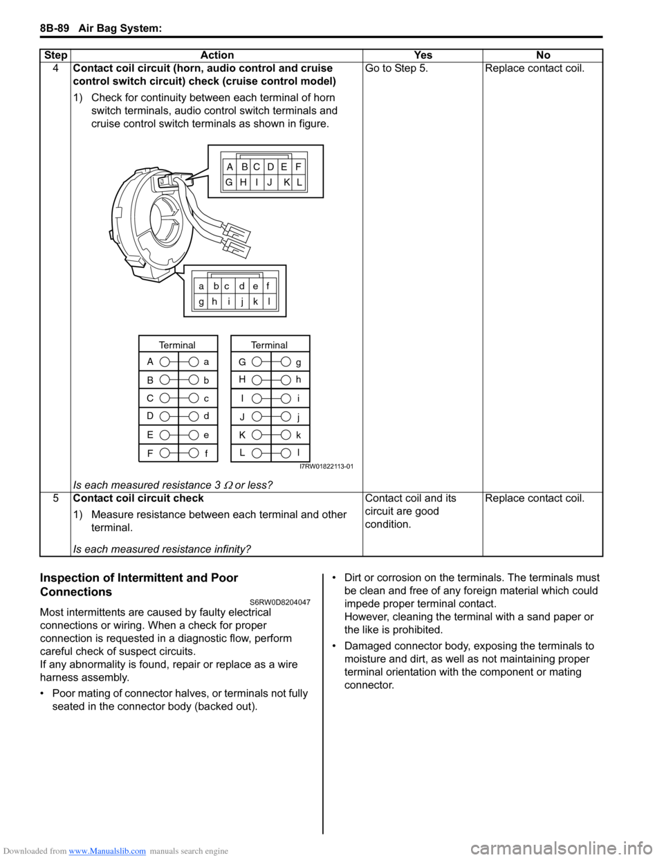
connector. 4Contact coil circuit (horn, audio control and cruise
control switch circuit) check (cruise control model)
1) Check for continuity between each terminal of horn
switch terminals, audio control switch terminals and
cruise control switch terminals as shown in figure.
Is each measured resistance 3
Ω or less?Go to Step 5. Replace contact coil.
5Contact coil circuit check
1) Measure resistance between each terminal and other
terminal.
Is each measured resistance infinity?Contact coil and its
circuit are good
condition.Replace contact coil. Step Action Yes No
ABCDEF
GH I J KL
a bc def
gh i j k l
A
B
C
Da
b
c
d
Terminal
E
Fe
f
I
J
K
Li
j
k
l
Terminal
G
Hg
h
I7RW01822113-01
Page 1189 of 1556
Downloaded from www.Manualslib.com manuals search engine Wiring Systems: 9A-22
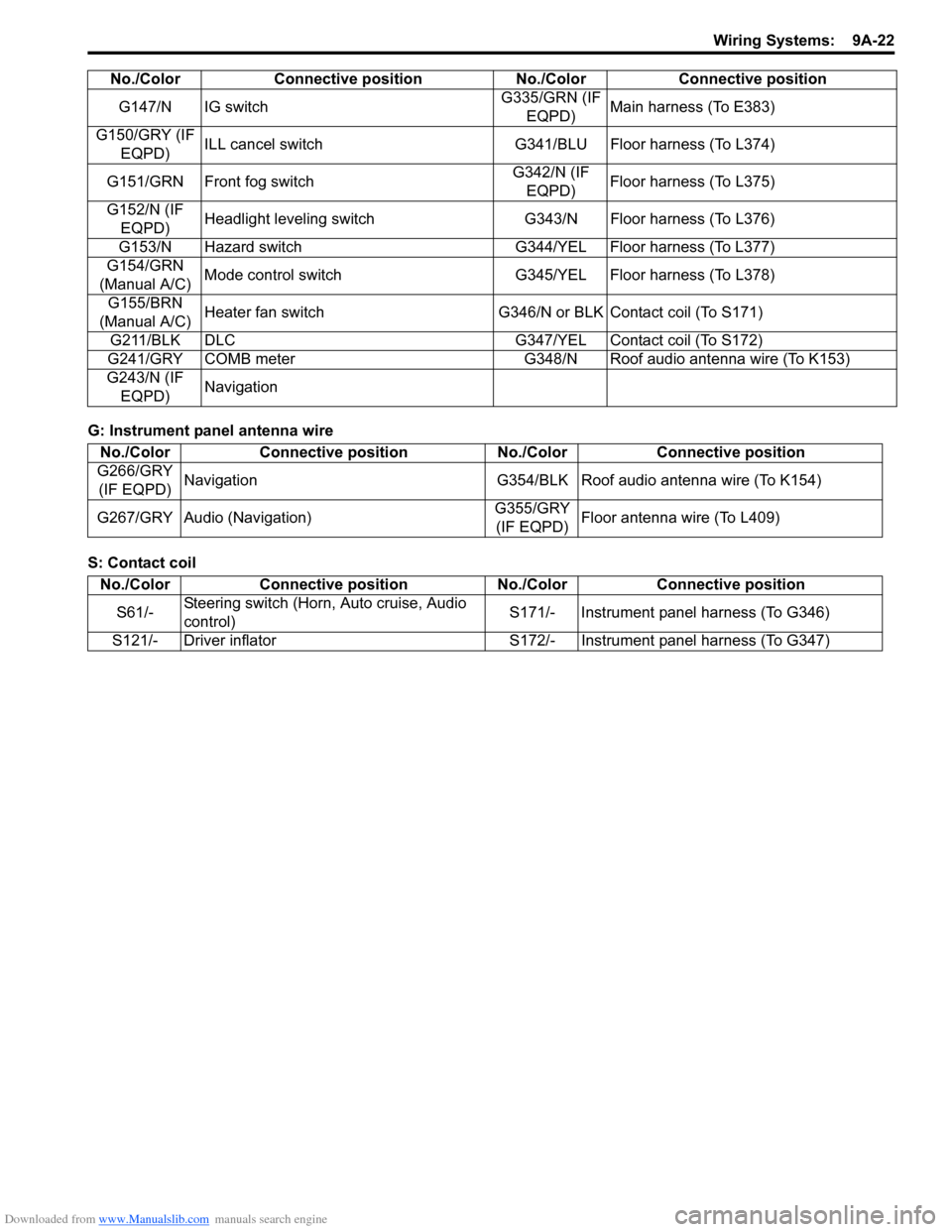
G: Instrument panel antenna wire
S: Contact coilG147/N IG switchG335/GRN (IF
EQPD)Main harness (To E383)
G150/GRY (IF
EQPD)ILL cancel switch G341/BLU Floor harness (To L374)
G151/GRN Front fog switchG342/N (IF
EQPD)Floor harness (To L375)
G152/N (IF
EQPD)Headlight leveling switch G343/N Floor harness (To L376)
G153/N Hazard switch G344/YEL Floor harness (To L377)
G154/GRN
(Manual A/C)Mode control switch G345/YEL Floor harness (To L378)
G155/BRN
(Manual A/C)Heater fan switch G346/N or BLK Contact coil (To S171)
G211/BLK DLC G347/YEL Contact coil (To S172)
G241/GRY COMB meter G348/N Roof audio antenna wire (To K153)
G243/N (IF
EQPD)Navigation No./Color Connective position No./Color Connective position
No./Color Connective position No./Color Connective position
G266/GRY
(IF EQPD)Navigation G354/BLK Roof audio antenna wire (To K154)
G267/GRY Audio (Navigation)G355/GRY
(IF EQPD)Floor antenna wire (To L409)
No./Color Connective position No./Color Connective position
S61/-Steering switch (Horn, Auto cruise, Audio
control)S171/- Instrument panel harness (To G346)
S121/- Driver inflator S172/- Instrument panel harness (To G347)
Page 1241 of 1556

Downloaded from www.Manualslib.com manuals search engine Wiring Systems: 9A-74
G333
E381S171
G346161514
GWGY
J/B
2
15ASTOP
30
15ADOME
37
E0120
GRN/WHT
GRN/WHT
GRN
12
10AIG1 SIG
26
LT GRN/BLK
8
GRN/YEL
622RED/WHTLT GRN21BLK/YEL
RED/WHT
RED/BLK
LT GRNBLK/YEL
RB
E325 E323 E325 E3234
15AIG COIL
20
5
E181
3 4Brake
light
switch
MAIN RESUME/
ACCEL SET/
COAST CANCEL
1 2
S61
12
Steering
switch
(Auto
cruise
switch)
Contact
coilContact
coil
11 610
121110
6
Cruise control (IF EQPD)
ECM
2
CMP
sensor
C01
BLK
34
1529 3031
3C32
52C01 E0122302813
RED/YEL
PNK/BLUBLKBLKBLKBLK
BLK/RED
12
J/B
E3251
2
"C-2"
G346
S171
YG
YEL/GRNYEL/BLKWHT/REDWHTYEL/RED
Starting
motor
relay Starting
motor
relay
"A-1"ICM
"A-7"YBYR
2
W"A-1"
E01
LT GRN/BLK
BLK
BLKBLK
7C019
CPP
cut
switch
E1921
2
79
BLK/ORNBLK/ORN
BLK/ORN
Current
sensor
C461
23
Weld
splice
C312
BLK/WHT
I6RW0C910946-04
Page 1290 of 1556

Downloaded from www.Manualslib.com manuals search engine 9A-123 Wiring Systems:
D-7 Brake Light System Circuit DiagramS6RW0D910E028
Brake
light
switch
Shift lock
relay
(R)
Brake light
GRNLT GRN/BLK
BLK
(L)
E181
L134
GRN/WHT
GRN/WHT
GRN/WHTGRN/WHT
5
L315
E325
J/B
"F-2"
ABS
Cont.M
GRN/WHT
2 2 1
"A-5"
ECM
21
GW
GW
GRN/YEL
"A-5"
ECM
GY
GW
42
31
J/B
L1332
52
1
GRN/WHT
"A-6"
GW
O92
High mounted
stop light
201918
BLKBLK
BLKBLKBLK
23
BLK
BLK
2
GRN/WHTGRN/WHTGRN/WHT
E3232
L393
L2331
O233
L3932
L390
O2312 15A
30STOP
E32512 10A
26IG1 SIG
Cruise control
(IF EQPD)
I6RW0C910A15-01
Page 1306 of 1556
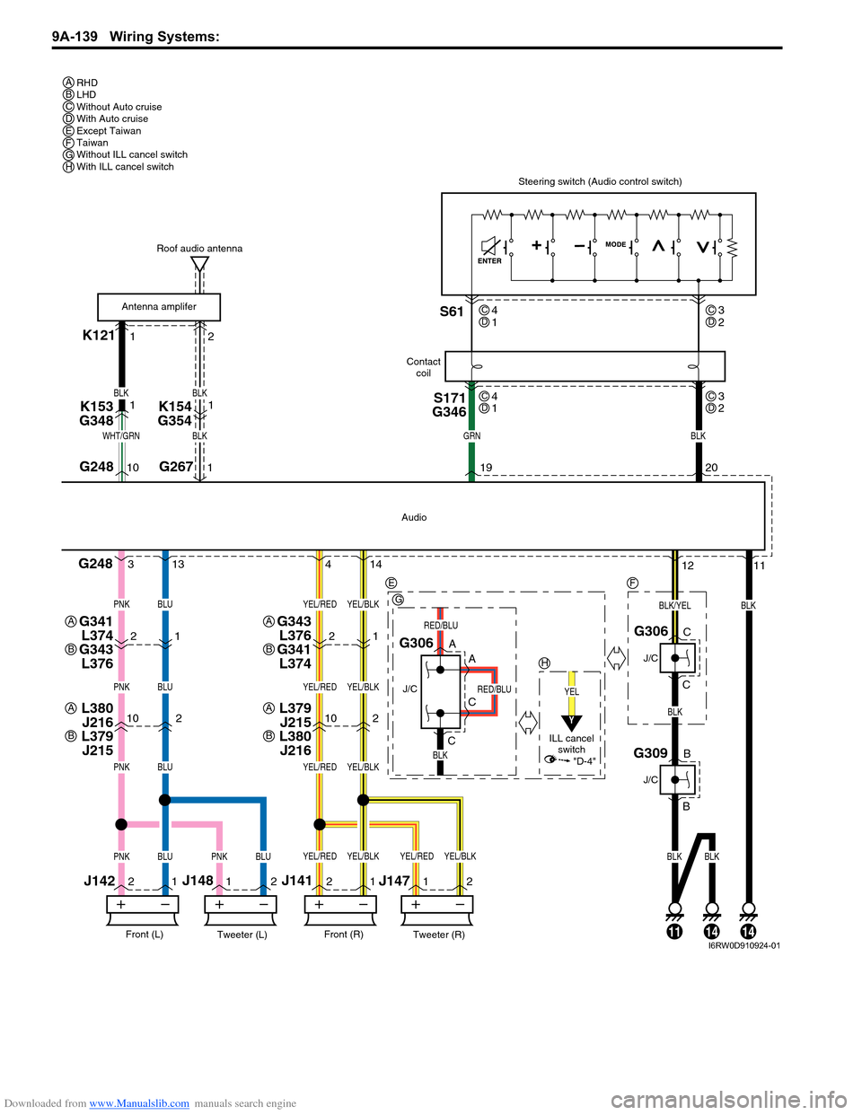
Downloaded from www.Manualslib.com manuals search engine 9A-139 Wiring Systems:
K12112
102102
2
11
22
11
211
G248
G248
BLK
Tweeter (L)Front (L)
J142J148
Tweeter (R)Front (R)
J141
J147
BLK
YEL
BLK
Audio
G306
J/C
ILL cancel
switch
A
A
C
C
G306
J/C
C
C
Steering switch (Audio control switch)
19G26710 120
BLKGRNWHT/GRN
BLK
BLUPNK
BLUPNK
BLUPNK
BLUBLKBLKBLUPNKPNK
YEL/BLKYEL/RED
YEL/BLKYEL/RED
YEL/BLKYEL/RED
YEL/BLKYEL/BLKYEL/REDYEL/RED
S171
G346S61
Roof audio antenna
Contact
coil
Antenna amplifer
4 313 14
K153
G3481
BLK
BLK
K154
G3541
21
G343
L376
G341
L3742112
BLK/YEL
RED/BLU
RED/BLU
G309
J/C
B
B
141114
RHD
LHD
Without Auto cruise
With Auto cruise
Except Taiwan
Taiwan
Without ILL cancel switch
With ILL cancel switch A
E
G
H
A
B
G341
L374
G343
L376A
B
L379
J215
L380
J216A
B
L380
J216
L379
J215A
B
F
BCDEFGH
4
1CD3
2CD
4
1CD3
2CD
Y
"D-4"
I6RW0D910924-01
Page 1374 of 1556
Downloaded from www.Manualslib.com manuals search engine 9C-22 Instrumentation / Driver Info. / Horn:
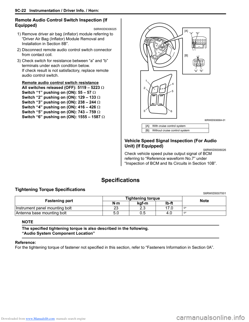
Remote Audio Control Switch Inspection (If
Equipped)
S6RW0D9306025
1) Remove driver air bag (inflator) module referring to
“Driver Air Bag (Inflator) Module Removal and
Installation in Section 8B”.
2) Disconnect remote audio control switch connector
from contact coil.
3) Check switch for resistance between “a” and “b”
terminals under each condition below.
If check result is not satisfactory, replace remote
audio control switch.
Remote audio control switch resistance
All switches released (OFF): 5119 – 5223 Ω
Switch “1” pushing on (ON): 55 – 57 Ω
Switch “2” pushing on (ON): 129 – 133 Ω
Switch “3” pushing on (ON): 238 – 244 Ω
Switch “4” pushing on (ON): 416 – 426 Ω
Switch “5” pushing on (ON): 743 – 759 Ω
Switch “6” pushing on (ON): 1555 – 1587 Ω
Vehicle Speed Signal Inspection (For Audio
Unit) (If Equipped)
S6RW0D9306026
Check vehicle speed pulse output signal of BCM
referring to “Reference waveform No.7” under
“Inspection of BCM and Its Circuits in Section 10B”.
Specifications
Tightening Torque SpecificationsS6RW0D9307001
NOTE
The specified tightening torque is also described in the following.
“Audio System Component Location”
Reference:
For the tightening torque of fastener not specified in this section, refer to “Fasteners Information in Section 0A”.
[A]: With cruise control system
[B]: Without cruise control system
1
2
34
5
6
“b” “a”
“b” “a” [A]
[B]
I6RW0D930004-01
Fastening partTightening torque
Note
N⋅mkgf-mlb-ft
Instrument panel mounting bolt 23 2.3 17.0�)
Antenna base mounting bolt 5.0 0.5 4.0�)