heating SUZUKI SX4 2010 1.G Owners Manual
[x] Cancel search | Manufacturer: SUZUKI, Model Year: 2010, Model line: SX4, Model: SUZUKI SX4 2010 1.GPages: 297, PDF Size: 4.51 MB
Page 12 of 297
ILLUSTRATED TABLE OF CONTENTS
80J23-03E
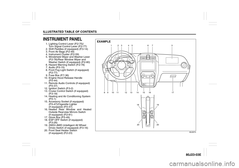
INSTRUMENT PANEL1. Lighting Control Lever (P.2-75)/
Turn Signal Control Lever (P.2-77)
2. Shift Paddles (if equipped) (P.3-14)
3. Front Air Bags (P.2-49)
4. Instrument Cluster (P.2-59)
5. Windshield Wiper and Washer Lever
(P.2-78)/Rear Window Wiper and
Washer Switch (if equipped) (P.2-80)
6. Hazard Warning Switch (P.2-78)
7. Audio (P.5-15)
8. Front Fog Light Switch (if equipped)
(P.2-77)
9. Fuse Box (P.7-36)
10. Engine Hood Release Handle
(P.5-44)
11. Remote Audio Controls (if equipped)
(P.5-37)
12. Ignition Switch (P.3-2)
13. Cruise Control Switch (if equipped)
(P.3-18)
14. Heating and Air Conditioning System
(P.5-1)
15. Accessory Socket (if equipped)
(P.5-47)/Cigarette Lighter
(if equipped) (P.5-47)
16. Heated Rear Window and Heated
Outside Rearview Mirrors Switch
(if equipped) (P.2-81)
17. Glove Box (P.5-49)
18. ESP OFF Switch (if equipped)
(P.3-26)
19. 2WD/i-AWD (intelligent All Wheel
Drive) Switch (if equipped) (P.3-16)
20. Front Seat Heater Switch
(if equipped) (P.2-23)
80J2074
1
9
18
3 2
4
5
6
7
3
12
13
14
15
16
17
10
11
8
19
20
20
EXAMPLE
Page 41 of 297
2-24
BEFORE DRIVING
80J23-03E
86G064
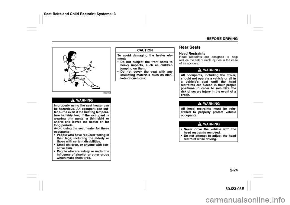
Rear SeatsHead RestraintsHead restraints are designed to help
reduce the risk of neck injuries in the case
of an accident.
WARNING
Improperly using the seat heater can
be hazardous. An occupant can suf-
fer burns even if the heating tempera-
ture is fairly low, if the occupant is
wearing thin pants, a thin skirt or
shorts and leaves the heater on for
long periods.
Avoid using the seat heater for these
occupants:
People who have reduced feeling in
their legs, including the elderly or
those with certain disabilities.
Small children, or anyone with sen-
sitive skin.
People who are asleep or under the
influence of alcohol or other drugs
which make them tired.
CAUTION
To avoid damaging the heater ele-
ment:
Do not subject the front seats to
heavy impacts, such as children
jumping on them.
Do not cover the seat with any
insulating materials such as blan-
kets or cushions.
WARNING
All occupants, including the driver,
should not operate a vehicle or sit in
a vehicle’s seat until the head
restraints are placed in their proper
positions in order to minimize the
risk of severe injury in the event of a
crash.
WARNING
All head restraints must be rein-
stalled to properly protect vehicle
occupants.
WARNING
Never drive the vehicle with the
head restraints removed.
Do not attempt to adjust the head
restraint while driving.
Seat Belts and Child Restraint Systems: 3
Page 87 of 297
2-70
BEFORE DRIVING
80J23-03E
Temperature Gauge
80JM103
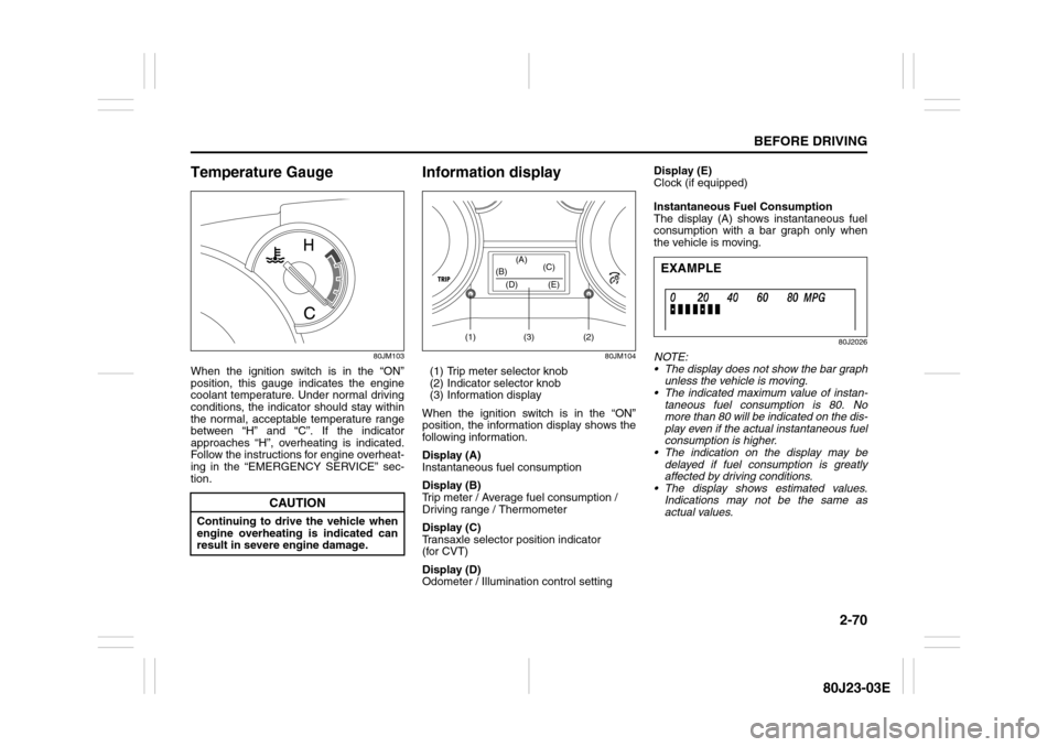
When the ignition switch is in the “ON”
position, this gauge indicates the engine
coolant temperature. Under normal driving
conditions, the indicator should stay within
the normal, acceptable temperature range
between “H” and “C”. If the indicator
approaches “H”, overheating is indicated.
Follow the instructions for engine overheat-
ing in the “EMERGENCY SERVICE” sec-
tion.
Information display
80JM104
(1) Trip meter selector knob
(2) Indicator selector knob
(3) Information display
When the ignition switch is in the “ON”
position, the information display shows the
following information.
Display (A)
Instantaneous fuel consumption
Display (B)
Trip meter / Average fuel consumption /
Driving range / Thermometer
Display (C)
Transaxle selector position indicator
(for CVT)
Display (D)
Odometer / Illumination control settingDisplay (E)
Clock (if equipped)
Instantaneous Fuel Consumption
The display (A) shows instantaneous fuel
consumption with a bar graph only when
the vehicle is moving.
80J2026
NOTE:
The display does not show the bar graph
unless the vehicle is moving.
The indicated maximum value of instan-
taneous fuel consumption is 80. No
more than 80 will be indicated on the dis-
play even if the actual instantaneous fuel
consumption is higher.
The indication on the display may be
delayed if fuel consumption is greatly
affected by driving conditions.
The display shows estimated values.
Indications may not be the same as
actual values.
CAUTION
Continuing to drive the vehicle when
engine overheating is indicated can
result in severe engine damage.
(1) (2)(3) (D) (B)(A)
(C)
(E)
EXAMPLE
Page 108 of 297
3-7OPERATING YOUR VEHICLE
80J23-03E
For CVT vehicles, always set the parking
brake before moving the gearshift lever to
the “P” (Park) position. If you park on an
incline and shift into “P” before you set the
parking brake, the weight of the vehicle
may make it difficult to shift out of “P” when
you are ready to drive the vehicle. When
preparing to drive the vehicle, move the
gearshift lever out of the “P” position before
releasing the parking brake.
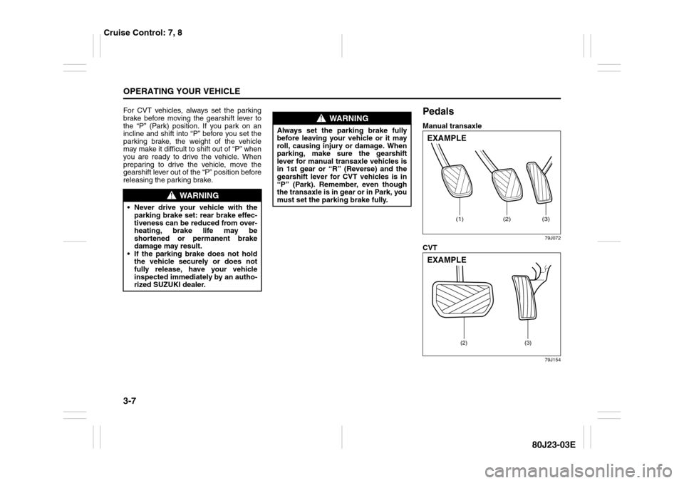
PedalsManual transaxle
79J072
CVT
79J154
WARNING
Never drive your vehicle with the
parking brake set: rear brake effec-
tiveness can be reduced from over-
heating, brake life may be
shortened or permanent brake
damage may result.
If the parking brake does not hold
the vehicle securely or does not
fully release, have your vehicle
inspected immediately by an autho-
rized SUZUKI dealer.
WARNING
Always set the parking brake fully
before leaving your vehicle or it may
roll, causing injury or damage. When
parking, make sure the gearshift
lever for manual transaxle vehicles is
in 1st gear or “R” (Reverse) and the
gearshift lever for CVT vehicles is in
“P” (Park). Remember, even though
the transaxle is in gear or in Park, you
must set the parking brake fully.
(1)
(2)
(3)
EXAMPLE
(2) (3)
EXAMPLE
Cruise Control: 7, 8
Page 109 of 297
3-8
OPERATING YOUR VEHICLE
80J23-03E
Clutch Pedal (1)(For manual transaxle)
The clutch pedal is used to disengage the
drive to the wheels when starting the
engine, stopping or shifting the gearshift
lever. Depressing the pedal disengages
the clutch.Brake Pedal (2)Your SUZUKI vehicle is equipped with
either front and rear disc brakes or front
disc brakes and rear drum brakes.
Depressing the brake pedal applies both
sets of brakes.
You may hear occasional brake squeal
when you apply the brakes. This is a nor-
mal condition caused by environmental
factors such as cold, wet, snow, etc.
Accelerator Pedal (3)This pedal controls the speed of the
engine. Depressing the accelerator pedal
increases power output and speed.
Starting the EngineBefore Starting the Engine1) Make sure the parking brake is set fully.
2) Manual Transaxle – Shift into “N” (Neu-
tral) and depress the clutch pedal all
the way to the floor. Hold the clutch
pedal while starting the engine.
CVT – If the gearshift lever is not in “P”
(Park) position, shift into “P”. (If you
need to re-start the engine while the
vehicle is moving, shift into “N”.)
NOTE:
The engine of manual transaxle vehicle will
not start unless the clutch pedal is
depressed.
NOTE:
CVT vehicles have a starter interlock
device which is designed to keep the
starter from operating if the transaxle is in
any of the drive positions.
CAUTION
Do not drive with your foot resting on
the clutch pedal. It could result in
excessive clutch wear, clutch dam-
age, or unexpected loss of engine
braking.
WARNING
If brake squeal is excessive and
occurs each time the brakes are
applied, you should have the brakes
checked by your SUZUKI dealer.
WARNING
Do not “ride” the brakes by applying
them continuously or resting your
foot on the pedal. This will result in
overheating of the brakes which
could cause unpredictable braking
action, longer stopping distances or
permanent brake damage.
WARNING
Make sure that the parking brake is
set fully and the transaxle is in Neu-
tral (or Park for vehicles with a CVT)
before attempting to start the engine.
Cruise Control: 7, 8
Remote Audio Controls:
Horn: 6
Page 110 of 297
3-9OPERATING YOUR VEHICLE
80J23-03E
Starting a Cold EngineWith your foot off the accelerator pedal,
crank the engine by turning the ignition key
to “START”. Release the key when the
engine starts.
If the engine does not start after 15 sec-
onds of cranking, wait about 15 seconds,
then press down the accelerator pedal to
1/3 of its travel and try cranking the engine
again. Release the key and accelerator
pedal when the engine starts.
If the engine still does not start, try holding
the accelerator pedal all the way to the
floor while cranking. This should clear the
engine if it is flooded.
If you are unable to start the engine using
this procedure, consult your SUZUKI
dealer.Starting a Warm EngineUse the same procedure as for “Starting a
Cold Engine”.
Engine Block Heater
(if equipped)
80J2064
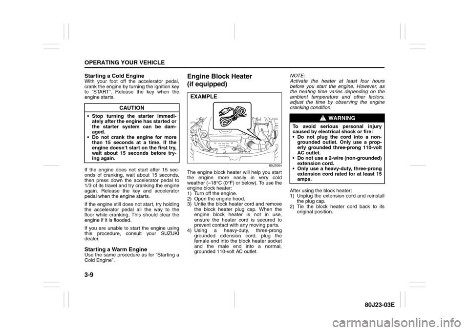
The engine block heater will help you start
the engine more easily in very cold
weather (–18°C (0°F) or below). To use the
engine block heater:
1) Turn off the engine.
2) Open the engine hood.
3) Untie the block heater cord and remove
the block heater plug cap. When the
engine block heater is not in use,
ensure the heater cord is secured to
prevent contact with any moving parts.
4) Using a heavy-duty, three-prong
grounded extension cord, plug the
female end into the block heater socket
and the male end into a normal,
grounded 110-volt AC outlet.NOTE:
Activate the heater at least four hours
before you start the engine. However, as
the heating time varies depending on the
ambient temperature and other factors,
adjust the time by observing the engine
cranking condition.
After using the block heater:
1) Unplug the extension cord and reinstall
the plug cap.
2) Tie the block heater cord back to its
original position.
CAUTION
Stop turning the starter immedi-
ately after the engine has started or
the starter system can be dam-
aged.
Do not crank the engine for more
than 15 seconds at a time. If the
engine doesn’t start on the first try,
wait about 15 seconds before try-
ing again.
EXAMPLE
WARNING
To avoid serious personal injury
caused by electrical shock or fire:
Do not plug the cord into a non-
grounded outlet. Only use a prop-
erly grounded three-prong 110-volt
AC outlet.
Do not use a 2-wire (non-grounded)
extension cord.
Only use a heavy-duty, three-prong
extension cord rated for at least 15
amps.
Page 134 of 297
4-1DRIVING TIPS
80J23-03E
52D078S
Break-In Catalytic Converter
68KM085
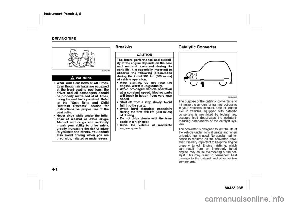
The purpose of the catalytic converter is to
minimize the amount of harmful pollutants
in your vehicle’s exhaust. Use of leaded
fuel in vehicles equipped with catalytic
converters is prohibited by federal law,
because lead deactivates the pollutant-
reducing components of the catalyst sys-
tem.
The converter is designed to last the life of
the vehicle under normal usage and when
unleaded fuel is used. No special mainte-
nance is required on the converter. How-
ever, it is very important to keep the engine
properly tuned. Engine misfiring, which
can result from an improperly tuned
engine, may cause overheating of the cat-
alyst. This may result in permanent heat
damage to the catalyst and other vehicle
components.
WARNING
Wear Your Seat Belts at All Times.
Even though air bags are equipped
at the front seating positions, the
driver and all passengers should
be properly restrained at all times,
using the seat belts provided. Refer
to the “Seat Belts and Child
Restraint Systems” section for
instructions on proper use of the
seat belts.
Never drive while under the influ-
ence of alcohol or other drugs.
Alcohol and drugs can seriously
impair your ability to drive safely,
greatly increasing the risk of injury
to yourself and others. You should
also avoid driving when you are
tired, sick, irritated or under stress.
CAUTION
The future performance and reliabil-
ity of the engine depends on the care
and restraint exercised during its
early life. It is especially important to
observe the following precautions
during the initial 960 km (600 miles)
of vehicle operation.
After starting, do not race the
engine. Warm it up gradually.
Avoid prolonged vehicle operation
at a constant speed. Moving parts
will break in better if you vary your
speed.
Start off from a stop slowly. Avoid
full throttle starts.
Avoid hard stopping, especially
during the first 320 km (200 miles)
of driving.
Do not drive slowly with the tran-
saxle in a high gear.
Drive the vehicle at moderate
engine speeds.
Instrument Panel: 3, 8
Page 138 of 297
4-5DRIVING TIPS
80J23-03E
Tire ChainsTire chains should only be used if they are
needed to increase traction or are required
by law. Make sure that the chains you use
are small-link chains or cable-type chains
and are the correct size for your vehicle’s
tires. Also make sure that there is enough
clearance between the fenders and the
chains as installed on the tires.
Install the chains on the front tires tightly,
according to the chain manufacturer’s
instructions. Retighten the chains after
driving about 1.0 km (1/2 mile) if neces-
sary. With the chains installed, drive slowly.Do not drive through deep or rushing
water
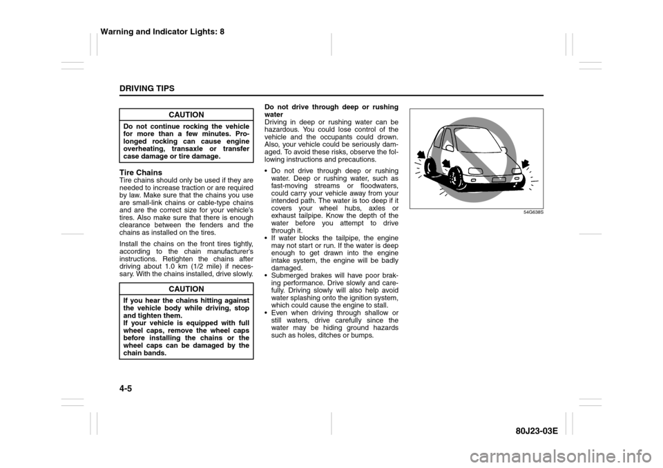
Driving in deep or rushing water can be
hazardous. You could lose control of the
vehicle and the occupants could drown.
Also, your vehicle could be seriously dam-
aged. To avoid these risks, observe the fol-
lowing instructions and precautions.
Do not drive through deep or rushing
water. Deep or rushing water, such as
fast-moving streams or floodwaters,
could carry your vehicle away from your
intended path. The water is too deep if it
covers your wheel hubs, axles or
exhaust tailpipe. Know the depth of the
water before you attempt to drive
through it.
If water blocks the tailpipe, the engine
may not start or run. If the water is deep
enough to get drawn into the engine
intake system, the engine will be badly
damaged.
Submerged brakes will have poor brak-
ing performance. Drive slowly and care-
fully. Driving slowly will also help avoid
water splashing onto the ignition system,
which could cause the engine to stall.
Even when driving through shallow or
still waters, drive carefully since the
water may be hiding ground hazards
such as holes, ditches or bumps.
54G638S
CAUTION
Do not continue rocking the vehicle
for more than a few minutes. Pro-
longed rocking can cause engine
overheating, transaxle or transfer
case damage or tire damage.
CAUTION
If you hear the chains hitting against
the vehicle body while driving, stop
and tighten them.
If your vehicle is equipped with full
wheel caps, remove the wheel caps
before installing the chains or the
wheel caps can be damaged by the
chain bands.
Warning and Indicator Lights: 8
Page 141 of 297
OTHER CONTROLS AND EQUIPMENT
5
80J23-03E
60G407
OTHER CONTROLS AND EQUIPMENTHeating and Air Conditioning System ............................... 5-1
Radio Antenna ..................................................................... 5-15
Audio Systems .................................................................... 5-15
Fuel Filler Cap ..................................................................... 5-43
Engine Hood ........................................................................ 5-44
Sun Visor ............................................................................. 5-45
Interior Light Switch ........................................................... 5-45
Luggage Compartment Light (SX4) ................................... 5-46
Trunk Light (SX4 SEDAN) ................................................... 5-46
Spot Light ............................................................................ 5-47
Accessory Socket (if equipped) ......................................... 5-47
Cigarette Lighter and Ashtray (if equipped) ..................... 5-47
Assist Grips (if equipped) .................................................. 5-48
Glove Box ............................................................................ 5-49
Cup Holder and Storage Area (if equipped) ..................... 5-49
Front Seat Back Pocket (if equipped) ............................... 5-50
Armrest (if equipped) .......................................................... 5-51
Shopping Hook (if equipped) ............................................. 5-51
Floor Mats (if equipped) ..................................................... 5-51
Luggage Compartment Cover (if equipped) ..................... 5-52
Luggage Compartment Board (if equipped) ..................... 5-53
Roof Rails or Roof Rack Anchors (if equipped) ............... 5-55
Frame Hooks ....................................................................... 5-56
Page 142 of 297
5-1OTHER CONTROLS AND EQUIPMENT
80J23-03E
Heating and Air Conditioning
SystemThere are three types of heating and air
conditioning systems as follows:
Heating System
Manual Heating and Air Conditioning
System
Automatic Heating and Air Conditioning
System (Climate Control)
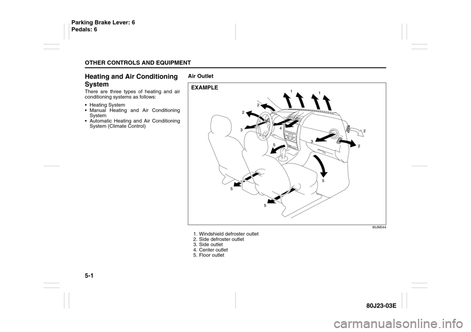
Air Outlet
80JM044
1. Windshield defroster outlet
2. Side defroster outlet
3. Side outlet
4. Center outlet
5. Floor outletEXAMPLE
Parking Brake Lever: 6
Pedals: 6