rear view mirror TOYOTA AVALON 2017 XX40 / 4.G User Guide
[x] Cancel search | Manufacturer: TOYOTA, Model Year: 2017, Model line: AVALON, Model: TOYOTA AVALON 2017 XX40 / 4.GPages: 492, PDF Size: 7.17 MB
Page 131 of 492
1313-4. Adjusting the steering wheel and mirrors
3
Operation of each component
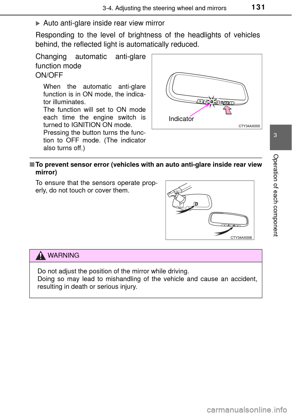
Auto anti-glare inside rear view mirror
Responding to the level of brightne ss of the headlights of vehicles
behind, the reflected light is automatically reduced.
Changing automatic anti-glare
function mode
ON/OFF
When the automatic anti-glare
function is in ON mode, the indica-
tor illuminates.
The function will set to ON mode
each time the engine switch is
turned to IGNITION ON mode.
Pressing the button turns the func-
tion to OFF mode. (The indicator
also turns off.)
■ To prevent sensor error (vehicles with an auto anti-glare inside rear view
mirror)
Indicator
To ensure that the sensors operate prop-
erly, do not touch or cover them.
WARNING
Do not adjust the position of the mirror while driving.
Doing so may lead to mishandling of the vehicle and cause an accident,
resulting in death or serious injury.
Page 132 of 492
1323-4. Adjusting the steering wheel and mirrors
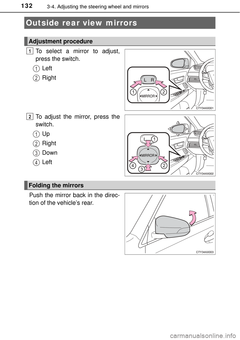
To select a mirror to adjust,
press the switch.Left
Right
To adjust the mirror, press the
switch. Up
Right
Down
Left
Push the mirror back in the direc-
tion of the vehicle’s rear.
Outside rear view mirrors
Adjustment procedure
1
1
2
2
1
2
3
4
Folding the mirrors
Page 133 of 492
1333-4. Adjusting the steering wheel and mirrors
3
Operation of each component
When the mirror select switch is in the L or R position, the outside rear
view mirrors will automatically angle downwards when the vehicle is
reversing in order to give a better view of the ground.
To disable this function, move the mirror select switch to the neutral
position (between L and R).
■Adjusting the mirror angle when the vehicle is reversing
With the shift lever in R, adjust the mirror angle at a desired posi-
tion. The adjusted angle will be me morized and the mirror will auto-
matically tilt to the memorized angle whenever the shift lever is
shifted to R from next time.
The memorized downward tilt position of the mirror is linked to the nor-
mal position (angle adjusted with the shift lever in other than R). There-
fore, if the normal position is changed after adjustment, the tilt position
will also change.
If the normal position is changed, readjust the tilt down angle.
■ Mirror angle can be adjusted when
The engine switch is in ACCESSORY or IGNITION ON mode.
■ When the mirrors are fogged up
The outside rear view mirrors can be cleared using the mirror defoggers. Turn
on the rear window defogger to turn on the outside rear view mirror defog-
gers. ( →P. 264)
■ Automatic adjustment of the mirror angle (vehicles with driving position
memory)
A desired mirror face angle can be entered to memory and recalled automati-
cally by the driving position memory. ( →P. 121)
■ Auto anti-glare function (vehicles with outer foot lights)
When the anti-glare inside rear view mirr or is set to automatic mode, the out-
side rear view mirrors will activate in conjunction with the anti-glare inside
rear view mirror to reduce reflected light. ( →P. 130)
Linked mirror function when reversing (vehicles with driving
position memory)
Page 134 of 492

1343-4. Adjusting the steering wheel and mirrors
WARNING
■Important points while driving
Observe the following precautions while driving.
Failure to do so may result in loss of control of the vehicle and cause an
accident, resulting in death or serious injury.
● Do not adjust the mirrors while driving.
● Do not drive with the mirrors folded.
● Both the driver and passenger side mirrors must be extended and properly
adjusted before driving.
■ When a mirror is moving
To avoid personal injury and mirror malfunction, be careful not to get your
hand caught by the moving mirror.
■ When the mirror de foggers are operating
Do not touch the rear view mirror surfaces, as they can become very hot
and burn you.
Page 147 of 492
1474-1. Before driving
4
Driving
WARNING
Observe the following precautions.
Failure to do so may result in death or serious injury.
■When driving the vehicle
● During normal driving, do not turn off the engine. Turning the engine off
while driving will not cause loss of steering or braking control, but the
power assist to these systems will be lost. This will make it more difficult to
steer and brake, so you should pull over and stop the vehicle as soon as it
is safe to do so.
However, in the event of an emergency, such as if it becomes impossible
to stop the vehicle in the normal way: →P. 381
● Use engine braking (downshift) to maintain a safe speed when driving
down a steep hill.
Using the brakes continuously may cause the brakes to overheat and lose
effectiveness. ( →P. 165)
● Do not adjust the positions of the steering wheel, the seat, or the inside or
outside rear view mirrors while driving.
Doing so may result in a loss of vehicle control.
● Always check that all passengers’ arms, heads or other parts of their body
are not outside the vehicle.
● Do not drive in excess of the speed limit. Even if the legal speed limit per-
mits it, do not drive over 85 mph (140 km/h) unless your vehicle has h\
igh-
speed capability tires. Driving over 85 mph (140 km/h) may result in tire
failure, loss of control and possible injury. Be sure to consult a tire dealer
to determine whether the tires on your vehicle are high-speed capability
tires or not before driving at such speeds.
Page 179 of 492
1794-3. Operating the lights and wipers
4
Driving
●In the situations shown below, the system may not be able to accurately
detect surrounding brightness levels. This may cause the low beams to
remain on or the high beams to cause problems for pedestrians, vehicles
ahead or other parties. In these cases, manually switch between the high
and low beams.
• In bad weather (rain, snow, fog, sandstorms etc.)
• The windshield is obscured by fog, mist, ice, dirt etc.
• The windshield is cracked or damaged.
• The inside rear view mirror or ca mera sensor is deformed or dirty.
• The camera sensor temperature is extremely high.
• Surrounding brightness levels are equal to those of headlights, tail lights or fog lights.
• Vehicles ahead have headlights that are either switched off, dirty, are
changing color, or have are not aimed properly.
• When driving through an area of in termittently changing brightness and
darkness.
• When frequently and repeatedly driving ascending/descending roads, or roads with rough, bumpy or uneven surfaces (such as stone-paved
roads, gravel tracks etc.).
• When frequently and repeatedly taking curves or driving on a winding road.
• There is a highly reflective object ahead of the vehicle, such as a sign or
a mirror.
• The back of a vehicle ahead is highly reflective, such as a container on a truck.
• The vehicle’s headlights are damaged or dirty.
• The vehicle is listing or tilting, due to a flat tire, a trailer being towed etc.
• The high beam and low beam are repeatedly being switched between in an abnormal manner.
• The driver believes that the high beam may be causing problems or dis-
tress to other drivers or pedestrians nearby.
■ If the Automatic High Beam indicator flashes
It may indicate a malfunction in the system. Contact your Toyota dealer.
■ Customization
The automatic high beam can be deactivated.
(Customizable feature: →P. 449)
Page 195 of 492
1954-5. Using the driving support systems
4
Driving
WARNING
●Do not subject the camera sensor to a strong impact.
● Do not change the installation position or direction of the camera sensor or
remove it.
● Do not disassemble the camera sensor.
● Do not install an electronic device or device that emits strong electric
waves near the camera sensor.
● Do not modify any components of the vehicle around the camera sensor
(inside rear view mirror, etc.) or ceiling.
● Do not attach any accessories that may obstruct the camera sensor to the
hood, front grille or front bumper. Contact your Toyota dealer for details.
● If a surfboard or other long object is to be mounted on the roof, make sure
that it will not obstruct the camera sensor.
● Do not modify the headlights or other lights.
Page 210 of 492

2104-5. Using the driving support systems
• Pedestrians who are on a metal object (manhole cover, steel plate, etc.)
on the road
• Pedestrians who are walking fast
• Pedestrians who are changing speed abruptly
• Pedestrians running out from behind a vehicle or a large object
• Pedestrians who are extremely close to the side of the vehicle (outside rear view mirror, etc.)
*2: For countries/areas specified as Region B ( →P. 198), the pedestrian
detection function may not be available.
■ If the PCS warning light flashes a nd a warning message is displayed on
the multi-information display
The pre-collision system may be tempor arily unavailable or there may be a
malfunction in the system.
● In the following situations, the warning light will turn off, the message will
disappear and the system will become operational when normal operating
conditions return:
• When the radar sensor or camera sensor or the area around either sen-
sor is hot, such as in the sun
• When the radar sensor or camera sensor or the area around either sen-
sor is cold, such as in an extremely cold environment
• When the radar sensor or front grill e emblem is dirty or covered with
snow, etc.
• If the camera sensor is obstructed, such as when the hood is open or a sticker is attached to the windshield near the camera sensor
● If the PCS warning light continues to flash or the warning message does not
disappear, the system may be malfunctioning. Have the vehicle inspected
by your Toyota dealer immediately.
■ If VSC is disabled
●If VSC is disabled ( →P. 252), the pre-collision brake assist and pre-collision
braking functions are also disabled.
● The PCS warning light will turn on and “Pre-Collision Brake is Disabled Due
to VSC OFF” will be displayed on the multi-information display.
Page 239 of 492
2394-5. Using the driving support systems
4
Driving
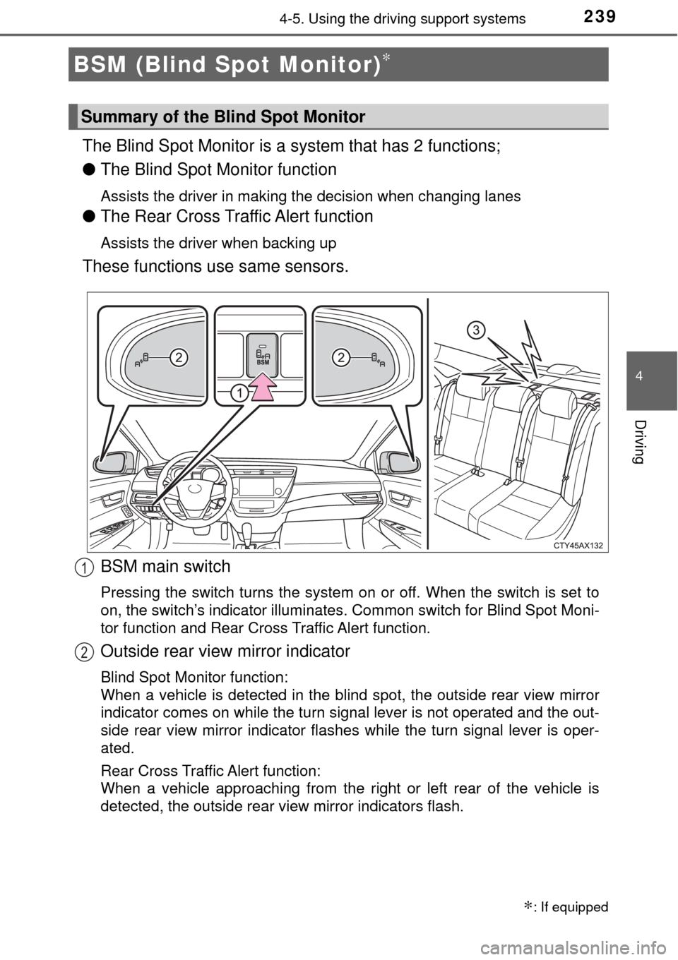
The Blind Spot Monitor is a system that has 2 functions;
● The Blind Spot Monitor function
Assists the driver in making the decision when changing lanes
●The Rear Cross Traffic Alert function
Assists the driver when backing up
These functions use same sensors.
BSM (Blind Spot Monitor)∗
∗: If equipped
Summary of the Blind Spot Monitor
BSM main switch
Pressing the switch turns the system on or off. When the switch is set to
on, the switch’s indicator illuminates. Common switch for Blind Spot Moni-
tor function and Rear Cross Traffic Alert function.
Outside rear view mirror indicator
Blind Spot Monitor function:
When a vehicle is detected in the bli nd spot, the outside rear view mirror
indicator comes on while the turn signal lever is not operated and the out-
side rear view mirror indicator flashes while the turn signal lever is oper-
ated.
Rear Cross Traffic Alert function:
When a vehicle approaching from the right or left rear of the vehicle is
detected, the outside rear view mirror indicators flash.
1
2
Page 240 of 492

2404-5. Using the driving support systems
■The outside rear view mirror indicators visibility
When under strong sunlight, the outside r ear view mirror indicator may be dif-
ficult to see.
■ Rear Cross Traffic Alert buzzer hearing
Rear Cross Traffic Alert function may be difficult to hear over loud noises
such as high audio volume.
■ When there is a malfunction in the Blind Spot Monitor system
If a system malfunction is detected due to any of the following reasons,\
warn-
ing messages will be displayed:
● There is a malfunction with the sensors
● The sensors have become dirty
Clean the sensor and its surrounding area on the bumper.
● The outside temperature is extremely high or low
● The sensor voltage has become abnormal
If a message continues to be displayed, have the vehicle inspected by your
Toyota dealer.
■ Certification for the B lind Spot Monitor system
For vehicles sold in the U.S.A.
FCC ID: OAYSRR2A
This device complies with part 15 of the FCC Rules. Operation is subject to
the following two conditions:
(1)This device may not cause harmful interference, and
(2)this device must accept any interference received, including interference that may cause undesired operation.
FCC WARNING
Changes or modifications not expressly approved by the party responsible for
compliance could void the user’s authority to operate the equipment.
For vehicles sold in Canada
Applicable law : Canada 310
This device complies with Industry Canada licence-exempt RSS standard(s).
Operation is subject to the following two conditions: (1) this device may not
cause interference, and (2) this device must accept any interference, includ-
ing interference that may cause undesired operation of the device.
Frequency bands : 24.05 - 24.25GHz
Output power : less than 20 milliwatts
Rear Cross Traffic Alert buzzer (Rear Cross Traffic Alert function
only)
When a vehicle approaching from the right or left rear of the vehicle is
detected, a buzzer sounds from behind the rear seat.
3