sensor TOYOTA AVALON 2022 Owner's Manual
[x] Cancel search | Manufacturer: TOYOTA, Model Year: 2022, Model line: AVALON, Model: TOYOTA AVALON 2022Pages: 572, PDF Size: 9.42 MB
Page 264 of 572
2644-5. Using the driving support systems
WARNING
■Before using dynamic radar cruise control with full-speed range
● Driving safely is the sole responsibility of the driver. Do not rely solely on
the system, and drive safely by always paying careful attention to your sur-
roundings.
● The dynamic radar cruise control with full-speed range provides driving
assistance to reduce the driver's burden. However, there are li mitations to
the assistance provided.
Read the following conditions carefully. Do not overly rely on this system
and always drive carefully.
• When the sensor may not be correctly detecting the vehicle ahe ad:
P. 277
• Conditions under which the vehicle-to-vehicle distance control mode
may not function correctly: P. 278
● Set the speed appropriately depending on the speed limit, traffic flow, road
conditions, weather conditions, etc. The driver is responsible for checking
the set speed.
● Even when the system is functioning normally, the condition of the preced-
ing vehicle as detected by the system may differ from the condition
observed by the driver. Therefore, the driver must always remain alert,
assess the danger of each situation and drive safely. Relying s olely on this
system or assuming the system ensures safety while driving can lead to
an accident, resulting in death or serious injury.
● Switch the dynamic radar cruise control with full-speed range s etting to off,
using the cruise control main switch when not in use.
Page 275 of 572
2754-5. Using the driving support systems
4
Driving
■Dynamic radar cruise control wi th full-speed range can be set when
● The shift lever is in D.
● The desired set speed can be set when the vehicle speed is approximately
20 mph (30 km/h) or more.
(However, when the vehicle speed is set while driving at below approxi-
mately 20 mph [30 km/h], the set speed will be set to approximately 20 mph
[30 km/h].)
■ Accelerating after setting the vehicle speed
The vehicle can accelerate by operating the accelerator pedal. After acceler-
ating, the set speed resumes. However, during vehicle-to-vehicl e distance
control mode, the vehicle speed may decrease below the set spee d in order
to maintain the distance to the preceding vehicle.
■ When the vehicle stops while follow-up cruising
●Pressing the “+ RES” switch while the vehicle ahead stops will resume fol-
low-up cruising if the vehicle ahead starts off within approxim ately 3 sec-
onds after the switch is pressed.
● If the vehicle ahead starts off within 3 seconds after your vehicle stops, fol-
low-up cruising will be resumed.
■ Automatic cancelation of vehicle-to-vehicle distance control mo de
Vehicle-to-vehicle distance control mode is automatically cance led in the fol-
lowing situations.
● VSC is activated.
● TRAC is activated for a period of time.
● When the VSC or TRAC system is turned off.
● The sensor cannot detect correctly because it is covered in some way.
● When the brake control or output restriction control of a driving support sys-
tem operates. (For example: Pre -Collision System, Drive-Start Control)
● The parking brake is operated.
● The vehicle is stopped by system control on a steep incline.
● The following are detected when the vehicle has been stopped by system
control:
• The driver is not wearing a seat belt.
• The driver’s door is opened.
• The vehicle has been stopped for about 3 minutes
If vehicle-to-vehicle distance control mode is automatically ca nceled for any
reasons other than the above, there may be a malfunction in the system.
Contact your Toyota dealer.
Page 277 of 572
2774-5. Using the driving support systems
4
Driving
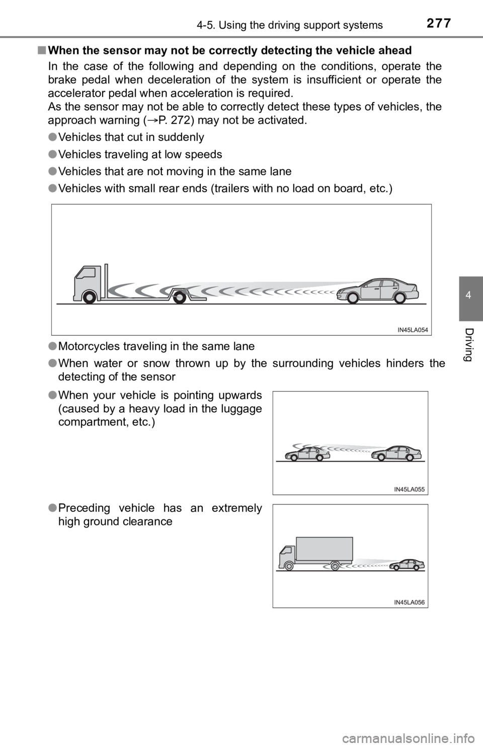
■When the sensor may not be correctly detect ing the vehicle ahead
In the case of the following and depending on the conditions, o perate the
brake pedal when deceleration of the system is insufficient or operate the
accelerator pedal when acceleration is required.
As the sensor may not be able to correctly detect these types o f vehicles, the
approach warning ( P. 272) may not be activated.
● Vehicles that cut in suddenly
● Vehicles traveling at low speeds
● Vehicles that are not moving in the same lane
● Vehicles with small rear ends (trailers with no load on board, etc.)
● Motorcycles traveling in the same lane
● When water or snow thrown up by the surrounding vehicles hinders the
detecting of the sensor
●When your vehicle is pointing upwards
(caused by a heavy load in the luggage
compartment, etc.)
● Preceding vehicle has an extremely
high ground clearance
Page 278 of 572
2784-5. Using the driving support systems
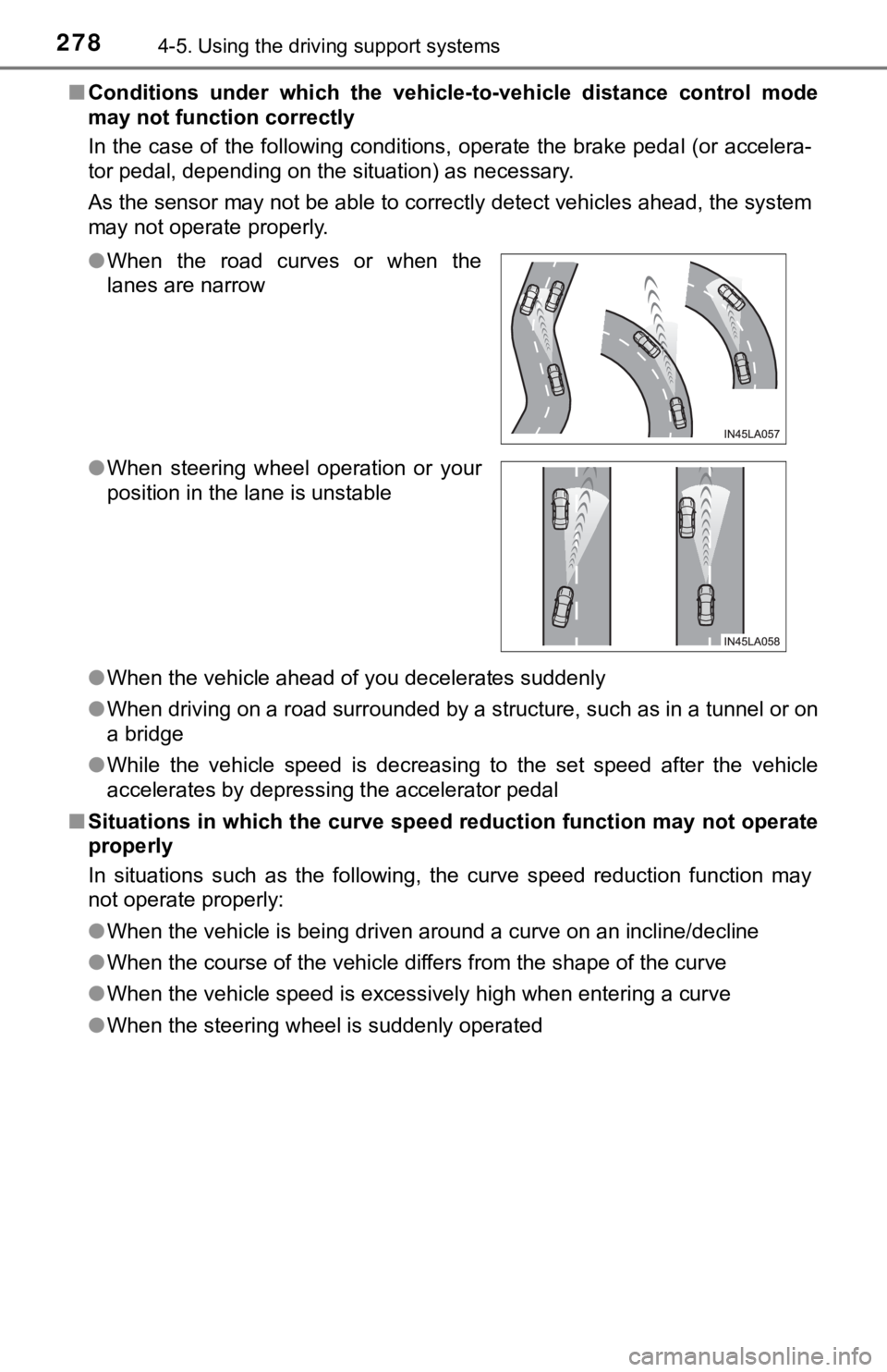
■Conditions under which the vehic le-to-vehicle distance control mode
may not function correctly
In the case of the following conditions, operate the brake peda l (or accelera-
tor pedal, depending on the situation) as necessary.
As the sensor may not be able to correctly detect vehicles ahead, the system
may not operate properly.
● When the vehicle ahead of you decelerates suddenly
● When driving on a road surrounded by a structure, such as in a tunnel or on
a bridge
● While the vehicle speed is decreasing to the set speed after th e vehicle
accelerates by depressing the accelerator pedal
■ Situations in which the curve sp eed reduction function may not operate
properly
In situations such as the following, the curve speed reduction function may
not operate properly:
● When the vehicle is being driven around a curve on an incline/d ecline
● When the course of the vehicle differs from the shape of the cu rve
● When the vehicle speed is excessively high when entering a curv e
● When the steering wheel is suddenly operated
●
When the road curves or when the
lanes are narrow
● When steering wheel operation or your
position in the lane is unstable
Page 279 of 572
2794-5. Using the driving support systems
4
Driving
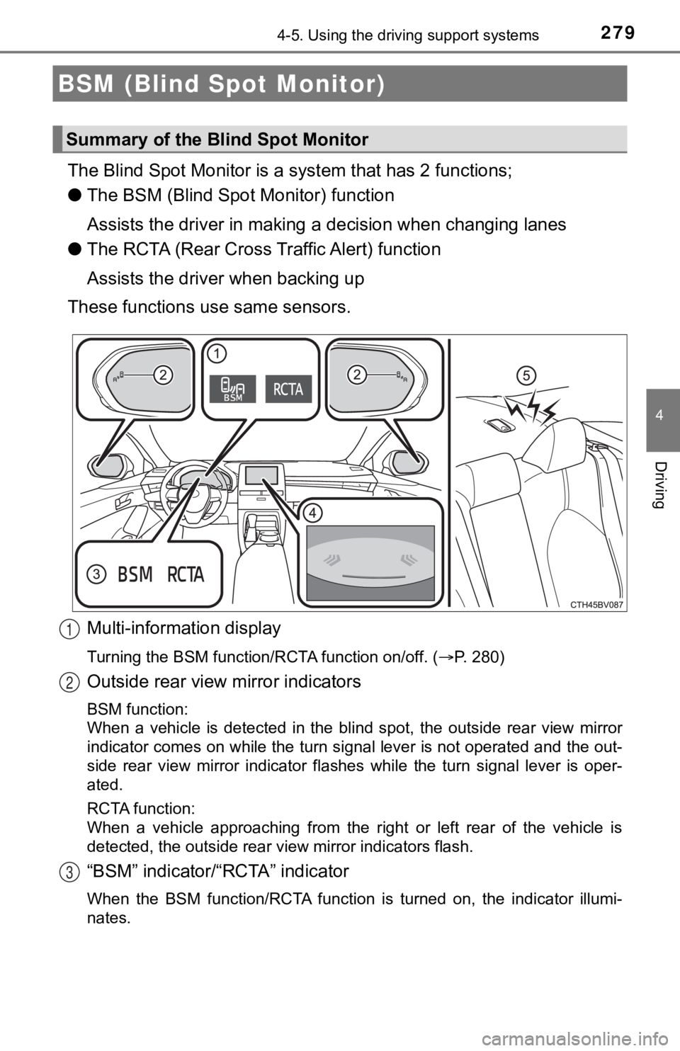
The Blind Spot Monitor is a system that has 2 functions;
● The BSM (Blind Spot Monitor) function
Assists the driver in making a decision when changing lanes
● The RCTA (Rear Cross T raffic Alert) function
Assists the driver when backing up
These functions use same sensors.
Multi-information display
Turning the BSM function/RCTA function on/off. ( P. 280)
Outside rear view mirror indicators
BSM function:
When a vehicle is detected in the blind spot, the outside rear view mirror
indicator comes on while the turn signal lever is not operated and the out-
side rear view mirror indicator flashes while the turn signal l ever is oper-
ated.
RCTA function:
When a vehicle approaching from the right or left rear of the v ehicle is
detected, the outside rear view mirror indicators flash.
“BSM” indicator/“RCTA” indicator
When the BSM function/RCTA function is turned on, the indicator illumi-
nates.
BSM (Blind Spot Monitor)
Summary of the Blind Spot Monitor
1
2
3
Page 280 of 572
2804-5. Using the driving support systems
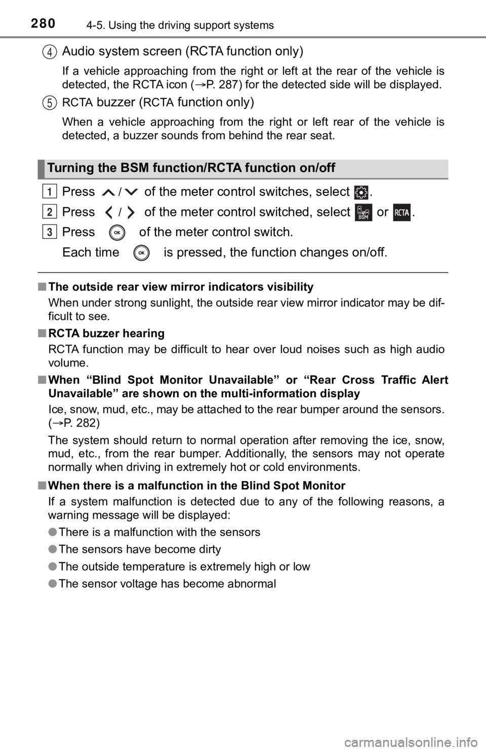
Audio system screen (RCTA function only)
If a vehicle approaching from the right or left at the rear of the vehicle is
detected, the RCTA icon ( P. 287) for the detected side will be displayed.
RCTA
buzzer (RCTA function only)
When a vehicle approaching from the right or left rear of the v ehicle is
detected, a buzzer sounds from behind the rear seat.
Press / of the meter control switches, select .
Press
/ of the meter control sw itched, select or .
Press of the meter control switch.
Each time is pressed, t he function changes on/off.
■The outside rear view mirror indicators visibility
When under strong sunlight, the outside rear view mirror indica tor may be dif-
ficult to see.
■ RCTA buzzer hearing
RCTA function may be difficult to hear over loud noises such as high audio
volume.
■ When “Blind Spot Monitor Unava ilable” or “Rear Cross Traffic Alert
Unavailable” are shown on the multi-information display
Ice, snow, mud, etc., may be attached to the rear bumper around the sensors.
( P. 282)
The system should return to normal operation after removing the ice, snow,
mud, etc., from the rear bumper. Additionally, the sensors may not operate
normally when driving in extremely hot or cold environments.
■ When there is a malfunction in the Blind Spot Monitor
If a system malfunction is detected due to any of the following reasons, a
warning message will be displayed:
● There is a malfunction with the sensors
● The sensors have become dirty
● The outside temperature is extremely high or low
● The sensor voltage has become abnormal
Turning the BSM function/RCTA function on/off
4
5
1
2
3
Page 282 of 572
2824-5. Using the driving support systems
WARNING
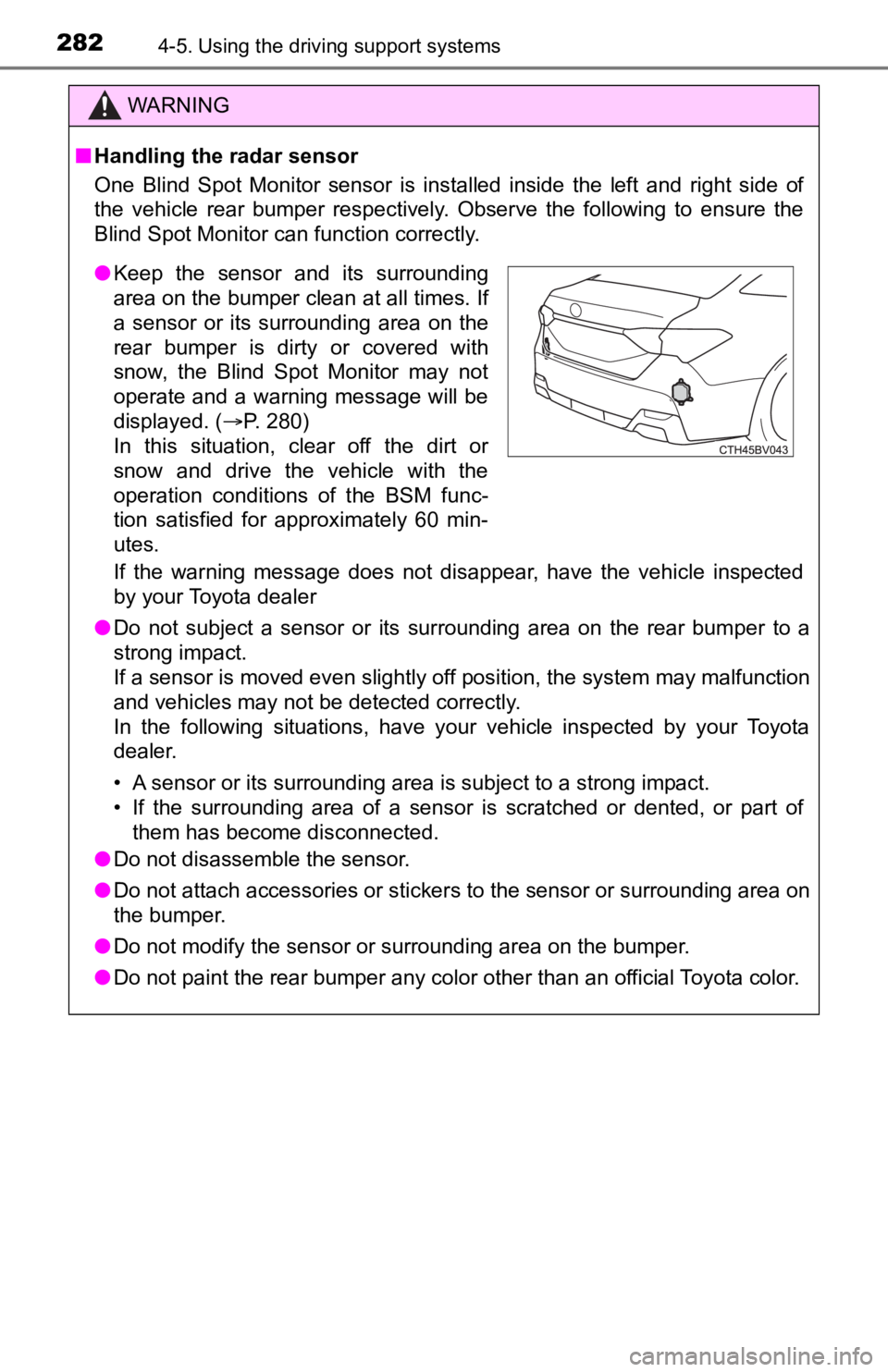
■Handling the radar sensor
One Blind Spot Monitor sensor is installed inside the left and right side of
the vehicle rear bumper respectively. Observe the following to ensure the
Blind Spot Monitor can function correctly.
If the warning message does not disappear, have the vehicle inspected
by your Toyota dealer
● Do not subject a sensor or its surrounding area on the rear bumper to a
strong impact.
If a sensor is moved even slightly off position, the system may malfunction
and vehicles may not be detected correctly.
In the following situations, have your vehicle inspected by your Toyota
dealer.
• A sensor or its surrounding area is subject to a strong impact .
• If the surrounding area of a sensor is scratched or dented, or part of them has become disconnected.
● Do not disassemble the sensor.
● Do not attach accessories or stickers to the sensor or surrounding area on
the bumper.
● Do not modify the sensor or surrounding area on the bumper.
● Do not paint the rear bumper any color other than an official Toyota color.
●Keep the sensor and its surrounding
area on the bumper clean at all times. If
a sensor or its surrounding area on the
rear bumper is dirty or covered with
snow, the Blind Spot Monitor may not
operate and a warning message will be
displayed. ( P. 280)
In this situation, clear off the dirt or
snow and drive the vehicle with the
operation conditions of the BSM func-
tion satisfied for approximately 60 min-
utes.
Page 283 of 572
2834-5. Using the driving support systems
4
Driving
The BSM function uses radar sensors to detect vehicles that are trav-
eling in an adjacent lane in the area that is usually not reflected in the
outside rear view mirror (the blind spot), and advises the driv er of the
vehicles existence vi a the outside rear vie w mirror indicator.
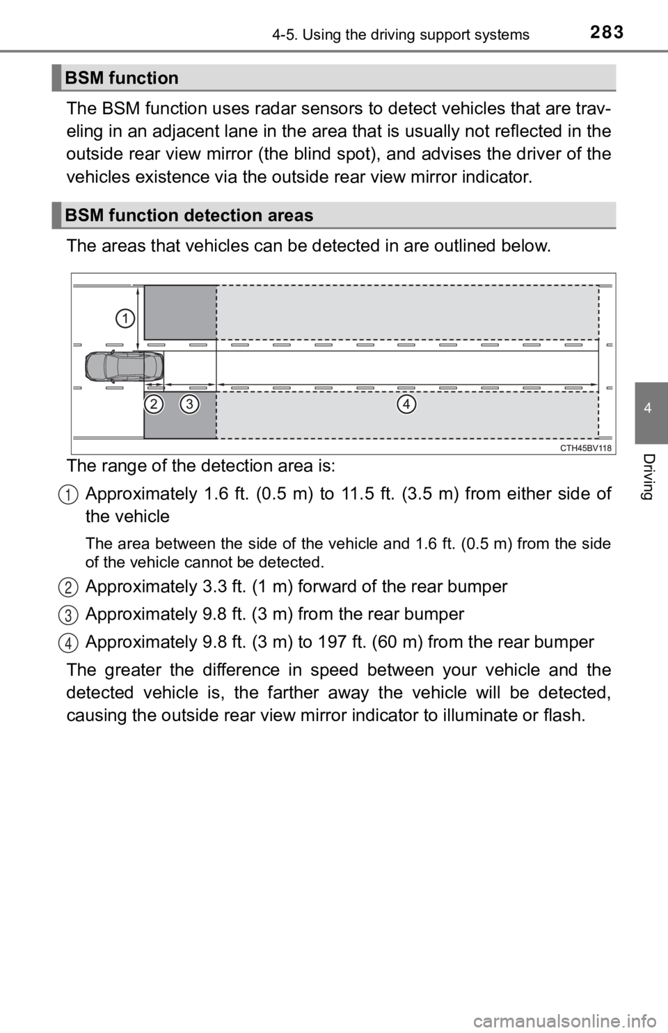
The areas that vehicles can be detected in are outlined below.
The range of the detection area is: Approximately 1.6 ft. (0.5 m) to 11.5 ft. (3.5 m) from either s ide of
the vehicle
The area between the side of the vehicle and 1.6 ft. (0.5 m) from the side
of the vehicle cannot be detected.
Approximately 3.3 ft. (1 m) f orward of the rear bumper
Approximately 9.8 ft. (3 m) from the rear bumper
Approximately 9.8 ft. (3 m) to 19 7 ft. (60 m) from the rear bumper
The greater the difference in speed between your vehicle and th e
detected vehicle is, the farther away the vehicle will be detec ted,
causing the outsi de rear view mirror indicator to illuminate or flash.
BSM function
BSM function detection areas
1
2
3
4
Page 285 of 572
2854-5. Using the driving support systems
4
Driving
■Conditions under which the BSM function will not detect a vehic le
The BSM function is not designed to detect the following types of vehicles
and/or objects:
● Small motorcycles, bicycles, pedestrians, etc.
*
●Vehicles traveling in the opposite direction
● Guardrails, walls, signs, parked vehicles and similar stationar y objects
*
●Following vehicles that are in the same lane*
●Vehicles driving 2 lanes across from your vehicle*
●Vehicles which are being overtaken rapidly by your vehicle
*: Depending on the conditions, detection of a vehicle and/or obj ect may
occur.
■ Conditions under which the BSM function may not function correc tly
● The BSM function may not detect vehicles correctly in the following condi-
tions:
• When the sensor is misaligned due to a strong impact to the se nsor or its
surrounding area
• During bad weather such as heavy rain, fog, snow, etc.
• When mud, snow, ice, a sticker, etc., is covering the sensor o r surround-
ing area on the rear bumper
• When driving on a road surface that is wet due to rain, standi ng water,
snow, etc.
• When there is a significant difference in speed between your v ehicle and
the vehicle that enters the detection area
• When a vehicle is in the detection area from a stop and remains in the detection area as your vehicle accelerates
• When driving up or down consecutive steep inclines, such as hills, a dip
in the road, etc.
• When driving on roads with sharp bends, consecutive curves, or uneven
surfaces
• When multiple vehicles approach with only a small gap between each vehicle
• When vehicle lanes are wide, and the vehicle in the next lane is too far
away from your vehicle
• When the vehicle that enters the detection area is traveling a t about the
same speed as your vehicle
• When there is a significant difference in height between your vehicle and
the vehicle that enters the detection area
• Immediately after the BSM function is turned on
Page 286 of 572
2864-5. Using the driving support systems
●Instances of the BSM function unnecessarily detecting a vehicle and/or
object may increase under the following conditions:
• When the sensor is misaligned due to a strong impact to the se nsor or its
surrounding area
• When there is only a short distance between your vehicle and a guardrail,
wall, etc.
• When there is only a short distance between your vehicle and a following
vehicle
• When vehicle lanes are narrow and a vehicle driving 2 lanes ac ross from
your vehicle enters the detection area
• When driving on roads with sharp bends, consecutive curves, or uneven
surfaces
• When items such as a bicycle carrier are installed on the rear of the vehi-
cle
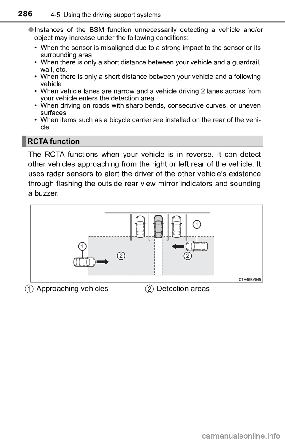
The RCTA functions when your vehicle is in reverse. It can dete ct
other vehicles approaching from the right or left rear of the v ehicle. It
uses radar sensors to alert the driver of the other vehicle’s existence
through flashing the outside rear view mirror indicators and so unding
a buzzer.
RCTA function
Approaching vehicles Detection areas12