center TOYOTA AVENSIS 2003 Service Repair Manual
[x] Cancel search | Manufacturer: TOYOTA, Model Year: 2003, Model line: AVENSIS, Model: TOYOTA AVENSIS 2003Pages: 2234, PDF Size: 56.95 MB
Page 1842 of 2234
B66534
B66535
Clip
B66527
Clip
±
EXTERIOR/INTERIOR TRIMROOF HEADLINING ASSY(WAGON MODELS)
76±55
AVENSIS REPAIR MANUAL (RM1018E)
7.REMOVE FRONT DOOR OPENING TRIM WEATHERSTRIP RH
8.REMOVE FRONT DOOR OPENING TRIM WEATHERSTRIP LH
9.REMOVE REAR DOOR OPENING TRIM WEATHERSTRIP RH
10.REMOVE REAR DOOR OPENING TRIM WEATHERSTRIP LH
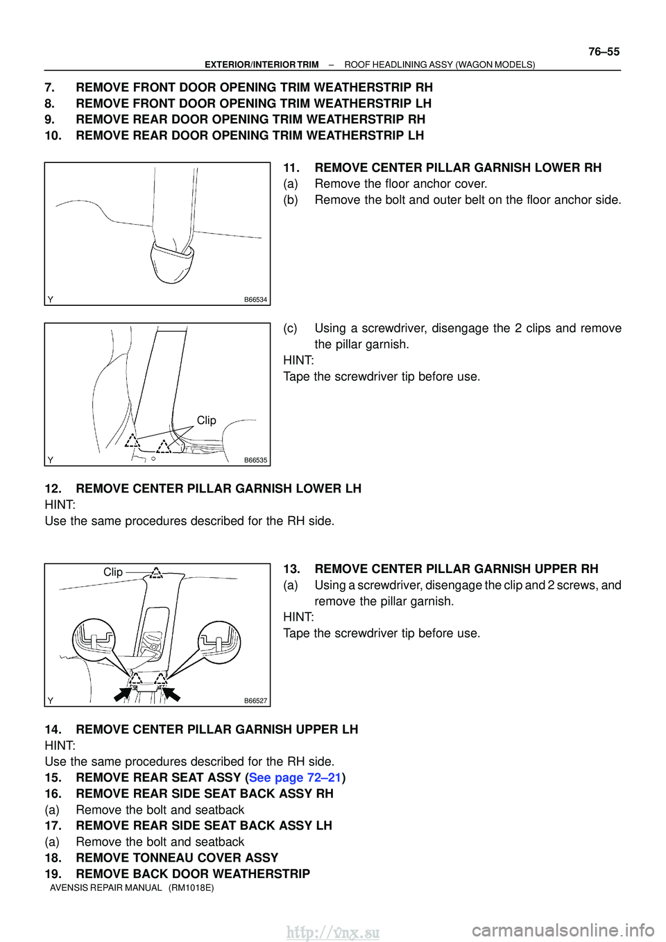
11.REMOVE CENTER PILLAR GARNISH LOWER RH
(a)Remove the floor anchor cover.
(b)Remove the bolt and outer belt on the floor anchor side.
(c)Using a screwdriver, disengage the 2 clips and removethe pillar garnish.
HINT:
Tape the screwdriver tip before use.
12.REMOVE CENTER PILLAR GARNISH LOWER LH
HINT:
Use the same procedures described for the RH side. 13.REMOVE CENTER PILLAR GARNISH UPPER RH
(a)Using a screwdriver, disengage the clip and 2 screws, andremove the pillar garnish.
HINT:
Tape the screwdriver tip before use.
14.REMOVE CENTER PILLAR GARNISH UPPER LH
HINT:
Use the same procedures described for the RH side.
15.REMOVE REAR SEAT ASSY (See page 72±21)
16. REMOVE REAR SIDE SEAT BACK ASSY RH
(a) Remove the bolt and seatback
17. REMOVE REAR SIDE SEAT BACK ASSY LH
(a) Remove the bolt and seatback
18. REMOVE TONNEAU COVER ASSY
19. REMOVE BACK DOOR WEATHERSTRIP
http://vnx.su
Page 1854 of 2234
[N]
[O] [P]
[Q] [R]
[S]
[T]
[U]
6 AVENSIS (EWD526E)
B HOW TO USE THIS MANUAL
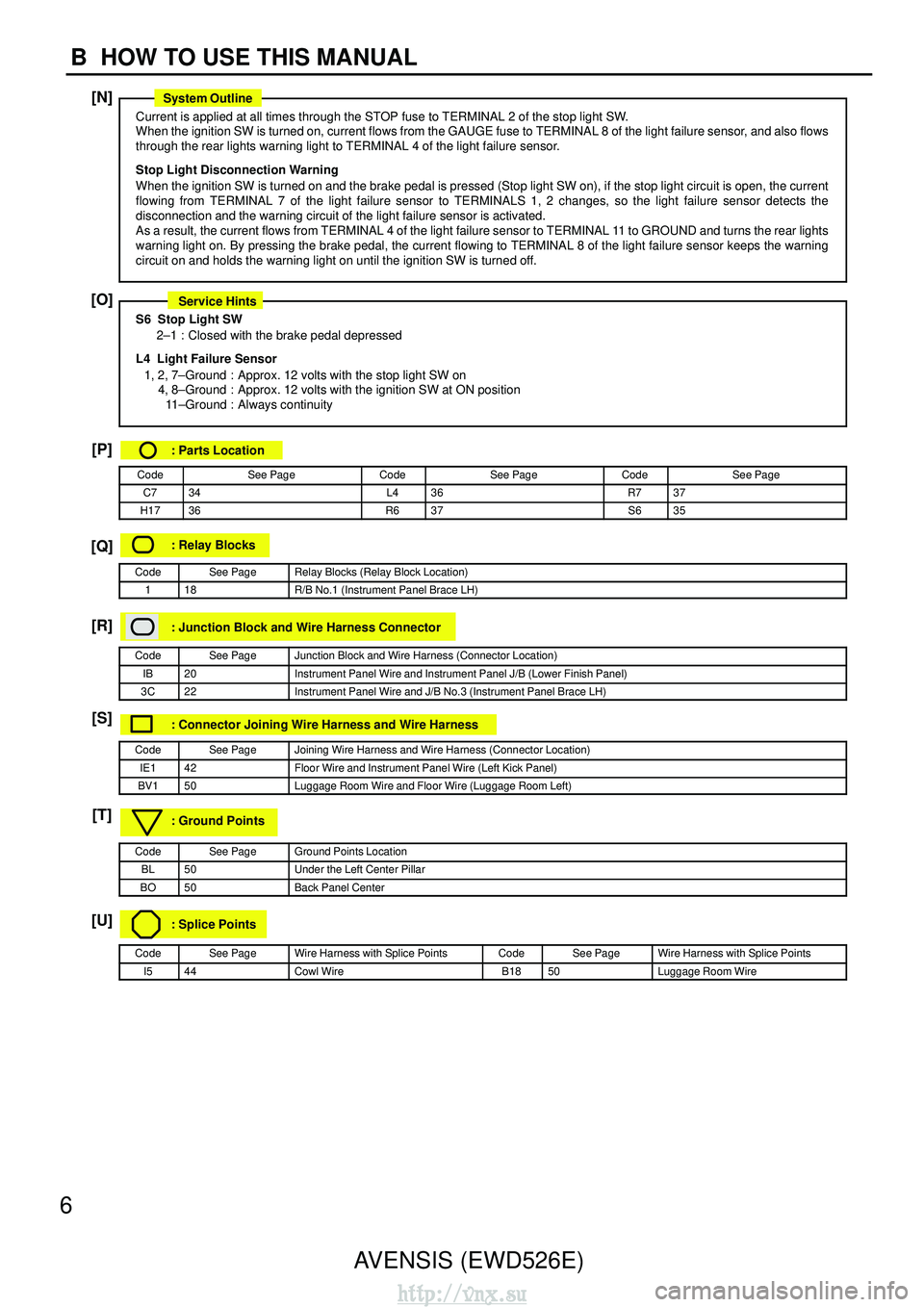
Current is applied at all times through the STOP fuse to TERMINAL 2 of the stop light SW.
When the ignition SW is turned on, current flows from the GAUGE fuse to TERM\
INAL 8 of the light failure sensor, and also flows
through the rear lights warning light to TERMINAL 4 of the light failure sensor\
.
Stop Light Disconnection Warning
When the ignition SW is turned on and the brake pedal is pressed (Stop ligh\
t SW on), if the stop light circuit is open, the cur
rent
flowing from TERMINAL 7 of the light failure sensor to TERMINALS 1, 2 changes, \
so the light failure sensor detects the
disconnection and the warning circuit of the light failure sensor is activated.
As a result, the current flows from TERMINAL 4 of the light failure sens\
or to TERMINAL 11 to GROUND and turns the rear lights
warning light on. By pressing the brake pedal, the current flowing to TERMINAL \
8 of the light failure sensor keeps the warning
circuit on and holds the warning light on until the ignition SW is turne\
d off.
S6 Stop Light SW
2–1 : Closed with the brake pedal depressed
L4 Light Failure Sensor 1, 2, 7–Ground : Approx. 12 volts with the stop light SW on 4, 8–Ground : Approx. 12 volts with the ignition SW at ON position11 –Ground : Always continuity
: Parts Location
CodeSee PageCodeSee PageCodeSee Page
C734L436R737
H1736R637S635
: Relay Blocks
CodeSee PageRelay Blocks (Relay Block Location)
118R/B No.1 (Instrument Panel Brace LH)
: Junction Block and Wire Harness Connector
CodeSee PageJunction Block and Wire Harness (Connector Location)
IB20Instrument Panel Wire and Instrument Panel J/B (Lower Finish Panel)
3C22Instrument Panel Wire and J/B No.3 (Instrument Panel Brace LH)
: Connector Joining Wire Harness and Wire Harness
CodeSee PageJoining Wire Harness and Wire Harness (Connector Location)
IE142Floor Wire and Instrument Panel Wire (Left Kick Panel)
BV150Luggage Room Wire and Floor Wire (Luggage Room Left)
: Ground Points
CodeSee PageGround Points Location
BL50Under the Left Center Pillar
BO50Back Panel Center
: Splice Points
CodeSee PageWire Harness with Splice PointsCodeSee PageWire Harness with Splice Points
I544Cowl WireB1850Luggage Room Wire
System Outline
Service Hints
http://vnx.su
Page 1855 of 2234
7
B
[N]
: Explains the system outline.
[O] : Indicates values or explains the function for reference during troublesh\
ooting.
[P] : Indicates the reference page showing the position")
AVENSIS (EWD526E)7
B
[N]
: Explains the system outline.
[O] : Indicates values or explains the function for reference during troublesh\
ooting.
[P] : Indicates the reference page showing the position on the vehicle of the \
parts in the system circuit.
Example : Part ”L4” (Light Failure Sensor) is on page 36 of the manual.
∗ The letter in the code is from the first letter of the part, and the num\
ber indicates its order in parts
starting with that letter.
Example : L 4
Parts is 4th in order
Light Failure Sensor
[Q] : Indicates the reference page showing the position on the vehicle of Rela\
y Block Connectors in the system circuit.
Example : Connector ”1” is described on page 18 of this manual and is installed on the left sid\
e of the instrument
panel.
[R] : Indicates the reference page showing the position on the vehicle of J/B and Wire \
Harness in the system circuit.
Example : Connector ”3C” connects the Instrument Panel Wire and J/B No.3. It is described on pag\
e 22 of this
manual, and is installed on the instrument panel left side.
[S] : Indicates the reference page describing the wiring harness and wiring harness con\
nector (the female wiring
harness is shown first, followed by the male wiring harness).
Example : Connector ”IE1” connects the floor wire (female) and Instrument panel wire (male). \
It is described on
page 42 of this manual, and is installed on the left side kick panel.
[T] : Indicates the reference page showing the position of the ground points o\
n the vehicle.
Example : Ground point ”BO” is described on page 50 of this manual and is installed on the back pan\
el center.
[U] : Indicates the reference page showing the position of the splice points o\
n the vehicle.
Example : Splice point ”I5” is on the Cowl Wire Harness and is described on page 44 of this manual.\
http://vnx.su
Page 1869 of 2234
AVENSIS (EWD526E)21
F
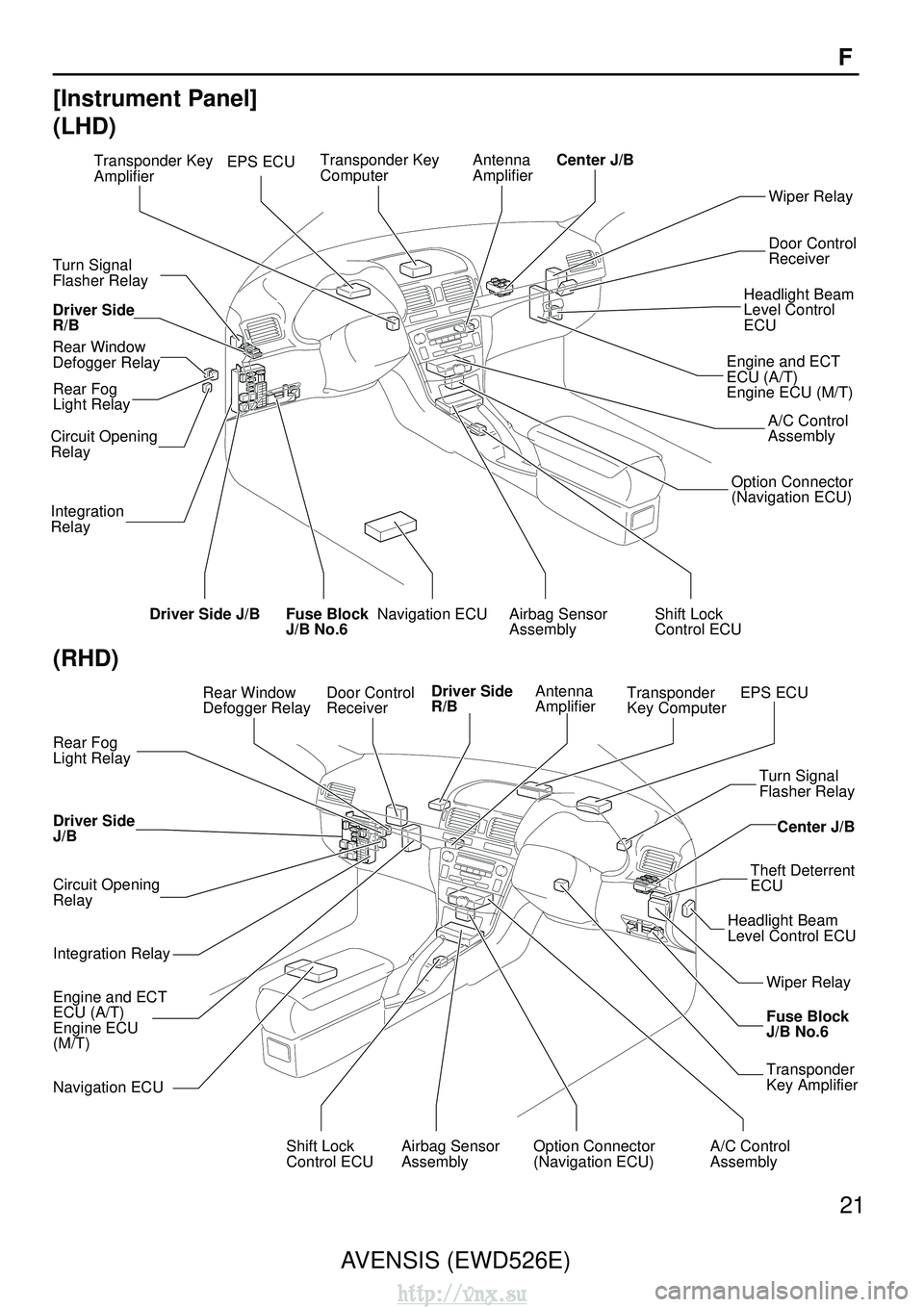
[Instrument Panel]
(LHD)
Fuse Block
J/B No.6
Wiper Relay
Door Control
Receiver
Headlight Beam
Level Control
ECU
A/C Control
Assembly
Option Connector
(Navigation ECU)
Engine and ECT
ECU (A/T)
Engine ECU (M/T)
Navigation ECUShift Lock
Control ECUAirbag Sensor
Assembly
Driver Side
R/B
Rear Window
Defogger Relay
Turn Signal
Flasher Relay
Rear Fog
Light Relay
Circuit Opening
Relay
Integration
Relay
Driver Side J/B EPS ECU
Transponder Key
AmplifierTransponder Key
ComputerAntenna
AmplifierCenter J/B
(RHD)
Shift Lock
Control ECU
Center J/B
Turn Signal
Flasher Relay
Theft Deterrent
ECU
Headlight Beam
Level Control ECU
Wiper Relay
Fuse Block
J/B No.6
Transponder
Key Amplifier
Airbag Sensor
AssemblyOption Connector
(Navigation ECU)
Driver Side
J/B
Integration Relay
Engine and ECT
ECU (A/T)
Engine ECU
(M/T)
Navigation ECU
Circuit Opening
Relay
Rear Fog
Light Relay
A/C Control
Assembly
Door Control
Receiver
Driver Side
R/BAntenna
AmplifierTransponder
Key ComputerEPS ECURear Window
Defogger Relay
http://vnx.su
Page 1879 of 2234
1235
67891011
101112
1213
1011
1011
12134
5
10 4321
9876
87
9
65 1
423 12345
6789
321 456789 43 21
56789
12 345
6789
123456
789
12 3
456789 12345
10
6789
123 45
6789
1011
10 111213
12 34
56789
10
(from Instrument Panel Wire)
(from Instrument Panel Wire)
(from Instrument Panel Wire)
1112
10 1112 13
(from Instrument Panel Wire)
(from Instrument Panel Wire)
(from Instrument Panel Wire)
CF
CB
CD
CC
CA
CE
34
AVENSIS (EWD526E)
F RELAY LOCATIONS
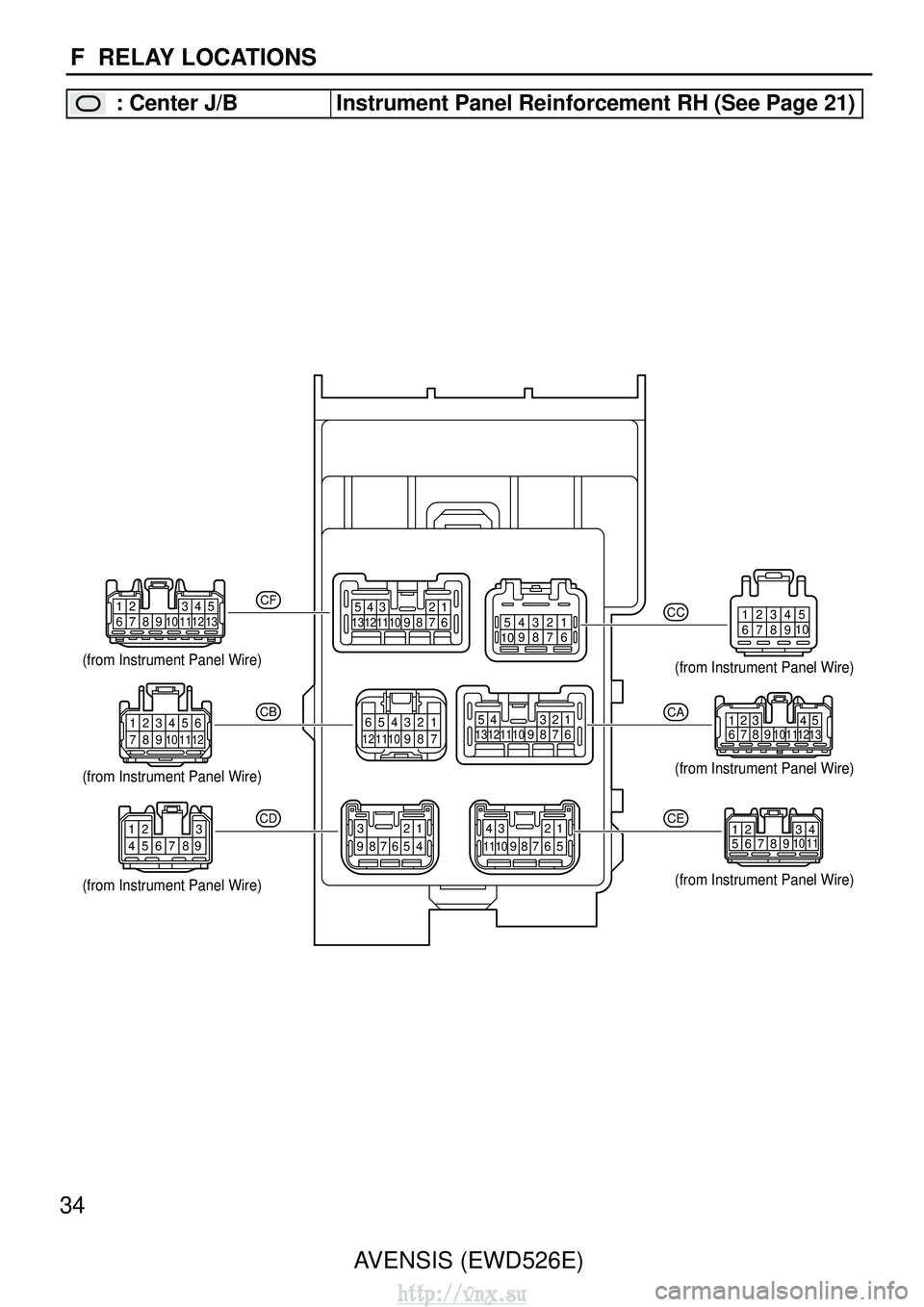
: Center J/BInstrument Panel Reinforcement RH (See Page 21)
http://vnx.su
Page 2143 of 2234

AVENSIS (EWD526E)
580 M OVERALL ELECTRICAL WIRING DIAGRAM
1 23
4
1 AVENSIS (
C ont. ne xt pa ge )
B–G
4B
1
1 4D
1 1
AM1 IG1 ACC
3
2 13
5
10A GAUGE1
IJLeft Kick Panel
140A ALT
120A ALT
(
1AZ–FSE, 1AZ–FE )
100A ALT (
1ZZ–FE, 3ZZ–FE )
40A MAIN W–B
W–B
G–Y
B–G
(
∗ 1 )
G–R B–G
FL MAIN
3. 0WBattery IG1
Relay
1 2
3 2
3
W
1
2
1ED1
(
∗ 1 )
B–G
( ∗ 1 )
B–L B–L
(
∗ 2 )
(∗ 2 )
(
∗ 2 ) (
∗ 1 )
I13
DH
1D H
5DN 1
1 DA
9
6
W–R
25A AM1
7. 5A ECU–B 2
25 E
W–L
M ultiplex C ommunication System
(
LHD )
Power Source
∗ 1 : Gasoline
∗ 2 : 1CD–FTV
Ignition SW
4A
1
1A
1
3
30A DCC
1
1
2
B–W
B
B
B–G( ∗ 1 )
(
∗ 2 )
( ∗ 2 )
4IE4
B–W
B–W
22IG
23 B Integration Relay
I14
(
A )
1
25A DOOR
B
21 ACC
7. 5A RAD NO. 1
DH
3
2
G
G
CD
3
10 CC
W–R
W–R
DB
16
W–R
CF
9
(
∗ 4 )
DK
6W–B
6 6
W–R 7. 5A DOME
1 2
1
2
1 2
5
3
TAIL Relay
15 INTB
7. 5A PANEL
DB
19 DJ
9
G–W
∗ 3 : w/ Daytime Running Light
(
∗ 3 )
(∗ 3 )
DB
4
GR
DB
7R–W
B A
W–R
(
∗ 4 )
W–L (
∗ 3 )
∗
4 : w/ Wireless Door Lock
R–W
W–RW–B GR
EF
D C
13
TRLY
IO Instrument Panel
Reinforcement RH
IL
Behind the
Combination Meter W–B
W–B
(∗ 1 )
(
∗ 2 )
AVENSIS (EWD526E)
581M
5
67
8
1 AVENSIS (
C ont' d )
(
C ont. ne xt pa ge )
DIM
M ultiplex C ommunication System (
LHD )
R–Y
Headlight Cleaner
SW< 28–4> < 30–4> H–LP Relay
22
2 1 5
3
22 W–L
R–Y
W–L
14 A
R–L
Headlight Beam Level
Control ECU< 24–3>
15 IC2 2A
R–Y
HRLY
R–Y
EA
DBJunction
ConnectorJ 3 (
A )
, J 4 (
B )
12 T
Taillight System
< 14–1> W–R
CA
CA
CB
CA
R–Y R–Y
( ∗ 6 )
(
∗ 3 ∗5 )
Junction
ConnectorJ 6 (
A )
, J 7 (
B )
D 6Door Control
Receiver
IC2
7
(
∗ 4 ) G–Y
L–W
( ∗ 4 ) W–B
IC2
16
2
3
1
(∗ 4 )
(
∗ 4 )
16 A A
7
PRG RDA
L–W
G–Y
14 TOUT
20P/W
Moon Roof System
< 32–2>
Power Window System
< 33–3>
DB
12 DA
5
ECT and A/T Indicator System
< 10–2> < 12–2>
SNOW
8
DA
14
W–G
IC3
1 21 A
W–G
OBD2
15 A
LG
FRLY
Turn Signal Flasher Relay
< 15–3>
9A
L–R
BKL
IC2
12
Illumination System
< 19–3>
DJ
6
DIM
Relay
22
1 2 5
3
22
6IB1
W–R
W–R
R–L
R–B
R–Y
(
∗ 3 )
( ∗ 3 )
(∗ 8 )
(
∗ 3 ) (
∗ 3 ) (
∗ 3 )
( ∗ 3 )
(
∗ 3 ) (
∗ 3 )
(
∗ 3 )
(
∗ 3 )
(
∗ 3 )
(
∗ 3 )
Integration RelayI14 (
A )
C
D
E F
R–W
GR
W–B
W–R
W–R
(
∗ 4 )
W–L (
∗ 3 )
A
B W–R
B A
R–B
( ∗ 3 )
(
∗ 3 )
GR
D
F
C
E W–B
R–W
W–R
L–R
Airbag Sensor Assembly
< 22–11>
W–B
G
∗
6 : ∗ 3 w/ HID
∗ 5 : w/ Headlight Cleaner
∗
4 : w/ Wireless Door Lock
(
∗ 3 )
W–R
R–Y
DB
(∗ 3 )
A/C Control
Assembly
<48–8><49–8>
∗
3 : w/ Daytime Running Light
∗ 8 : ∗ 3 Power Heater (
Electrical Type )
(∗ 4 )
(
∗ 4 )
DLC3
<5–19><6–15><7–14><8–15>
GROUND
PRG RDA
(
∗ 3 )
(
∗ 3 )
(
A/T ) W–R
5
+B
(
∗ 4 )
AVENSIS (EWD526E)
582 M OVERALL ELECTRICAL WIRING DIAGRAM
9 10 11
12
1 AVENSIS (
C ont' d )
(
C ont. ne xt pa ge )
M ultiplex C ommunication S ystem (
LHD )
OFF DA
13 A
18 H
HUHL
HT
EL
Low
Head
High
Dimmer S W
Tail
R–Y R–Y
W–B
Flash
(∗ 7 )
Light
Control SW
28
GRW–R ( ∗ 3 ) (
∗ 3 )
2
1
(
∗ 3 )
R
2 15A
H–LP LH 15A
H–LP RH
2
22
( ∗ 3 )
(∗ 3 )
( ∗ 3 )(
∗3 )
(
∗ 3 )(
∗3 )
( ∗ 3 )
(
∗ 3 ) 2
10A
H–LP
HI LH 10A
H–LP
HI RH
22
2
33 2
EC Engine Compartment Left
EB2
(
∗ 3 )
2
2 11
11 R–B
R–W
W–B
W–B
W–B
W–B W–B
W–B
R
R–B R–Y
R–L
R–L
H 6
H 5Headlight LH
(
High )
Headlight RH
(
High )
R–L
W–B
IL
Behind the
Combination Meter BA
AEAE
R–Y R–Y
R–Y
( ∗ 6 )
(
∗ 6 )
(∗ 6 )
IE1
10
(
∗ 3 )
(
∗ 3 )
(
∗ 3 )
(∗ 2 ∗3 )
(
∗ 3 )
R–Y Headlight Cleaner
Relay< 28–4>
( ∗ 6 )
Junction Connector
J 6(
A )
, J 7 (
B )3IC3
R–Y
HF
6A
R–W
9IC3
R–W
HU
BE
A
DA D
Engine Compartment Right
Headlight Control ECU LHF 7
( ∗ 7 )
(
∗ 6 )(
∗6 )
( ∗ 7 )
A A 2
1
R–B
W–B
Headlight Control ECU RH
F 9
(
∗ 7 )
(
∗ 6 )(
∗6 )
( ∗ 7 )
(
∗ 3 )
(∗ 3 )
W–B
W–B
W–B
Junction
Connector
J 2
G
W–B
F
W–B Integration Relay
I14
(
A )
R–W (
∗ 3 )
B
W–B A
C
E
D
GR
W–R R–W
( ∗ 3 )
A R–B
W–R
D B
F
C
E W–B
R–W
W–R (
∗ 3 ) ∗
7 : ∗ 3 w/o HID
∗
6 : ∗ 3 w/ HID
∗ 3 : w/ Daytime Running Light
( ∗ 4 )
(
∗ 4 )
∗
4 : w/ Wireless Door Lock
1 2
Headlight LH (
Low )F 82
1Headlight RH (
Low )F10
HF
16 13 7 8
Combination SW
C12
J 8(
A )
, J 9 (
B )Junction Connector
GR
GR
AF BHJunction ConnectorJ 3 (
A )
, J 4 (
B )
∗
1 : Gasoline
∗ 2 : 1CD–FTV
IO Instrument Panel
Reinforcement RH
(
∗ 1 ∗3 )
W–B
Engine
Compartment
Right
EA
W–B
ED
Engine
Compartment
Left W–B
AVENSIS (EWD526E)
583M
13
14 15
16
1 AVENSIS (
C ont' d )
(
C ont. ne xt pa ge )
M ultiplex C ommunication System (
LHD )
(
∗ 3 )
F W–B
W–B8CD 2 1
2
1
Integration Relay
I14
(
A )
2
4
3
Vanity Light LHV 8Vanity Light RHV 9Personal LightP 8
DK
7 6
LP
W–G
Ignition Key
Cylinder Light
I11(
A )
, I12 (
B )6B (
∗ 9 )
6A
(
∗ 10 )
2A (
∗ 10 )
2B (
∗ 9 )
DA
1
W–G W–G
W–B
W–B
W–B
W–B
BH
AFBHBH
4ID1
AF
W–R
W–R W–R
W–R
W–R
W–R
W–R
W–R W–R
A
W–R
W–B B
B
R–W
(
∗ 3 )
W–R R–W
D W–B
A
E
C
GR
W–R
20 B
2A
GR
5B
W–B
7CD
CD
6
R–W
21 B
R–W
Right Kick Panel
IP
CK
6
CA
6
W–B
Door
BEAN
I/F
14 A 22 A 11 A
1IC1 10 IC1
P
P–B P–B P
MPX1
MPX2
13 A
P
MPX+ MPX–
9A
10 B 20 B 29 A
P–B
( ∗ 12 )
CPU (
∗ 13 )
( ∗ 12 )
( ∗ 13 )A/C Control AssemblyA13 (
A )
, A15 (
B )
, A16 (
C )
MPX1 MPX2
18 B
23 A 21 A 29 A (
∗ 11 )
( ∗ 2 )
( 1AZ–FSE )
( ∗ 11 )
Engine ECU (
M/T )
Engine and ECT ECU
(
A/T )E 9(
A )
, E10 (
B )
29 B (
1AZ–FSE )
20 A (
∗ 2 )
P
W–R
A6
( ∗ 3 )
High Beam
W–B
W–B
W–B
( ∗ 4 )
(
∗ 4 ) ILL+ ILL–
W–R
Seat Belt
( ∗ 15 )
7
(
∗ 14 )
G–Y
IM1
14
(
∗ 14 )
W–B
G–Y
Under the Right
Center Pillar
BV
W–B
F19Front Passenger' s Seat Belt
Warning Light
4
R–W
(∗ 14 )
8
B10
6
(
∗ 14 )
L–R
3
1
(
∗ 15 )
Buzzer
( ∗ 14 ) (
∗ 14 )
Combination MeterC10 (
A )
, C11 (
B )12 B
R–W
PBLT
24 A
3C
L–R
7CA
R–W
( ∗ 14 )
∗13 : Automatic A/C
∗
9 : w/ Engine Immobiliser System
∗ 12 : Except Automatic A/C
∗
2 : 1CD–FTV
∗ 11 : 1AZ–FE, 1ZZ–FE, 3ZZ–FE
∗
10 : w/o Engine Immobiliser System
∗
3 : w/ Daytime Running Light
∗ 4 : w/ Wireless Door Lock
∗ 14 : Except 1AZ–FE
∗ 15 : Except 1AZ–FE, Latin America, Argentina, CIS
(
∗ 14 )
(∗ 15 )
CH
9
W–B
( ∗ 14 )
BU Under the Right
Center PillarW–B
Junction ConnectorJ10
(
A )
, J11 (
B )
C
W–B
( ∗ 3 )
IG
E PBEW B–PBEW
Buckle SW (
Front Passenger' s Side )
Occupant Detection Sensor
AVENSIS (EWD526E)
584 M OVERALL ELECTRICAL WIRING DIAGRAM
17 18 19
20
1 AVENSIS (
C ont' d )
(
C ont. ne xt pa ge )
M ultiplex C ommunication S ystem (
LHD )
Y
( ∗ 9 )
1Door Courtesy SW
Rear RHD12
W–G
1Door Courtesy SW
Rear LHD11
W–G
1Door Courtesy SW
Front RHD10
R
1Door Courtesy SW
Front LHD 9
R
IC2
4
IM1
18
14 IC2 9 IM1 DM
13
DM
12
DC
9
BD ABAB 16
RCTY
DB
13 17
DCTY
R
W–G W–G W–G
R R
R
DK
2
W–G Junction
Connector
J10
(
A )
, J11 (
B )
I16
DB
2 9
PCTY
R
11 IL1
10 IL1 2
1
AF BHAF
AF
RW –RW –R
D 8
R
11 IA1
10 IA1 2
1
RW
–RW –R
D 7
B
R–Y
(
S/D )
11 ID1
W–R
W–B
W–R
W–R432
Junction
Connector
J 6 (
A )
, J 7 (
B )
R
5IC2W–R
BH
B
1
2
W–R
B
Diode
D 3
Integration RelayI14
(
A )
A W–R
W–B
B 2
L 5Luggage
Compartment Light
(
S/D )
1J32Junction
Connector
A
A
W–R
R–Y
1A LGCY
R–Y
R–Y R–Y
A
(S/D )(
S/D)
(∗ 16 )
Instrument Panel
Reinforcement RH IO
W–B
ADA
6
DA
8 19
KSW
Y Y
1 2
Transponder Key Computer
<9–4>
Junction
ConnectorJ16
Unlock Warning SWU 1
W–B
Y
∗ 16 : L/B, W/G
Transponder Key Computer
<9–4>
( ∗ 9 )
R
DB
R–Y(
∗ 16 )
A
2 1
(
∗ 16 )
W–R
R17Rear Interior Light
(
S/D )
∗
9 : w/ Engine Immobiliser System
C W–B
( ∗ 3 ) A
W–B
( ∗ 3 )
∗
3 : w/ Daytime Running Light
∗
2 : 1CD–FTV
∗
1 : Gasoline
W–B
IL
Behind the
Combination Meter A
(
∗ 1 )
( ∗ 2 )
Door Courtesy
Light LH
Door Courtesy
Light RH Interior Light
AVENSIS (EWD526E)
585M
21
22 23
24
1 AVENSIS (
C ont' d )
M ultiplex C ommunication S ystem (
LHD )
IM2
IC1
7
1
IC1
17
L–B
IM2
17
L–Y (
S/D )
L–R (
∗ 16 )
Left Kick Panel
IJ ∗
16 : L/B, W/G
L–R
LG W–BW–B
16 IC1
L–R
L–B
L
D13
Lock Unlock
CA
4
G–W
BR–W
G–W
BR–W
D20
ACT–
ACT+
LSWD
UL2
L2
DB
20
Door Lock Motor
Rear LH Door Lock Motor
Rear RH
3
2
DA
D18
29 DA DB
10
L–R L
LG L–B
L–R
L–B
L–R
L–B
L–R
L–B
L–R
LG L
L–R
L–B
L–R
L–B
L–R
L–B
L–R
L–B
L–R
W–B
5
8 1
4
1
4
1
4
1
4
8
10
9
13W–B
7
7 CK
11
7CC
8CC
CJ
7
6DM
7DM
4DJ
1DJ
A3
5A
A4
BC111BC1
2
IL1
2
IL1
7
BA1
11
BA1
2
IA1
2
IA1
7
IA2
18
IA2
1
IA2
2
IA2
3
IA2
4 2CB
D15
11 10
UL1
L1
Right Side of
the Back DoorBX
Lower Back
Panel Left
BA
BA 2
3 4 M 6BE2
7BE2 3BG2
4BG2 5BF2
BD2
6
6BF2 BD2
7
(
∗ 16 )
L–B
LACT
BDSU
4
3DM A
10
(L/B )
( W/G )
(
L/B )
( W/G )
LL L
L L
L–B
W–B
L
L
L–B
W–BW–B W–B
( L/B )(
L/B)
(
W/G )
(
W/G )
( L/B )(
L/B)
(
W/G )
(
W/G )
B 8Back Door Courtesy SWB 7
(
∗ 16 ) (
∗ 16 )
(∗ 16 )
(
∗ 16 )
( ∗ 16 )
R–Y
A
B R–Y
(
S/D ) Integration Relay
I14
(
A )
(
∗ 16 )
A
A
(
∗ 16 )
W–B
(
W/G )(
W/G)
( L/B )
(
L/B ) R–Y
R–Y
R–Y R–Y
(
W/G )
(
L/B )
12 A
BDCY
R–Y
( ∗ 16 )
8BD2
BF2
2
BG2
5
BE2
8
2
1
(∗ 16 )
R–Y
BA
W–B
( ∗ 16 )
IA1
9
J32Junction
Connector
AA BSBC
W–B
W–B
( S/D )(
S/D)
AB 1 2
L–B
( S/D ) Luggage Compartment Door Opener SW
L 4
W–B
( S/D )
AB
L
( S/D )
L 3
M
L
( S/D ) L–B
( S/D )
R–Y (
∗ 16 )
A
R–Y
( S/D )
Back Door Lock Motor
Junction
ConnectorJ30(
A )
, J31 (
B )
3 12
1Door Lock Control SWD17
Junction ConnectorJ33 (
A )
, J34 (
B )
3BG1
2BE1
4BF1
BD1
2
W–B
W–B
W–B W–B W–B
( L/B )
( W/G )(
W/G)
(
L/B )
(
∗ 16 )
(
L/B )
( W/G )
Luggage Compartment Door Lock Motor
Luggage Compartment Light SW
Back Door Opener SW
Door Lock
Control Motor
(Front Passenger' s Side )
Door Key Lock and Unlock SW
(
Driver' s Side )
Door Unlock Detection SW
( Driver' s Side )
Door Lock Control Motor
(
Driver' s Side )
http://vnx.su
Page 2144 of 2234

AVENSIS (EWD526E)
580 M OVERALL ELECTRICAL WIRING DIAGRAM
1 23
4
1 AVENSIS (
C ont. ne xt pa ge )
B–G
4B
1
1 4D
1 1
AM1 IG1 ACC
3
2 13
5
10A GAUGE1
IJLeft Kick Panel
140A ALT
120A ALT
(
1AZ–FSE, 1AZ–FE )
100A ALT (
1ZZ–FE, 3ZZ–FE )
40A MAIN W–B
W–B
G–Y
B–G
(
∗ 1 )
G–R B–G
FL MAIN
3. 0WBattery IG1
Relay
1 2
3 2
3
W
1
2
1ED1
(
∗ 1 )
B–G
( ∗ 1 )
B–L B–L
(
∗ 2 )
(∗ 2 )
(
∗ 2 ) (
∗ 1 )
I13
DH
1D H
5DN 1
1 DA
9
6
W–R
25A AM1
7. 5A ECU–B 2
25 E
W–L
M ultiplex C ommunication System
(
LHD )
Power Source
∗ 1 : Gasoline
∗ 2 : 1CD–FTV
Ignition SW
4A
1
1A
1
3
30A DCC
1
1
2
B–W
B
B
B–G( ∗ 1 )
(
∗ 2 )
( ∗ 2 )
4IE4
B–W
B–W
22IG
23 B Integration Relay
I14
(
A )
1
25A DOOR
B
21 ACC
7. 5A RAD NO. 1
DH
3
2
G
G
CD
3
10 CC
W–R
W–R
DB
16
W–R
CF
9
(
∗ 4 )
DK
6W–B
6 6
W–R 7. 5A DOME
1 2
1
2
1 2
5
3
TAIL Relay
15 INTB
7. 5A PANEL
DB
19 DJ
9
G–W
∗ 3 : w/ Daytime Running Light
(
∗ 3 )
(∗ 3 )
DB
4
GR
DB
7R–W
B A
W–R
(
∗ 4 )
W–L (
∗ 3 )
∗
4 : w/ Wireless Door Lock
R–W
W–RW–B GR
EF
D C
13
TRLY
IO Instrument Panel
Reinforcement RH
IL
Behind the
Combination Meter W–B
W–B
(∗ 1 )
(
∗ 2 )
AVENSIS (EWD526E)
581M
5
67
8
1 AVENSIS (
C ont' d )
(
C ont. ne xt pa ge )
DIM
M ultiplex C ommunication System (
LHD )
R–Y
Headlight Cleaner
SW< 28–4> < 30–4> H–LP Relay
22
2 1 5
3
22 W–L
R–Y
W–L
14 A
R–L
Headlight Beam Level
Control ECU< 24–3>
15 IC2 2A
R–Y
HRLY
R–Y
EA
DBJunction
ConnectorJ 3 (
A )
, J 4 (
B )
12 T
Taillight System
< 14–1> W–R
CA
CA
CB
CA
R–Y R–Y
( ∗ 6 )
(
∗ 3 ∗5 )
Junction
ConnectorJ 6 (
A )
, J 7 (
B )
D 6Door Control
Receiver
IC2
7
(
∗ 4 ) G–Y
L–W
( ∗ 4 ) W–B
IC2
16
2
3
1
(∗ 4 )
(
∗ 4 )
16 A A
7
PRG RDA
L–W
G–Y
14 TOUT
20P/W
Moon Roof System
< 32–2>
Power Window System
< 33–3>
DB
12 DA
5
ECT and A/T Indicator System
< 10–2> < 12–2>
SNOW
8
DA
14
W–G
IC3
1 21 A
W–G
OBD2
15 A
LG
FRLY
Turn Signal Flasher Relay
< 15–3>
9A
L–R
BKL
IC2
12
Illumination System
< 19–3>
DJ
6
DIM
Relay
22
1 2 5
3
22
6IB1
W–R
W–R
R–L
R–B
R–Y
(
∗ 3 )
( ∗ 3 )
(∗ 8 )
(
∗ 3 ) (
∗ 3 ) (
∗ 3 )
( ∗ 3 )
(
∗ 3 ) (
∗ 3 )
(
∗ 3 )
(
∗ 3 )
(
∗ 3 )
(
∗ 3 )
Integration RelayI14 (
A )
C
D
E F
R–W
GR
W–B
W–R
W–R
(
∗ 4 )
W–L (
∗ 3 )
A
B W–R
B A
R–B
( ∗ 3 )
(
∗ 3 )
GR
D
F
C
E W–B
R–W
W–R
L–R
Airbag Sensor Assembly
< 22–11>
W–B
G
∗
6 : ∗ 3 w/ HID
∗ 5 : w/ Headlight Cleaner
∗
4 : w/ Wireless Door Lock
(
∗ 3 )
W–R
R–Y
DB
(∗ 3 )
A/C Control
Assembly
<48–8><49–8>
∗
3 : w/ Daytime Running Light
∗ 8 : ∗ 3 Power Heater (
Electrical Type )
(∗ 4 )
(
∗ 4 )
DLC3
<5–19><6–15><7–14><8–15>
GROUND
PRG RDA
(
∗ 3 )
(
∗ 3 )
(
A/T ) W–R
5
+B
(
∗ 4 )
AVENSIS (EWD526E)
582 M OVERALL ELECTRICAL WIRING DIAGRAM
9 10 11
12
1 AVENSIS (
C ont' d )
(
C ont. ne xt pa ge )
M ultiplex C ommunication S ystem (
LHD )
OFF DA
13 A
18 H
HUHL
HT
EL
Low
Head
High
Dimmer S W
Tail
R–Y R–Y
W–B
Flash
(∗ 7 )
Light
Control SW
28
GRW–R ( ∗ 3 ) (
∗ 3 )
2
1
(
∗ 3 )
R
2 15A
H–LP LH 15A
H–LP RH
2
22
( ∗ 3 )
(∗ 3 )
( ∗ 3 )(
∗3 )
(
∗ 3 )(
∗3 )
( ∗ 3 )
(
∗ 3 ) 2
10A
H–LP
HI LH 10A
H–LP
HI RH
22
2
33 2
EC Engine Compartment Left
EB2
(
∗ 3 )
2
2 11
11 R–B
R–W
W–B
W–B
W–B
W–B W–B
W–B
R
R–B R–Y
R–L
R–L
H 6
H 5Headlight LH
(
High )
Headlight RH
(
High )
R–L
W–B
IL
Behind the
Combination Meter BA
AEAE
R–Y R–Y
R–Y
( ∗ 6 )
(
∗ 6 )
(∗ 6 )
IE1
10
(
∗ 3 )
(
∗ 3 )
(
∗ 3 )
(∗ 2 ∗3 )
(
∗ 3 )
R–Y Headlight Cleaner
Relay< 28–4>
( ∗ 6 )
Junction Connector
J 6(
A )
, J 7 (
B )3IC3
R–Y
HF
6A
R–W
9IC3
R–W
HU
BE
A
DA D
Engine Compartment Right
Headlight Control ECU LHF 7
( ∗ 7 )
(
∗ 6 )(
∗6 )
( ∗ 7 )
A A 2
1
R–B
W–B
Headlight Control ECU RH
F 9
(
∗ 7 )
(
∗ 6 )(
∗6 )
( ∗ 7 )
(
∗ 3 )
(∗ 3 )
W–B
W–B
W–B
Junction
Connector
J 2
G
W–B
F
W–B Integration Relay
I14
(
A )
R–W (
∗ 3 )
B
W–B A
C
E
D
GR
W–R R–W
( ∗ 3 )
A R–B
W–R
D B
F
C
E W–B
R–W
W–R (
∗ 3 ) ∗
7 : ∗ 3 w/o HID
∗
6 : ∗ 3 w/ HID
∗ 3 : w/ Daytime Running Light
( ∗ 4 )
(
∗ 4 )
∗
4 : w/ Wireless Door Lock
1 2
Headlight LH (
Low )F 82
1Headlight RH (
Low )F10
HF
16 13 7 8
Combination SW
C12
J 8(
A )
, J 9 (
B )Junction Connector
GR
GR
AF BHJunction ConnectorJ 3 (
A )
, J 4 (
B )
∗
1 : Gasoline
∗ 2 : 1CD–FTV
IO Instrument Panel
Reinforcement RH
(
∗ 1 ∗3 )
W–B
Engine
Compartment
Right
EA
W–B
ED
Engine
Compartment
Left W–B
AVENSIS (EWD526E)
583M
13
14 15
16
1 AVENSIS (
C ont' d )
(
C ont. ne xt pa ge )
M ultiplex C ommunication System (
LHD )
(
∗ 3 )
F W–B
W–B8CD 2 1
2
1
Integration Relay
I14
(
A )
2
4
3
Vanity Light LHV 8Vanity Light RHV 9Personal LightP 8
DK
7 6
LP
W–G
Ignition Key
Cylinder Light
I11(
A )
, I12 (
B )6B (
∗ 9 )
6A
(
∗ 10 )
2A (
∗ 10 )
2B (
∗ 9 )
DA
1
W–G W–G
W–B
W–B
W–B
W–B
BH
AFBHBH
4ID1
AF
W–R
W–R W–R
W–R
W–R
W–R
W–R
W–R W–R
A
W–R
W–B B
B
R–W
(
∗ 3 )
W–R R–W
D W–B
A
E
C
GR
W–R
20 B
2A
GR
5B
W–B
7CD
CD
6
R–W
21 B
R–W
Right Kick Panel
IP
CK
6
CA
6
W–B
Door
BEAN
I/F
14 A 22 A 11 A
1IC1 10 IC1
P
P–B P–B P
MPX1
MPX2
13 A
P
MPX+ MPX–
9A
10 B 20 B 29 A
P–B
( ∗ 12 )
CPU (
∗ 13 )
( ∗ 12 )
( ∗ 13 )A/C Control AssemblyA13 (
A )
, A15 (
B )
, A16 (
C )
MPX1 MPX2
18 B
23 A 21 A 29 A (
∗ 11 )
( ∗ 2 )
( 1AZ–FSE )
( ∗ 11 )
Engine ECU (
M/T )
Engine and ECT ECU
(
A/T )E 9(
A )
, E10 (
B )
29 B (
1AZ–FSE )
20 A (
∗ 2 )
P
W–R
A6
( ∗ 3 )
High Beam
W–B
W–B
W–B
( ∗ 4 )
(
∗ 4 ) ILL+ ILL–
W–R
Seat Belt
( ∗ 15 )
7
(
∗ 14 )
G–Y
IM1
14
(
∗ 14 )
W–B
G–Y
Under the Right
Center Pillar
BV
W–B
F19Front Passenger' s Seat Belt
Warning Light
4
R–W
(∗ 14 )
8
B10
6
(
∗ 14 )
L–R
3
1
(
∗ 15 )
Buzzer
( ∗ 14 ) (
∗ 14 )
Combination MeterC10 (
A )
, C11 (
B )12 B
R–W
PBLT
24 A
3C
L–R
7CA
R–W
( ∗ 14 )
∗13 : Automatic A/C
∗
9 : w/ Engine Immobiliser System
∗ 12 : Except Automatic A/C
∗
2 : 1CD–FTV
∗ 11 : 1AZ–FE, 1ZZ–FE, 3ZZ–FE
∗
10 : w/o Engine Immobiliser System
∗
3 : w/ Daytime Running Light
∗ 4 : w/ Wireless Door Lock
∗ 14 : Except 1AZ–FE
∗ 15 : Except 1AZ–FE, Latin America, Argentina, CIS
(
∗ 14 )
(∗ 15 )
CH
9
W–B
( ∗ 14 )
BU Under the Right
Center PillarW–B
Junction ConnectorJ10
(
A )
, J11 (
B )
C
W–B
( ∗ 3 )
IG
E PBEW B–PBEW
Buckle SW (
Front Passenger' s Side )
Occupant Detection Sensor
AVENSIS (EWD526E)
584 M OVERALL ELECTRICAL WIRING DIAGRAM
17 18 19
20
1 AVENSIS (
C ont' d )
(
C ont. ne xt pa ge )
M ultiplex C ommunication S ystem (
LHD )
Y
( ∗ 9 )
1Door Courtesy SW
Rear RHD12
W–G
1Door Courtesy SW
Rear LHD11
W–G
1Door Courtesy SW
Front RHD10
R
1Door Courtesy SW
Front LHD 9
R
IC2
4
IM1
18
14 IC2 9 IM1 DM
13
DM
12
DC
9
BD ABAB 16
RCTY
DB
13 17
DCTY
R
W–G W–G W–G
R R
R
DK
2
W–G Junction
Connector
J10
(
A )
, J11 (
B )
I16
DB
2 9
PCTY
R
11 IL1
10 IL1 2
1
AF BHAF
AF
RW –RW –R
D 8
R
11 IA1
10 IA1 2
1
RW
–RW –R
D 7
B
R–Y
(
S/D )
11 ID1
W–R
W–B
W–R
W–R432
Junction
Connector
J 6 (
A )
, J 7 (
B )
R
5IC2W–R
BH
B
1
2
W–R
B
Diode
D 3
Integration RelayI14
(
A )
A W–R
W–B
B 2
L 5Luggage
Compartment Light
(
S/D )
1J32Junction
Connector
A
A
W–R
R–Y
1A LGCY
R–Y
R–Y R–Y
A
(S/D )(
S/D)
(∗ 16 )
Instrument Panel
Reinforcement RH IO
W–B
ADA
6
DA
8 19
KSW
Y Y
1 2
Transponder Key Computer
<9–4>
Junction
ConnectorJ16
Unlock Warning SWU 1
W–B
Y
∗ 16 : L/B, W/G
Transponder Key Computer
<9–4>
( ∗ 9 )
R
DB
R–Y(
∗ 16 )
A
2 1
(
∗ 16 )
W–R
R17Rear Interior Light
(
S/D )
∗
9 : w/ Engine Immobiliser System
C W–B
( ∗ 3 ) A
W–B
( ∗ 3 )
∗
3 : w/ Daytime Running Light
∗
2 : 1CD–FTV
∗
1 : Gasoline
W–B
IL
Behind the
Combination Meter A
(
∗ 1 )
( ∗ 2 )
Door Courtesy
Light LH
Door Courtesy
Light RH Interior Light
AVENSIS (EWD526E)
585M
21
22 23
24
1 AVENSIS (
C ont' d )
M ultiplex C ommunication S ystem (
LHD )
IM2
IC1
7
1
IC1
17
L–B
IM2
17
L–Y (
S/D )
L–R (
∗ 16 )
Left Kick Panel
IJ ∗
16 : L/B, W/G
L–R
LG W–BW–B
16 IC1
L–R
L–B
L
D13
Lock Unlock
CA
4
G–W
BR–W
G–W
BR–W
D20
ACT–
ACT+
LSWD
UL2
L2
DB
20
Door Lock Motor
Rear LH Door Lock Motor
Rear RH
3
2
DA
D18
29 DA DB
10
L–R L
LG L–B
L–R
L–B
L–R
L–B
L–R
L–B
L–R
LG L
L–R
L–B
L–R
L–B
L–R
L–B
L–R
L–B
L–R
W–B
5
8 1
4
1
4
1
4
1
4
8
10
9
13W–B
7
7 CK
11
7CC
8CC
CJ
7
6DM
7DM
4DJ
1DJ
A3
5A
A4
BC111BC1
2
IL1
2
IL1
7
BA1
11
BA1
2
IA1
2
IA1
7
IA2
18
IA2
1
IA2
2
IA2
3
IA2
4 2CB
D15
11 10
UL1
L1
Right Side of
the Back DoorBX
Lower Back
Panel Left
BA
BA 2
3 4 M 6BE2
7BE2 3BG2
4BG2 5BF2
BD2
6
6BF2 BD2
7
(
∗ 16 )
L–B
LACT
BDSU
4
3DM A
10
(L/B )
( W/G )
(
L/B )
( W/G )
LL L
L L
L–B
W–B
L
L
L–B
W–BW–B W–B
( L/B )(
L/B)
(
W/G )
(
W/G )
( L/B )(
L/B)
(
W/G )
(
W/G )
B 8Back Door Courtesy SWB 7
(
∗ 16 ) (
∗ 16 )
(∗ 16 )
(
∗ 16 )
( ∗ 16 )
R–Y
A
B R–Y
(
S/D ) Integration Relay
I14
(
A )
(
∗ 16 )
A
A
(
∗ 16 )
W–B
(
W/G )(
W/G)
( L/B )
(
L/B ) R–Y
R–Y
R–Y R–Y
(
W/G )
(
L/B )
12 A
BDCY
R–Y
( ∗ 16 )
8BD2
BF2
2
BG2
5
BE2
8
2
1
(∗ 16 )
R–Y
BA
W–B
( ∗ 16 )
IA1
9
J32Junction
Connector
AA BSBC
W–B
W–B
( S/D )(
S/D)
AB 1 2
L–B
( S/D ) Luggage Compartment Door Opener SW
L 4
W–B
( S/D )
AB
L
( S/D )
L 3
M
L
( S/D ) L–B
( S/D )
R–Y (
∗ 16 )
A
R–Y
( S/D )
Back Door Lock Motor
Junction
ConnectorJ30(
A )
, J31 (
B )
3 12
1Door Lock Control SWD17
Junction ConnectorJ33 (
A )
, J34 (
B )
3BG1
2BE1
4BF1
BD1
2
W–B
W–B
W–B W–B W–B
( L/B )
( W/G )(
W/G)
(
L/B )
(
∗ 16 )
(
L/B )
( W/G )
Luggage Compartment Door Lock Motor
Luggage Compartment Light SW
Back Door Opener SW
Door Lock
Control Motor
(Front Passenger' s Side )
Door Key Lock and Unlock SW
(
Driver' s Side )
Door Unlock Detection SW
( Driver' s Side )
Door Lock Control Motor
(
Driver' s Side )
http://vnx.su
Page 2145 of 2234

AVENSIS (EWD526E)
580 M OVERALL ELECTRICAL WIRING DIAGRAM
1 23
4
1 AVENSIS (
C ont. ne xt pa ge )
B–G
4B
1
1 4D
1 1
AM1 IG1 ACC
3
2 13
5
10A GAUGE1
IJLeft Kick Panel
140A ALT
120A ALT
(
1AZ–FSE, 1AZ–FE )
100A ALT (
1ZZ–FE, 3ZZ–FE )
40A MAIN W–B
W–B
G–Y
B–G
(
∗ 1 )
G–R B–G
FL MAIN
3. 0WBattery IG1
Relay
1 2
3 2
3
W
1
2
1ED1
(
∗ 1 )
B–G
( ∗ 1 )
B–L B–L
(
∗ 2 )
(∗ 2 )
(
∗ 2 ) (
∗ 1 )
I13
DH
1D H
5DN 1
1 DA
9
6
W–R
25A AM1
7. 5A ECU–B 2
25 E
W–L
M ultiplex C ommunication System
(
LHD )
Power Source
∗ 1 : Gasoline
∗ 2 : 1CD–FTV
Ignition SW
4A
1
1A
1
3
30A DCC
1
1
2
B–W
B
B
B–G( ∗ 1 )
(
∗ 2 )
( ∗ 2 )
4IE4
B–W
B–W
22IG
23 B Integration Relay
I14
(
A )
1
25A DOOR
B
21 ACC
7. 5A RAD NO. 1
DH
3
2
G
G
CD
3
10 CC
W–R
W–R
DB
16
W–R
CF
9
(
∗ 4 )
DK
6W–B
6 6
W–R 7. 5A DOME
1 2
1
2
1 2
5
3
TAIL Relay
15 INTB
7. 5A PANEL
DB
19 DJ
9
G–W
∗ 3 : w/ Daytime Running Light
(
∗ 3 )
(∗ 3 )
DB
4
GR
DB
7R–W
B A
W–R
(
∗ 4 )
W–L (
∗ 3 )
∗
4 : w/ Wireless Door Lock
R–W
W–RW–B GR
EF
D C
13
TRLY
IO Instrument Panel
Reinforcement RH
IL
Behind the
Combination Meter W–B
W–B
(∗ 1 )
(
∗ 2 )
AVENSIS (EWD526E)
581M
5
67
8
1 AVENSIS (
C ont' d )
(
C ont. ne xt pa ge )
DIM
M ultiplex C ommunication System (
LHD )
R–Y
Headlight Cleaner
SW< 28–4> < 30–4> H–LP Relay
22
2 1 5
3
22 W–L
R–Y
W–L
14 A
R–L
Headlight Beam Level
Control ECU< 24–3>
15 IC2 2A
R–Y
HRLY
R–Y
EA
DBJunction
ConnectorJ 3 (
A )
, J 4 (
B )
12 T
Taillight System
< 14–1> W–R
CA
CA
CB
CA
R–Y R–Y
( ∗ 6 )
(
∗ 3 ∗5 )
Junction
ConnectorJ 6 (
A )
, J 7 (
B )
D 6Door Control
Receiver
IC2
7
(
∗ 4 ) G–Y
L–W
( ∗ 4 ) W–B
IC2
16
2
3
1
(∗ 4 )
(
∗ 4 )
16 A A
7
PRG RDA
L–W
G–Y
14 TOUT
20P/W
Moon Roof System
< 32–2>
Power Window System
< 33–3>
DB
12 DA
5
ECT and A/T Indicator System
< 10–2> < 12–2>
SNOW
8
DA
14
W–G
IC3
1 21 A
W–G
OBD2
15 A
LG
FRLY
Turn Signal Flasher Relay
< 15–3>
9A
L–R
BKL
IC2
12
Illumination System
< 19–3>
DJ
6
DIM
Relay
22
1 2 5
3
22
6IB1
W–R
W–R
R–L
R–B
R–Y
(
∗ 3 )
( ∗ 3 )
(∗ 8 )
(
∗ 3 ) (
∗ 3 ) (
∗ 3 )
( ∗ 3 )
(
∗ 3 ) (
∗ 3 )
(
∗ 3 )
(
∗ 3 )
(
∗ 3 )
(
∗ 3 )
Integration RelayI14 (
A )
C
D
E F
R–W
GR
W–B
W–R
W–R
(
∗ 4 )
W–L (
∗ 3 )
A
B W–R
B A
R–B
( ∗ 3 )
(
∗ 3 )
GR
D
F
C
E W–B
R–W
W–R
L–R
Airbag Sensor Assembly
< 22–11>
W–B
G
∗
6 : ∗ 3 w/ HID
∗ 5 : w/ Headlight Cleaner
∗
4 : w/ Wireless Door Lock
(
∗ 3 )
W–R
R–Y
DB
(∗ 3 )
A/C Control
Assembly
<48–8><49–8>
∗
3 : w/ Daytime Running Light
∗ 8 : ∗ 3 Power Heater (
Electrical Type )
(∗ 4 )
(
∗ 4 )
DLC3
<5–19><6–15><7–14><8–15>
GROUND
PRG RDA
(
∗ 3 )
(
∗ 3 )
(
A/T ) W–R
5
+B
(
∗ 4 )
AVENSIS (EWD526E)
582 M OVERALL ELECTRICAL WIRING DIAGRAM
9 10 11
12
1 AVENSIS (
C ont' d )
(
C ont. ne xt pa ge )
M ultiplex C ommunication S ystem (
LHD )
OFF DA
13 A
18 H
HUHL
HT
EL
Low
Head
High
Dimmer S W
Tail
R–Y R–Y
W–B
Flash
(∗ 7 )
Light
Control SW
28
GRW–R ( ∗ 3 ) (
∗ 3 )
2
1
(
∗ 3 )
R
2 15A
H–LP LH 15A
H–LP RH
2
22
( ∗ 3 )
(∗ 3 )
( ∗ 3 )(
∗3 )
(
∗ 3 )(
∗3 )
( ∗ 3 )
(
∗ 3 ) 2
10A
H–LP
HI LH 10A
H–LP
HI RH
22
2
33 2
EC Engine Compartment Left
EB2
(
∗ 3 )
2
2 11
11 R–B
R–W
W–B
W–B
W–B
W–B W–B
W–B
R
R–B R–Y
R–L
R–L
H 6
H 5Headlight LH
(
High )
Headlight RH
(
High )
R–L
W–B
IL
Behind the
Combination Meter BA
AEAE
R–Y R–Y
R–Y
( ∗ 6 )
(
∗ 6 )
(∗ 6 )
IE1
10
(
∗ 3 )
(
∗ 3 )
(
∗ 3 )
(∗ 2 ∗3 )
(
∗ 3 )
R–Y Headlight Cleaner
Relay< 28–4>
( ∗ 6 )
Junction Connector
J 6(
A )
, J 7 (
B )3IC3
R–Y
HF
6A
R–W
9IC3
R–W
HU
BE
A
DA D
Engine Compartment Right
Headlight Control ECU LHF 7
( ∗ 7 )
(
∗ 6 )(
∗6 )
( ∗ 7 )
A A 2
1
R–B
W–B
Headlight Control ECU RH
F 9
(
∗ 7 )
(
∗ 6 )(
∗6 )
( ∗ 7 )
(
∗ 3 )
(∗ 3 )
W–B
W–B
W–B
Junction
Connector
J 2
G
W–B
F
W–B Integration Relay
I14
(
A )
R–W (
∗ 3 )
B
W–B A
C
E
D
GR
W–R R–W
( ∗ 3 )
A R–B
W–R
D B
F
C
E W–B
R–W
W–R (
∗ 3 ) ∗
7 : ∗ 3 w/o HID
∗
6 : ∗ 3 w/ HID
∗ 3 : w/ Daytime Running Light
( ∗ 4 )
(
∗ 4 )
∗
4 : w/ Wireless Door Lock
1 2
Headlight LH (
Low )F 82
1Headlight RH (
Low )F10
HF
16 13 7 8
Combination SW
C12
J 8(
A )
, J 9 (
B )Junction Connector
GR
GR
AF BHJunction ConnectorJ 3 (
A )
, J 4 (
B )
∗
1 : Gasoline
∗ 2 : 1CD–FTV
IO Instrument Panel
Reinforcement RH
(
∗ 1 ∗3 )
W–B
Engine
Compartment
Right
EA
W–B
ED
Engine
Compartment
Left W–B
AVENSIS (EWD526E)
583M
13
14 15
16
1 AVENSIS (
C ont' d )
(
C ont. ne xt pa ge )
M ultiplex C ommunication System (
LHD )
(
∗ 3 )
F W–B
W–B8CD 2 1
2
1
Integration Relay
I14
(
A )
2
4
3
Vanity Light LHV 8Vanity Light RHV 9Personal LightP 8
DK
7 6
LP
W–G
Ignition Key
Cylinder Light
I11(
A )
, I12 (
B )6B (
∗ 9 )
6A
(
∗ 10 )
2A (
∗ 10 )
2B (
∗ 9 )
DA
1
W–G W–G
W–B
W–B
W–B
W–B
BH
AFBHBH
4ID1
AF
W–R
W–R W–R
W–R
W–R
W–R
W–R
W–R W–R
A
W–R
W–B B
B
R–W
(
∗ 3 )
W–R R–W
D W–B
A
E
C
GR
W–R
20 B
2A
GR
5B
W–B
7CD
CD
6
R–W
21 B
R–W
Right Kick Panel
IP
CK
6
CA
6
W–B
Door
BEAN
I/F
14 A 22 A 11 A
1IC1 10 IC1
P
P–B P–B P
MPX1
MPX2
13 A
P
MPX+ MPX–
9A
10 B 20 B 29 A
P–B
( ∗ 12 )
CPU (
∗ 13 )
( ∗ 12 )
( ∗ 13 )A/C Control AssemblyA13 (
A )
, A15 (
B )
, A16 (
C )
MPX1 MPX2
18 B
23 A 21 A 29 A (
∗ 11 )
( ∗ 2 )
( 1AZ–FSE )
( ∗ 11 )
Engine ECU (
M/T )
Engine and ECT ECU
(
A/T )E 9(
A )
, E10 (
B )
29 B (
1AZ–FSE )
20 A (
∗ 2 )
P
W–R
A6
( ∗ 3 )
High Beam
W–B
W–B
W–B
( ∗ 4 )
(
∗ 4 ) ILL+ ILL–
W–R
Seat Belt
( ∗ 15 )
7
(
∗ 14 )
G–Y
IM1
14
(
∗ 14 )
W–B
G–Y
Under the Right
Center Pillar
BV
W–B
F19Front Passenger' s Seat Belt
Warning Light
4
R–W
(∗ 14 )
8
B10
6
(
∗ 14 )
L–R
3
1
(
∗ 15 )
Buzzer
( ∗ 14 ) (
∗ 14 )
Combination MeterC10 (
A )
, C11 (
B )12 B
R–W
PBLT
24 A
3C
L–R
7CA
R–W
( ∗ 14 )
∗13 : Automatic A/C
∗
9 : w/ Engine Immobiliser System
∗ 12 : Except Automatic A/C
∗
2 : 1CD–FTV
∗ 11 : 1AZ–FE, 1ZZ–FE, 3ZZ–FE
∗
10 : w/o Engine Immobiliser System
∗
3 : w/ Daytime Running Light
∗ 4 : w/ Wireless Door Lock
∗ 14 : Except 1AZ–FE
∗ 15 : Except 1AZ–FE, Latin America, Argentina, CIS
(
∗ 14 )
(∗ 15 )
CH
9
W–B
( ∗ 14 )
BU Under the Right
Center PillarW–B
Junction ConnectorJ10
(
A )
, J11 (
B )
C
W–B
( ∗ 3 )
IG
E PBEW B–PBEW
Buckle SW (
Front Passenger' s Side )
Occupant Detection Sensor
AVENSIS (EWD526E)
584 M OVERALL ELECTRICAL WIRING DIAGRAM
17 18 19
20
1 AVENSIS (
C ont' d )
(
C ont. ne xt pa ge )
M ultiplex C ommunication S ystem (
LHD )
Y
( ∗ 9 )
1Door Courtesy SW
Rear RHD12
W–G
1Door Courtesy SW
Rear LHD11
W–G
1Door Courtesy SW
Front RHD10
R
1Door Courtesy SW
Front LHD 9
R
IC2
4
IM1
18
14 IC2 9 IM1 DM
13
DM
12
DC
9
BD ABAB 16
RCTY
DB
13 17
DCTY
R
W–G W–G W–G
R R
R
DK
2
W–G Junction
Connector
J10
(
A )
, J11 (
B )
I16
DB
2 9
PCTY
R
11 IL1
10 IL1 2
1
AF BHAF
AF
RW –RW –R
D 8
R
11 IA1
10 IA1 2
1
RW
–RW –R
D 7
B
R–Y
(
S/D )
11 ID1
W–R
W–B
W–R
W–R432
Junction
Connector
J 6 (
A )
, J 7 (
B )
R
5IC2W–R
BH
B
1
2
W–R
B
Diode
D 3
Integration RelayI14
(
A )
A W–R
W–B
B 2
L 5Luggage
Compartment Light
(
S/D )
1J32Junction
Connector
A
A
W–R
R–Y
1A LGCY
R–Y
R–Y R–Y
A
(S/D )(
S/D)
(∗ 16 )
Instrument Panel
Reinforcement RH IO
W–B
ADA
6
DA
8 19
KSW
Y Y
1 2
Transponder Key Computer
<9–4>
Junction
ConnectorJ16
Unlock Warning SWU 1
W–B
Y
∗ 16 : L/B, W/G
Transponder Key Computer
<9–4>
( ∗ 9 )
R
DB
R–Y(
∗ 16 )
A
2 1
(
∗ 16 )
W–R
R17Rear Interior Light
(
S/D )
∗
9 : w/ Engine Immobiliser System
C W–B
( ∗ 3 ) A
W–B
( ∗ 3 )
∗
3 : w/ Daytime Running Light
∗
2 : 1CD–FTV
∗
1 : Gasoline
W–B
IL
Behind the
Combination Meter A
(
∗ 1 )
( ∗ 2 )
Door Courtesy
Light LH
Door Courtesy
Light RH Interior Light
AVENSIS (EWD526E)
585M
21
22 23
24
1 AVENSIS (
C ont' d )
M ultiplex C ommunication S ystem (
LHD )
IM2
IC1
7
1
IC1
17
L–B
IM2
17
L–Y (
S/D )
L–R (
∗ 16 )
Left Kick Panel
IJ ∗
16 : L/B, W/G
L–R
LG W–BW–B
16 IC1
L–R
L–B
L
D13
Lock Unlock
CA
4
G–W
BR–W
G–W
BR–W
D20
ACT–
ACT+
LSWD
UL2
L2
DB
20
Door Lock Motor
Rear LH Door Lock Motor
Rear RH
3
2
DA
D18
29 DA DB
10
L–R L
LG L–B
L–R
L–B
L–R
L–B
L–R
L–B
L–R
LG L
L–R
L–B
L–R
L–B
L–R
L–B
L–R
L–B
L–R
W–B
5
8 1
4
1
4
1
4
1
4
8
10
9
13W–B
7
7 CK
11
7CC
8CC
CJ
7
6DM
7DM
4DJ
1DJ
A3
5A
A4
BC111BC1
2
IL1
2
IL1
7
BA1
11
BA1
2
IA1
2
IA1
7
IA2
18
IA2
1
IA2
2
IA2
3
IA2
4 2CB
D15
11 10
UL1
L1
Right Side of
the Back DoorBX
Lower Back
Panel Left
BA
BA 2
3 4 M 6BE2
7BE2 3BG2
4BG2 5BF2
BD2
6
6BF2 BD2
7
(
∗ 16 )
L–B
LACT
BDSU
4
3DM A
10
(L/B )
( W/G )
(
L/B )
( W/G )
LL L
L L
L–B
W–B
L
L
L–B
W–BW–B W–B
( L/B )(
L/B)
(
W/G )
(
W/G )
( L/B )(
L/B)
(
W/G )
(
W/G )
B 8Back Door Courtesy SWB 7
(
∗ 16 ) (
∗ 16 )
(∗ 16 )
(
∗ 16 )
( ∗ 16 )
R–Y
A
B R–Y
(
S/D ) Integration Relay
I14
(
A )
(
∗ 16 )
A
A
(
∗ 16 )
W–B
(
W/G )(
W/G)
( L/B )
(
L/B ) R–Y
R–Y
R–Y R–Y
(
W/G )
(
L/B )
12 A
BDCY
R–Y
( ∗ 16 )
8BD2
BF2
2
BG2
5
BE2
8
2
1
(∗ 16 )
R–Y
BA
W–B
( ∗ 16 )
IA1
9
J32Junction
Connector
AA BSBC
W–B
W–B
( S/D )(
S/D)
AB 1 2
L–B
( S/D ) Luggage Compartment Door Opener SW
L 4
W–B
( S/D )
AB
L
( S/D )
L 3
M
L
( S/D ) L–B
( S/D )
R–Y (
∗ 16 )
A
R–Y
( S/D )
Back Door Lock Motor
Junction
ConnectorJ30(
A )
, J31 (
B )
3 12
1Door Lock Control SWD17
Junction ConnectorJ33 (
A )
, J34 (
B )
3BG1
2BE1
4BF1
BD1
2
W–B
W–B
W–B W–B W–B
( L/B )
( W/G )(
W/G)
(
L/B )
(
∗ 16 )
(
L/B )
( W/G )
Luggage Compartment Door Lock Motor
Luggage Compartment Light SW
Back Door Opener SW
Door Lock
Control Motor
(Front Passenger' s Side )
Door Key Lock and Unlock SW
(
Driver' s Side )
Door Unlock Detection SW
( Driver' s Side )
Door Lock Control Motor
(
Driver' s Side )
http://vnx.su
Page 2146 of 2234

AVENSIS (EWD526E)
580 M OVERALL ELECTRICAL WIRING DIAGRAM
1 23
4
1 AVENSIS (
C ont. ne xt pa ge )
B–G
4B
1
1 4D
1 1
AM1 IG1 ACC
3
2 13
5
10A GAUGE1
IJLeft Kick Panel
140A ALT
120A ALT
(
1AZ–FSE, 1AZ–FE )
100A ALT (
1ZZ–FE, 3ZZ–FE )
40A MAIN W–B
W–B
G–Y
B–G
(
∗ 1 )
G–R B–G
FL MAIN
3. 0WBattery IG1
Relay
1 2
3 2
3
W
1
2
1ED1
(
∗ 1 )
B–G
( ∗ 1 )
B–L B–L
(
∗ 2 )
(∗ 2 )
(
∗ 2 ) (
∗ 1 )
I13
DH
1D H
5DN 1
1 DA
9
6
W–R
25A AM1
7. 5A ECU–B 2
25 E
W–L
M ultiplex C ommunication System
(
LHD )
Power Source
∗ 1 : Gasoline
∗ 2 : 1CD–FTV
Ignition SW
4A
1
1A
1
3
30A DCC
1
1
2
B–W
B
B
B–G( ∗ 1 )
(
∗ 2 )
( ∗ 2 )
4IE4
B–W
B–W
22IG
23 B Integration Relay
I14
(
A )
1
25A DOOR
B
21 ACC
7. 5A RAD NO. 1
DH
3
2
G
G
CD
3
10 CC
W–R
W–R
DB
16
W–R
CF
9
(
∗ 4 )
DK
6W–B
6 6
W–R 7. 5A DOME
1 2
1
2
1 2
5
3
TAIL Relay
15 INTB
7. 5A PANEL
DB
19 DJ
9
G–W
∗ 3 : w/ Daytime Running Light
(
∗ 3 )
(∗ 3 )
DB
4
GR
DB
7R–W
B A
W–R
(
∗ 4 )
W–L (
∗ 3 )
∗
4 : w/ Wireless Door Lock
R–W
W–RW–B GR
EF
D C
13
TRLY
IO Instrument Panel
Reinforcement RH
IL
Behind the
Combination Meter W–B
W–B
(∗ 1 )
(
∗ 2 )
AVENSIS (EWD526E)
581M
5
67
8
1 AVENSIS (
C ont' d )
(
C ont. ne xt pa ge )
DIM
M ultiplex C ommunication System (
LHD )
R–Y
Headlight Cleaner
SW< 28–4> < 30–4> H–LP Relay
22
2 1 5
3
22 W–L
R–Y
W–L
14 A
R–L
Headlight Beam Level
Control ECU< 24–3>
15 IC2 2A
R–Y
HRLY
R–Y
EA
DBJunction
ConnectorJ 3 (
A )
, J 4 (
B )
12 T
Taillight System
< 14–1> W–R
CA
CA
CB
CA
R–Y R–Y
( ∗ 6 )
(
∗ 3 ∗5 )
Junction
ConnectorJ 6 (
A )
, J 7 (
B )
D 6Door Control
Receiver
IC2
7
(
∗ 4 ) G–Y
L–W
( ∗ 4 ) W–B
IC2
16
2
3
1
(∗ 4 )
(
∗ 4 )
16 A A
7
PRG RDA
L–W
G–Y
14 TOUT
20P/W
Moon Roof System
< 32–2>
Power Window System
< 33–3>
DB
12 DA
5
ECT and A/T Indicator System
< 10–2> < 12–2>
SNOW
8
DA
14
W–G
IC3
1 21 A
W–G
OBD2
15 A
LG
FRLY
Turn Signal Flasher Relay
< 15–3>
9A
L–R
BKL
IC2
12
Illumination System
< 19–3>
DJ
6
DIM
Relay
22
1 2 5
3
22
6IB1
W–R
W–R
R–L
R–B
R–Y
(
∗ 3 )
( ∗ 3 )
(∗ 8 )
(
∗ 3 ) (
∗ 3 ) (
∗ 3 )
( ∗ 3 )
(
∗ 3 ) (
∗ 3 )
(
∗ 3 )
(
∗ 3 )
(
∗ 3 )
(
∗ 3 )
Integration RelayI14 (
A )
C
D
E F
R–W
GR
W–B
W–R
W–R
(
∗ 4 )
W–L (
∗ 3 )
A
B W–R
B A
R–B
( ∗ 3 )
(
∗ 3 )
GR
D
F
C
E W–B
R–W
W–R
L–R
Airbag Sensor Assembly
< 22–11>
W–B
G
∗
6 : ∗ 3 w/ HID
∗ 5 : w/ Headlight Cleaner
∗
4 : w/ Wireless Door Lock
(
∗ 3 )
W–R
R–Y
DB
(∗ 3 )
A/C Control
Assembly
<48–8><49–8>
∗
3 : w/ Daytime Running Light
∗ 8 : ∗ 3 Power Heater (
Electrical Type )
(∗ 4 )
(
∗ 4 )
DLC3
<5–19><6–15><7–14><8–15>
GROUND
PRG RDA
(
∗ 3 )
(
∗ 3 )
(
A/T ) W–R
5
+B
(
∗ 4 )
AVENSIS (EWD526E)
582 M OVERALL ELECTRICAL WIRING DIAGRAM
9 10 11
12
1 AVENSIS (
C ont' d )
(
C ont. ne xt pa ge )
M ultiplex C ommunication S ystem (
LHD )
OFF DA
13 A
18 H
HUHL
HT
EL
Low
Head
High
Dimmer S W
Tail
R–Y R–Y
W–B
Flash
(∗ 7 )
Light
Control SW
28
GRW–R ( ∗ 3 ) (
∗ 3 )
2
1
(
∗ 3 )
R
2 15A
H–LP LH 15A
H–LP RH
2
22
( ∗ 3 )
(∗ 3 )
( ∗ 3 )(
∗3 )
(
∗ 3 )(
∗3 )
( ∗ 3 )
(
∗ 3 ) 2
10A
H–LP
HI LH 10A
H–LP
HI RH
22
2
33 2
EC Engine Compartment Left
EB2
(
∗ 3 )
2
2 11
11 R–B
R–W
W–B
W–B
W–B
W–B W–B
W–B
R
R–B R–Y
R–L
R–L
H 6
H 5Headlight LH
(
High )
Headlight RH
(
High )
R–L
W–B
IL
Behind the
Combination Meter BA
AEAE
R–Y R–Y
R–Y
( ∗ 6 )
(
∗ 6 )
(∗ 6 )
IE1
10
(
∗ 3 )
(
∗ 3 )
(
∗ 3 )
(∗ 2 ∗3 )
(
∗ 3 )
R–Y Headlight Cleaner
Relay< 28–4>
( ∗ 6 )
Junction Connector
J 6(
A )
, J 7 (
B )3IC3
R–Y
HF
6A
R–W
9IC3
R–W
HU
BE
A
DA D
Engine Compartment Right
Headlight Control ECU LHF 7
( ∗ 7 )
(
∗ 6 )(
∗6 )
( ∗ 7 )
A A 2
1
R–B
W–B
Headlight Control ECU RH
F 9
(
∗ 7 )
(
∗ 6 )(
∗6 )
( ∗ 7 )
(
∗ 3 )
(∗ 3 )
W–B
W–B
W–B
Junction
Connector
J 2
G
W–B
F
W–B Integration Relay
I14
(
A )
R–W (
∗ 3 )
B
W–B A
C
E
D
GR
W–R R–W
( ∗ 3 )
A R–B
W–R
D B
F
C
E W–B
R–W
W–R (
∗ 3 ) ∗
7 : ∗ 3 w/o HID
∗
6 : ∗ 3 w/ HID
∗ 3 : w/ Daytime Running Light
( ∗ 4 )
(
∗ 4 )
∗
4 : w/ Wireless Door Lock
1 2
Headlight LH (
Low )F 82
1Headlight RH (
Low )F10
HF
16 13 7 8
Combination SW
C12
J 8(
A )
, J 9 (
B )Junction Connector
GR
GR
AF BHJunction ConnectorJ 3 (
A )
, J 4 (
B )
∗
1 : Gasoline
∗ 2 : 1CD–FTV
IO Instrument Panel
Reinforcement RH
(
∗ 1 ∗3 )
W–B
Engine
Compartment
Right
EA
W–B
ED
Engine
Compartment
Left W–B
AVENSIS (EWD526E)
583M
13
14 15
16
1 AVENSIS (
C ont' d )
(
C ont. ne xt pa ge )
M ultiplex C ommunication System (
LHD )
(
∗ 3 )
F W–B
W–B8CD 2 1
2
1
Integration Relay
I14
(
A )
2
4
3
Vanity Light LHV 8Vanity Light RHV 9Personal LightP 8
DK
7 6
LP
W–G
Ignition Key
Cylinder Light
I11(
A )
, I12 (
B )6B (
∗ 9 )
6A
(
∗ 10 )
2A (
∗ 10 )
2B (
∗ 9 )
DA
1
W–G W–G
W–B
W–B
W–B
W–B
BH
AFBHBH
4ID1
AF
W–R
W–R W–R
W–R
W–R
W–R
W–R
W–R W–R
A
W–R
W–B B
B
R–W
(
∗ 3 )
W–R R–W
D W–B
A
E
C
GR
W–R
20 B
2A
GR
5B
W–B
7CD
CD
6
R–W
21 B
R–W
Right Kick Panel
IP
CK
6
CA
6
W–B
Door
BEAN
I/F
14 A 22 A 11 A
1IC1 10 IC1
P
P–B P–B P
MPX1
MPX2
13 A
P
MPX+ MPX–
9A
10 B 20 B 29 A
P–B
( ∗ 12 )
CPU (
∗ 13 )
( ∗ 12 )
( ∗ 13 )A/C Control AssemblyA13 (
A )
, A15 (
B )
, A16 (
C )
MPX1 MPX2
18 B
23 A 21 A 29 A (
∗ 11 )
( ∗ 2 )
( 1AZ–FSE )
( ∗ 11 )
Engine ECU (
M/T )
Engine and ECT ECU
(
A/T )E 9(
A )
, E10 (
B )
29 B (
1AZ–FSE )
20 A (
∗ 2 )
P
W–R
A6
( ∗ 3 )
High Beam
W–B
W–B
W–B
( ∗ 4 )
(
∗ 4 ) ILL+ ILL–
W–R
Seat Belt
( ∗ 15 )
7
(
∗ 14 )
G–Y
IM1
14
(
∗ 14 )
W–B
G–Y
Under the Right
Center Pillar
BV
W–B
F19Front Passenger' s Seat Belt
Warning Light
4
R–W
(∗ 14 )
8
B10
6
(
∗ 14 )
L–R
3
1
(
∗ 15 )
Buzzer
( ∗ 14 ) (
∗ 14 )
Combination MeterC10 (
A )
, C11 (
B )12 B
R–W
PBLT
24 A
3C
L–R
7CA
R–W
( ∗ 14 )
∗13 : Automatic A/C
∗
9 : w/ Engine Immobiliser System
∗ 12 : Except Automatic A/C
∗
2 : 1CD–FTV
∗ 11 : 1AZ–FE, 1ZZ–FE, 3ZZ–FE
∗
10 : w/o Engine Immobiliser System
∗
3 : w/ Daytime Running Light
∗ 4 : w/ Wireless Door Lock
∗ 14 : Except 1AZ–FE
∗ 15 : Except 1AZ–FE, Latin America, Argentina, CIS
(
∗ 14 )
(∗ 15 )
CH
9
W–B
( ∗ 14 )
BU Under the Right
Center PillarW–B
Junction ConnectorJ10
(
A )
, J11 (
B )
C
W–B
( ∗ 3 )
IG
E PBEW B–PBEW
Buckle SW (
Front Passenger' s Side )
Occupant Detection Sensor
AVENSIS (EWD526E)
584 M OVERALL ELECTRICAL WIRING DIAGRAM
17 18 19
20
1 AVENSIS (
C ont' d )
(
C ont. ne xt pa ge )
M ultiplex C ommunication S ystem (
LHD )
Y
( ∗ 9 )
1Door Courtesy SW
Rear RHD12
W–G
1Door Courtesy SW
Rear LHD11
W–G
1Door Courtesy SW
Front RHD10
R
1Door Courtesy SW
Front LHD 9
R
IC2
4
IM1
18
14 IC2 9 IM1 DM
13
DM
12
DC
9
BD ABAB 16
RCTY
DB
13 17
DCTY
R
W–G W–G W–G
R R
R
DK
2
W–G Junction
Connector
J10
(
A )
, J11 (
B )
I16
DB
2 9
PCTY
R
11 IL1
10 IL1 2
1
AF BHAF
AF
RW –RW –R
D 8
R
11 IA1
10 IA1 2
1
RW
–RW –R
D 7
B
R–Y
(
S/D )
11 ID1
W–R
W–B
W–R
W–R432
Junction
Connector
J 6 (
A )
, J 7 (
B )
R
5IC2W–R
BH
B
1
2
W–R
B
Diode
D 3
Integration RelayI14
(
A )
A W–R
W–B
B 2
L 5Luggage
Compartment Light
(
S/D )
1J32Junction
Connector
A
A
W–R
R–Y
1A LGCY
R–Y
R–Y R–Y
A
(S/D )(
S/D)
(∗ 16 )
Instrument Panel
Reinforcement RH IO
W–B
ADA
6
DA
8 19
KSW
Y Y
1 2
Transponder Key Computer
<9–4>
Junction
ConnectorJ16
Unlock Warning SWU 1
W–B
Y
∗ 16 : L/B, W/G
Transponder Key Computer
<9–4>
( ∗ 9 )
R
DB
R–Y(
∗ 16 )
A
2 1
(
∗ 16 )
W–R
R17Rear Interior Light
(
S/D )
∗
9 : w/ Engine Immobiliser System
C W–B
( ∗ 3 ) A
W–B
( ∗ 3 )
∗
3 : w/ Daytime Running Light
∗
2 : 1CD–FTV
∗
1 : Gasoline
W–B
IL
Behind the
Combination Meter A
(
∗ 1 )
( ∗ 2 )
Door Courtesy
Light LH
Door Courtesy
Light RH Interior Light
AVENSIS (EWD526E)
585M
21
22 23
24
1 AVENSIS (
C ont' d )
M ultiplex C ommunication S ystem (
LHD )
IM2
IC1
7
1
IC1
17
L–B
IM2
17
L–Y (
S/D )
L–R (
∗ 16 )
Left Kick Panel
IJ ∗
16 : L/B, W/G
L–R
LG W–BW–B
16 IC1
L–R
L–B
L
D13
Lock Unlock
CA
4
G–W
BR–W
G–W
BR–W
D20
ACT–
ACT+
LSWD
UL2
L2
DB
20
Door Lock Motor
Rear LH Door Lock Motor
Rear RH
3
2
DA
D18
29 DA DB
10
L–R L
LG L–B
L–R
L–B
L–R
L–B
L–R
L–B
L–R
LG L
L–R
L–B
L–R
L–B
L–R
L–B
L–R
L–B
L–R
W–B
5
8 1
4
1
4
1
4
1
4
8
10
9
13W–B
7
7 CK
11
7CC
8CC
CJ
7
6DM
7DM
4DJ
1DJ
A3
5A
A4
BC111BC1
2
IL1
2
IL1
7
BA1
11
BA1
2
IA1
2
IA1
7
IA2
18
IA2
1
IA2
2
IA2
3
IA2
4 2CB
D15
11 10
UL1
L1
Right Side of
the Back DoorBX
Lower Back
Panel Left
BA
BA 2
3 4 M 6BE2
7BE2 3BG2
4BG2 5BF2
BD2
6
6BF2 BD2
7
(
∗ 16 )
L–B
LACT
BDSU
4
3DM A
10
(L/B )
( W/G )
(
L/B )
( W/G )
LL L
L L
L–B
W–B
L
L
L–B
W–BW–B W–B
( L/B )(
L/B)
(
W/G )
(
W/G )
( L/B )(
L/B)
(
W/G )
(
W/G )
B 8Back Door Courtesy SWB 7
(
∗ 16 ) (
∗ 16 )
(∗ 16 )
(
∗ 16 )
( ∗ 16 )
R–Y
A
B R–Y
(
S/D ) Integration Relay
I14
(
A )
(
∗ 16 )
A
A
(
∗ 16 )
W–B
(
W/G )(
W/G)
( L/B )
(
L/B ) R–Y
R–Y
R–Y R–Y
(
W/G )
(
L/B )
12 A
BDCY
R–Y
( ∗ 16 )
8BD2
BF2
2
BG2
5
BE2
8
2
1
(∗ 16 )
R–Y
BA
W–B
( ∗ 16 )
IA1
9
J32Junction
Connector
AA BSBC
W–B
W–B
( S/D )(
S/D)
AB 1 2
L–B
( S/D ) Luggage Compartment Door Opener SW
L 4
W–B
( S/D )
AB
L
( S/D )
L 3
M
L
( S/D ) L–B
( S/D )
R–Y (
∗ 16 )
A
R–Y
( S/D )
Back Door Lock Motor
Junction
ConnectorJ30(
A )
, J31 (
B )
3 12
1Door Lock Control SWD17
Junction ConnectorJ33 (
A )
, J34 (
B )
3BG1
2BE1
4BF1
BD1
2
W–B
W–B
W–B W–B W–B
( L/B )
( W/G )(
W/G)
(
L/B )
(
∗ 16 )
(
L/B )
( W/G )
Luggage Compartment Door Lock Motor
Luggage Compartment Light SW
Back Door Opener SW
Door Lock
Control Motor
(Front Passenger' s Side )
Door Key Lock and Unlock SW
(
Driver' s Side )
Door Unlock Detection SW
( Driver' s Side )
Door Lock Control Motor
(
Driver' s Side )
http://vnx.su
Page 2147 of 2234

AVENSIS (EWD526E)
580 M OVERALL ELECTRICAL WIRING DIAGRAM
1 23
4
1 AVENSIS (
C ont. ne xt pa ge )
B–G
4B
1
1 4D
1 1
AM1 IG1 ACC
3
2 13
5
10A GAUGE1
IJLeft Kick Panel
140A ALT
120A ALT
(
1AZ–FSE, 1AZ–FE )
100A ALT (
1ZZ–FE, 3ZZ–FE )
40A MAIN W–B
W–B
G–Y
B–G
(
∗ 1 )
G–R B–G
FL MAIN
3. 0WBattery IG1
Relay
1 2
3 2
3
W
1
2
1ED1
(
∗ 1 )
B–G
( ∗ 1 )
B–L B–L
(
∗ 2 )
(∗ 2 )
(
∗ 2 ) (
∗ 1 )
I13
DH
1D H
5DN 1
1 DA
9
6
W–R
25A AM1
7. 5A ECU–B 2
25 E
W–L
M ultiplex C ommunication System
(
LHD )
Power Source
∗ 1 : Gasoline
∗ 2 : 1CD–FTV
Ignition SW
4A
1
1A
1
3
30A DCC
1
1
2
B–W
B
B
B–G( ∗ 1 )
(
∗ 2 )
( ∗ 2 )
4IE4
B–W
B–W
22IG
23 B Integration Relay
I14
(
A )
1
25A DOOR
B
21 ACC
7. 5A RAD NO. 1
DH
3
2
G
G
CD
3
10 CC
W–R
W–R
DB
16
W–R
CF
9
(
∗ 4 )
DK
6W–B
6 6
W–R 7. 5A DOME
1 2
1
2
1 2
5
3
TAIL Relay
15 INTB
7. 5A PANEL
DB
19 DJ
9
G–W
∗ 3 : w/ Daytime Running Light
(
∗ 3 )
(∗ 3 )
DB
4
GR
DB
7R–W
B A
W–R
(
∗ 4 )
W–L (
∗ 3 )
∗
4 : w/ Wireless Door Lock
R–W
W–RW–B GR
EF
D C
13
TRLY
IO Instrument Panel
Reinforcement RH
IL
Behind the
Combination Meter W–B
W–B
(∗ 1 )
(
∗ 2 )
AVENSIS (EWD526E)
581M
5
67
8
1 AVENSIS (
C ont' d )
(
C ont. ne xt pa ge )
DIM
M ultiplex C ommunication System (
LHD )
R–Y
Headlight Cleaner
SW< 28–4> < 30–4> H–LP Relay
22
2 1 5
3
22 W–L
R–Y
W–L
14 A
R–L
Headlight Beam Level
Control ECU< 24–3>
15 IC2 2A
R–Y
HRLY
R–Y
EA
DBJunction
ConnectorJ 3 (
A )
, J 4 (
B )
12 T
Taillight System
< 14–1> W–R
CA
CA
CB
CA
R–Y R–Y
( ∗ 6 )
(
∗ 3 ∗5 )
Junction
ConnectorJ 6 (
A )
, J 7 (
B )
D 6Door Control
Receiver
IC2
7
(
∗ 4 ) G–Y
L–W
( ∗ 4 ) W–B
IC2
16
2
3
1
(∗ 4 )
(
∗ 4 )
16 A A
7
PRG RDA
L–W
G–Y
14 TOUT
20P/W
Moon Roof System
< 32–2>
Power Window System
< 33–3>
DB
12 DA
5
ECT and A/T Indicator System
< 10–2> < 12–2>
SNOW
8
DA
14
W–G
IC3
1 21 A
W–G
OBD2
15 A
LG
FRLY
Turn Signal Flasher Relay
< 15–3>
9A
L–R
BKL
IC2
12
Illumination System
< 19–3>
DJ
6
DIM
Relay
22
1 2 5
3
22
6IB1
W–R
W–R
R–L
R–B
R–Y
(
∗ 3 )
( ∗ 3 )
(∗ 8 )
(
∗ 3 ) (
∗ 3 ) (
∗ 3 )
( ∗ 3 )
(
∗ 3 ) (
∗ 3 )
(
∗ 3 )
(
∗ 3 )
(
∗ 3 )
(
∗ 3 )
Integration RelayI14 (
A )
C
D
E F
R–W
GR
W–B
W–R
W–R
(
∗ 4 )
W–L (
∗ 3 )
A
B W–R
B A
R–B
( ∗ 3 )
(
∗ 3 )
GR
D
F
C
E W–B
R–W
W–R
L–R
Airbag Sensor Assembly
< 22–11>
W–B
G
∗
6 : ∗ 3 w/ HID
∗ 5 : w/ Headlight Cleaner
∗
4 : w/ Wireless Door Lock
(
∗ 3 )
W–R
R–Y
DB
(∗ 3 )
A/C Control
Assembly
<48–8><49–8>
∗
3 : w/ Daytime Running Light
∗ 8 : ∗ 3 Power Heater (
Electrical Type )
(∗ 4 )
(
∗ 4 )
DLC3
<5–19><6–15><7–14><8–15>
GROUND
PRG RDA
(
∗ 3 )
(
∗ 3 )
(
A/T ) W–R
5
+B
(
∗ 4 )
AVENSIS (EWD526E)
582 M OVERALL ELECTRICAL WIRING DIAGRAM
9 10 11
12
1 AVENSIS (
C ont' d )
(
C ont. ne xt pa ge )
M ultiplex C ommunication S ystem (
LHD )
OFF DA
13 A
18 H
HUHL
HT
EL
Low
Head
High
Dimmer S W
Tail
R–Y R–Y
W–B
Flash
(∗ 7 )
Light
Control SW
28
GRW–R ( ∗ 3 ) (
∗ 3 )
2
1
(
∗ 3 )
R
2 15A
H–LP LH 15A
H–LP RH
2
22
( ∗ 3 )
(∗ 3 )
( ∗ 3 )(
∗3 )
(
∗ 3 )(
∗3 )
( ∗ 3 )
(
∗ 3 ) 2
10A
H–LP
HI LH 10A
H–LP
HI RH
22
2
33 2
EC Engine Compartment Left
EB2
(
∗ 3 )
2
2 11
11 R–B
R–W
W–B
W–B
W–B
W–B W–B
W–B
R
R–B R–Y
R–L
R–L
H 6
H 5Headlight LH
(
High )
Headlight RH
(
High )
R–L
W–B
IL
Behind the
Combination Meter BA
AEAE
R–Y R–Y
R–Y
( ∗ 6 )
(
∗ 6 )
(∗ 6 )
IE1
10
(
∗ 3 )
(
∗ 3 )
(
∗ 3 )
(∗ 2 ∗3 )
(
∗ 3 )
R–Y Headlight Cleaner
Relay< 28–4>
( ∗ 6 )
Junction Connector
J 6(
A )
, J 7 (
B )3IC3
R–Y
HF
6A
R–W
9IC3
R–W
HU
BE
A
DA D
Engine Compartment Right
Headlight Control ECU LHF 7
( ∗ 7 )
(
∗ 6 )(
∗6 )
( ∗ 7 )
A A 2
1
R–B
W–B
Headlight Control ECU RH
F 9
(
∗ 7 )
(
∗ 6 )(
∗6 )
( ∗ 7 )
(
∗ 3 )
(∗ 3 )
W–B
W–B
W–B
Junction
Connector
J 2
G
W–B
F
W–B Integration Relay
I14
(
A )
R–W (
∗ 3 )
B
W–B A
C
E
D
GR
W–R R–W
( ∗ 3 )
A R–B
W–R
D B
F
C
E W–B
R–W
W–R (
∗ 3 ) ∗
7 : ∗ 3 w/o HID
∗
6 : ∗ 3 w/ HID
∗ 3 : w/ Daytime Running Light
( ∗ 4 )
(
∗ 4 )
∗
4 : w/ Wireless Door Lock
1 2
Headlight LH (
Low )F 82
1Headlight RH (
Low )F10
HF
16 13 7 8
Combination SW
C12
J 8(
A )
, J 9 (
B )Junction Connector
GR
GR
AF BHJunction ConnectorJ 3 (
A )
, J 4 (
B )
∗
1 : Gasoline
∗ 2 : 1CD–FTV
IO Instrument Panel
Reinforcement RH
(
∗ 1 ∗3 )
W–B
Engine
Compartment
Right
EA
W–B
ED
Engine
Compartment
Left W–B
AVENSIS (EWD526E)
583M
13
14 15
16
1 AVENSIS (
C ont' d )
(
C ont. ne xt pa ge )
M ultiplex C ommunication System (
LHD )
(
∗ 3 )
F W–B
W–B8CD 2 1
2
1
Integration Relay
I14
(
A )
2
4
3
Vanity Light LHV 8Vanity Light RHV 9Personal LightP 8
DK
7 6
LP
W–G
Ignition Key
Cylinder Light
I11(
A )
, I12 (
B )6B (
∗ 9 )
6A
(
∗ 10 )
2A (
∗ 10 )
2B (
∗ 9 )
DA
1
W–G W–G
W–B
W–B
W–B
W–B
BH
AFBHBH
4ID1
AF
W–R
W–R W–R
W–R
W–R
W–R
W–R
W–R W–R
A
W–R
W–B B
B
R–W
(
∗ 3 )
W–R R–W
D W–B
A
E
C
GR
W–R
20 B
2A
GR
5B
W–B
7CD
CD
6
R–W
21 B
R–W
Right Kick Panel
IP
CK
6
CA
6
W–B
Door
BEAN
I/F
14 A 22 A 11 A
1IC1 10 IC1
P
P–B P–B P
MPX1
MPX2
13 A
P
MPX+ MPX–
9A
10 B 20 B 29 A
P–B
( ∗ 12 )
CPU (
∗ 13 )
( ∗ 12 )
( ∗ 13 )A/C Control AssemblyA13 (
A )
, A15 (
B )
, A16 (
C )
MPX1 MPX2
18 B
23 A 21 A 29 A (
∗ 11 )
( ∗ 2 )
( 1AZ–FSE )
( ∗ 11 )
Engine ECU (
M/T )
Engine and ECT ECU
(
A/T )E 9(
A )
, E10 (
B )
29 B (
1AZ–FSE )
20 A (
∗ 2 )
P
W–R
A6
( ∗ 3 )
High Beam
W–B
W–B
W–B
( ∗ 4 )
(
∗ 4 ) ILL+ ILL–
W–R
Seat Belt
( ∗ 15 )
7
(
∗ 14 )
G–Y
IM1
14
(
∗ 14 )
W–B
G–Y
Under the Right
Center Pillar
BV
W–B
F19Front Passenger' s Seat Belt
Warning Light
4
R–W
(∗ 14 )
8
B10
6
(
∗ 14 )
L–R
3
1
(
∗ 15 )
Buzzer
( ∗ 14 ) (
∗ 14 )
Combination MeterC10 (
A )
, C11 (
B )12 B
R–W
PBLT
24 A
3C
L–R
7CA
R–W
( ∗ 14 )
∗13 : Automatic A/C
∗
9 : w/ Engine Immobiliser System
∗ 12 : Except Automatic A/C
∗
2 : 1CD–FTV
∗ 11 : 1AZ–FE, 1ZZ–FE, 3ZZ–FE
∗
10 : w/o Engine Immobiliser System
∗
3 : w/ Daytime Running Light
∗ 4 : w/ Wireless Door Lock
∗ 14 : Except 1AZ–FE
∗ 15 : Except 1AZ–FE, Latin America, Argentina, CIS
(
∗ 14 )
(∗ 15 )
CH
9
W–B
( ∗ 14 )
BU Under the Right
Center PillarW–B
Junction ConnectorJ10
(
A )
, J11 (
B )
C
W–B
( ∗ 3 )
IG
E PBEW B–PBEW
Buckle SW (
Front Passenger' s Side )
Occupant Detection Sensor
AVENSIS (EWD526E)
584 M OVERALL ELECTRICAL WIRING DIAGRAM
17 18 19
20
1 AVENSIS (
C ont' d )
(
C ont. ne xt pa ge )
M ultiplex C ommunication S ystem (
LHD )
Y
( ∗ 9 )
1Door Courtesy SW
Rear RHD12
W–G
1Door Courtesy SW
Rear LHD11
W–G
1Door Courtesy SW
Front RHD10
R
1Door Courtesy SW
Front LHD 9
R
IC2
4
IM1
18
14 IC2 9 IM1 DM
13
DM
12
DC
9
BD ABAB 16
RCTY
DB
13 17
DCTY
R
W–G W–G W–G
R R
R
DK
2
W–G Junction
Connector
J10
(
A )
, J11 (
B )
I16
DB
2 9
PCTY
R
11 IL1
10 IL1 2
1
AF BHAF
AF
RW –RW –R
D 8
R
11 IA1
10 IA1 2
1
RW
–RW –R
D 7
B
R–Y
(
S/D )
11 ID1
W–R
W–B
W–R
W–R432
Junction
Connector
J 6 (
A )
, J 7 (
B )
R
5IC2W–R
BH
B
1
2
W–R
B
Diode
D 3
Integration RelayI14
(
A )
A W–R
W–B
B 2
L 5Luggage
Compartment Light
(
S/D )
1J32Junction
Connector
A
A
W–R
R–Y
1A LGCY
R–Y
R–Y R–Y
A
(S/D )(
S/D)
(∗ 16 )
Instrument Panel
Reinforcement RH IO
W–B
ADA
6
DA
8 19
KSW
Y Y
1 2
Transponder Key Computer
<9–4>
Junction
ConnectorJ16
Unlock Warning SWU 1
W–B
Y
∗ 16 : L/B, W/G
Transponder Key Computer
<9–4>
( ∗ 9 )
R
DB
R–Y(
∗ 16 )
A
2 1
(
∗ 16 )
W–R
R17Rear Interior Light
(
S/D )
∗
9 : w/ Engine Immobiliser System
C W–B
( ∗ 3 ) A
W–B
( ∗ 3 )
∗
3 : w/ Daytime Running Light
∗
2 : 1CD–FTV
∗
1 : Gasoline
W–B
IL
Behind the
Combination Meter A
(
∗ 1 )
( ∗ 2 )
Door Courtesy
Light LH
Door Courtesy
Light RH Interior Light
AVENSIS (EWD526E)
585M
21
22 23
24
1 AVENSIS (
C ont' d )
M ultiplex C ommunication S ystem (
LHD )
IM2
IC1
7
1
IC1
17
L–B
IM2
17
L–Y (
S/D )
L–R (
∗ 16 )
Left Kick Panel
IJ ∗
16 : L/B, W/G
L–R
LG W–BW–B
16 IC1
L–R
L–B
L
D13
Lock Unlock
CA
4
G–W
BR–W
G–W
BR–W
D20
ACT–
ACT+
LSWD
UL2
L2
DB
20
Door Lock Motor
Rear LH Door Lock Motor
Rear RH
3
2
DA
D18
29 DA DB
10
L–R L
LG L–B
L–R
L–B
L–R
L–B
L–R
L–B
L–R
LG L
L–R
L–B
L–R
L–B
L–R
L–B
L–R
L–B
L–R
W–B
5
8 1
4
1
4
1
4
1
4
8
10
9
13W–B
7
7 CK
11
7CC
8CC
CJ
7
6DM
7DM
4DJ
1DJ
A3
5A
A4
BC111BC1
2
IL1
2
IL1
7
BA1
11
BA1
2
IA1
2
IA1
7
IA2
18
IA2
1
IA2
2
IA2
3
IA2
4 2CB
D15
11 10
UL1
L1
Right Side of
the Back DoorBX
Lower Back
Panel Left
BA
BA 2
3 4 M 6BE2
7BE2 3BG2
4BG2 5BF2
BD2
6
6BF2 BD2
7
(
∗ 16 )
L–B
LACT
BDSU
4
3DM A
10
(L/B )
( W/G )
(
L/B )
( W/G )
LL L
L L
L–B
W–B
L
L
L–B
W–BW–B W–B
( L/B )(
L/B)
(
W/G )
(
W/G )
( L/B )(
L/B)
(
W/G )
(
W/G )
B 8Back Door Courtesy SWB 7
(
∗ 16 ) (
∗ 16 )
(∗ 16 )
(
∗ 16 )
( ∗ 16 )
R–Y
A
B R–Y
(
S/D ) Integration Relay
I14
(
A )
(
∗ 16 )
A
A
(
∗ 16 )
W–B
(
W/G )(
W/G)
( L/B )
(
L/B ) R–Y
R–Y
R–Y R–Y
(
W/G )
(
L/B )
12 A
BDCY
R–Y
( ∗ 16 )
8BD2
BF2
2
BG2
5
BE2
8
2
1
(∗ 16 )
R–Y
BA
W–B
( ∗ 16 )
IA1
9
J32Junction
Connector
AA BSBC
W–B
W–B
( S/D )(
S/D)
AB 1 2
L–B
( S/D ) Luggage Compartment Door Opener SW
L 4
W–B
( S/D )
AB
L
( S/D )
L 3
M
L
( S/D ) L–B
( S/D )
R–Y (
∗ 16 )
A
R–Y
( S/D )
Back Door Lock Motor
Junction
ConnectorJ30(
A )
, J31 (
B )
3 12
1Door Lock Control SWD17
Junction ConnectorJ33 (
A )
, J34 (
B )
3BG1
2BE1
4BF1
BD1
2
W–B
W–B
W–B W–B W–B
( L/B )
( W/G )(
W/G)
(
L/B )
(
∗ 16 )
(
L/B )
( W/G )
Luggage Compartment Door Lock Motor
Luggage Compartment Light SW
Back Door Opener SW
Door Lock
Control Motor
(Front Passenger' s Side )
Door Key Lock and Unlock SW
(
Driver' s Side )
Door Unlock Detection SW
( Driver' s Side )
Door Lock Control Motor
(
Driver' s Side )
http://vnx.su