TOYOTA CAMRY 1999 Service Repair Manual
CAMRY 1999
TOYOTA
TOYOTA
https://www.carmanualsonline.info/img/14/57448/w960_57448-0.png
TOYOTA CAMRY 1999 Service Repair Manual
Trending: clock reset, clutch switch, trailer, maintenance schedule, relay, color codes, alternator
Page 2501 of 4592
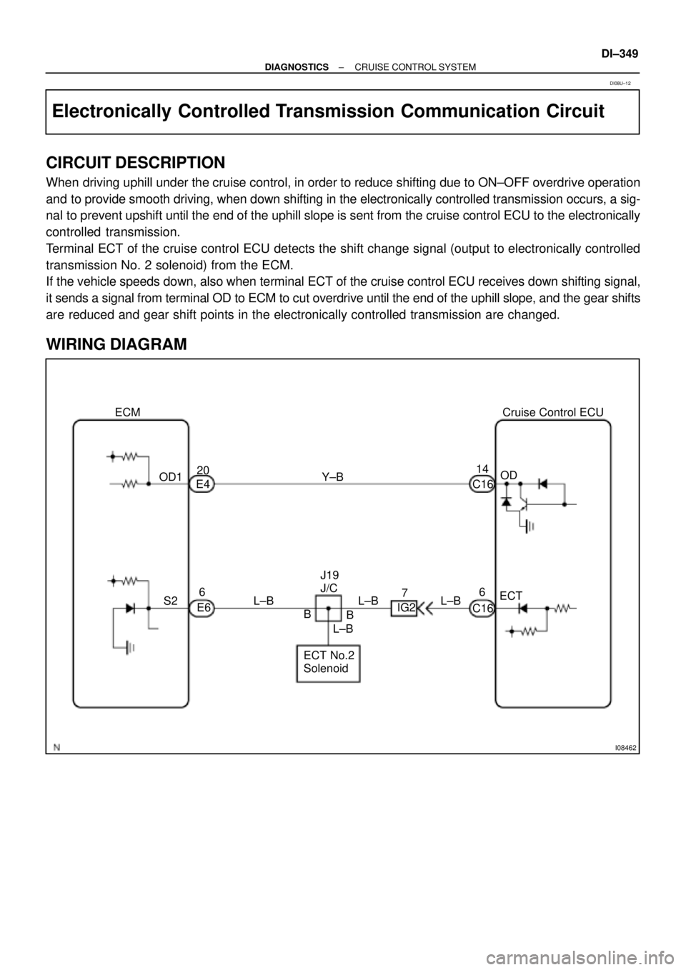
I08462
ECM
OD120
E4
S26
E6L±BY±B
J19
J/C
B
L±BBCruise Control ECU
14
C16OD
ECT 7
IG2
ECT No.2
SolenoidL±B L±B6
C16
± DIAGNOSTICSCRUISE CONTROL SYSTEM
DI±349
Electronically Controlled Transmission Communication Circuit
CIRCUIT DESCRIPTION
When driving uphill under the cruise control, in order to reduce shifting due to ON±OFF overdrive operation
and to provide smooth driving, when down shifting in the electronically controlled transmission occurs, a sig-
nal to prevent upshift until the end of the uphill slope is sent from the cruise control ECU to the electronically
controlled transmission.
Terminal ECT of the cruise control ECU detects the shift change signal (output to electronically controlled
transmission No. 2 solenoid) from the ECM.
If the vehicle speeds down, also when terminal ECT of the cruise control ECU receives down shifting signal,
it sends a signal from terminal OD to ECM to cut overdrive until the end of the uphill slope, and the gear shifts
are reduced and gear shift points in the electronically controlled transmission are changed.
WIRING DIAGRAM
DI08U±12
Page 2502 of 4592
AB0119
I00143
I00174
ON
O/D
(±) (+)
DI±350
± DIAGNOSTICSCRUISE CONTROL SYSTEM
INSPECTION PROCEDURE
1 Check operation of overdrive.
PREPARATION:
Test drive after engine warms up.
CHECK:
Check that overdrive ON e OFF occurs by operation of OD switch ON±OFF.
NG Check and repair electronically controlled
transmission (See page DI±133).
OK
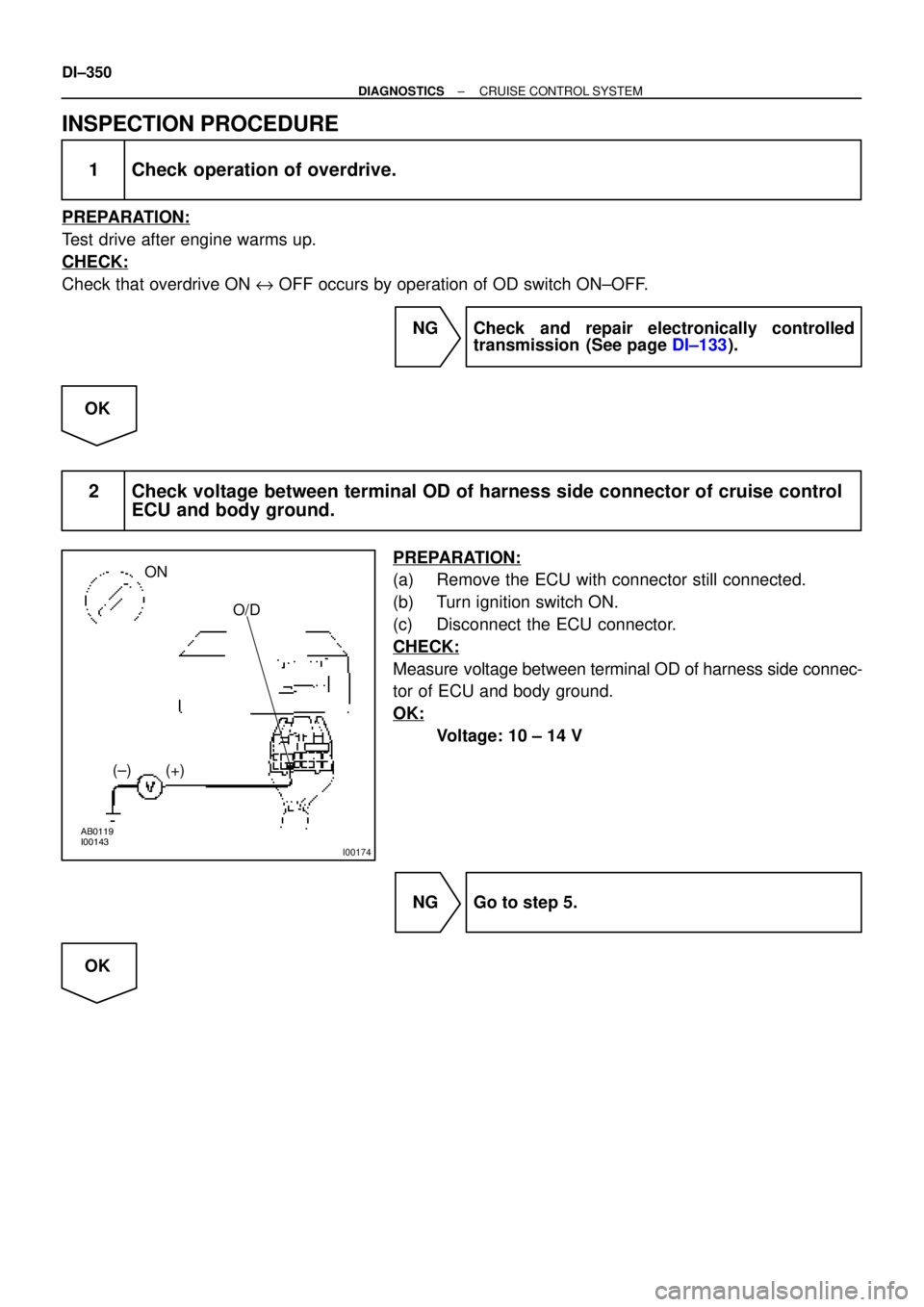
2 Check voltage between terminal OD of harness side connector of cruise control
ECU and body ground.
PREPARATION:
(a) Remove the ECU with connector still connected.
(b) Turn ignition switch ON.
(c) Disconnect the ECU connector.
CHECK:
Measure voltage between terminal OD of harness side connec-
tor of ECU and body ground.
OK:
Voltage: 10 ± 14 V
NG Go to step 5.
OK
Page 2503 of 4592
I00141
ECT
(±) (+)
± DIAGNOSTICSCRUISE CONTROL SYSTEM
DI±351
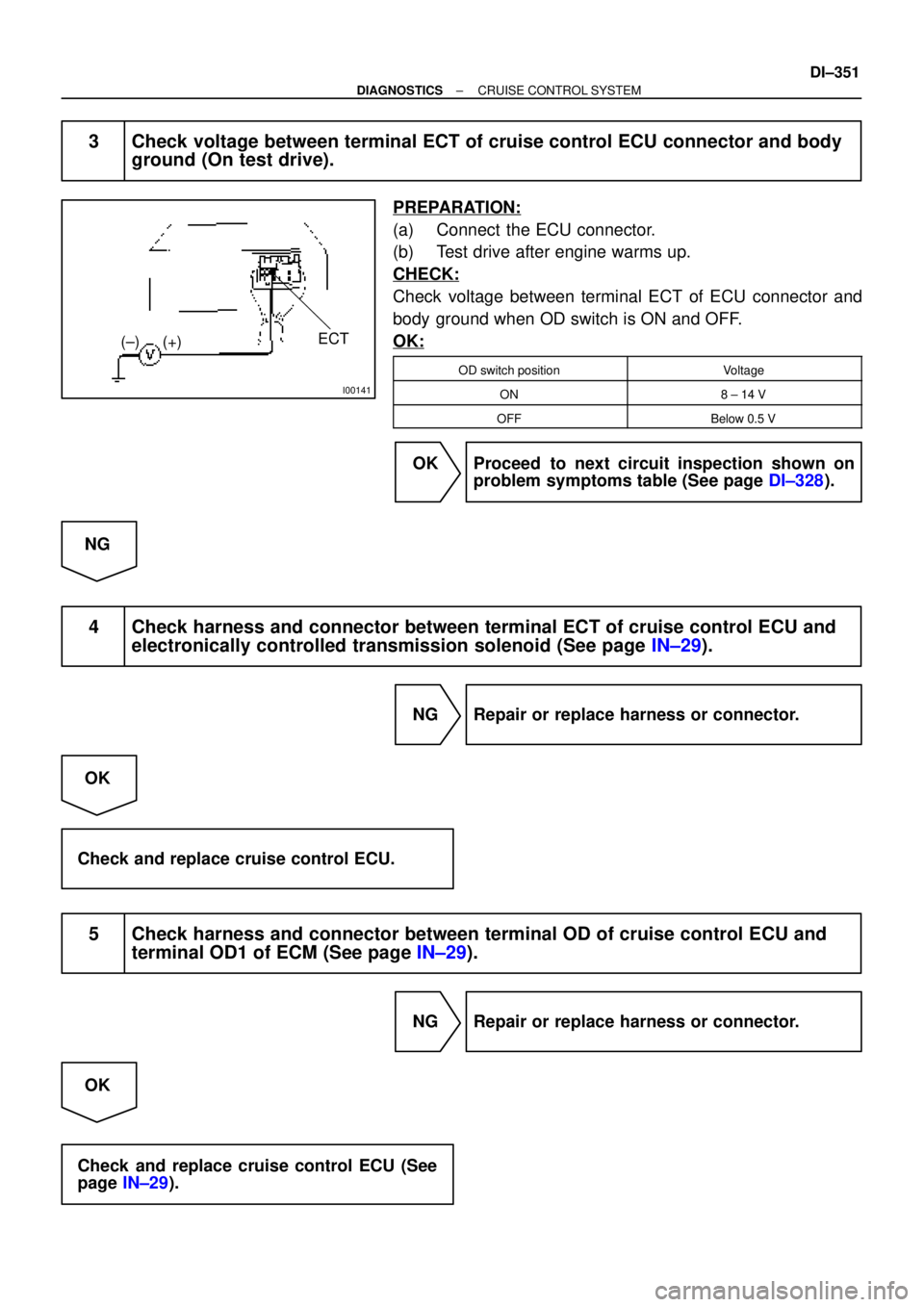
3 Check voltage between terminal ECT of cruise control ECU connector and body
ground (On test drive).
PREPARATION:
(a) Connect the ECU connector.
(b) Test drive after engine warms up.
CHECK:
Check voltage between terminal ECT of ECU connector and
body ground when OD switch is ON and OFF.
OK:
OD switch positionVoltage
ON8 ± 14 V
OFFBelow 0.5 V
OK Proceed to next circuit inspection shown on
problem symptoms table (See page DI±328).
NG
4 Check harness and connector between terminal ECT of cruise control ECU and
electronically controlled transmission solenoid (See page IN±29).
NG Repair or replace harness or connector.
OK
Check and replace cruise control ECU.
5 Check harness and connector between terminal OD of cruise control ECU and
terminal OD1 of ECM (See page IN±29).
NG Repair or replace harness or connector.
OK
Check and replace cruise control ECU (See
page IN±29).
Page 2504 of 4592
I08463
R±LJ19
J/C
DD
R±LPNP Switch
210
B±R9
IG2
B±RJ22
J/C
B±R3
C16Cruise Control ECU
D
R±LR±L 2
IG2F
J24 J24J/C
FInstrument Panel J/B
1
1
1J 1KGAUGE
B±Y
Ignition Switch
AM1 IG1
24
W Instrument Panel J/B
12
1B 1K
B±R
1
F14FL BLOCK
ALT1
F9
B±GFL MAIN
Battery AM1AA DI±352
± DIAGNOSTICSCRUISE CONTROL SYSTEM
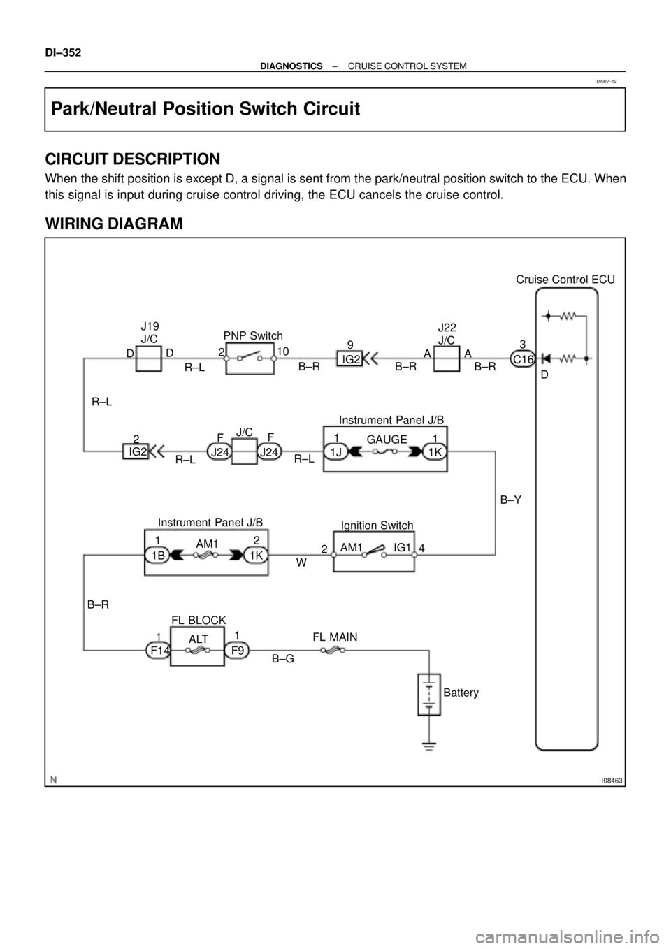
Park/Neutral Position Switch Circuit
CIRCUIT DESCRIPTION
When the shift position is except D, a signal is sent from the park/neutral position switch to the ECU. When
this signal is input during cruise control driving, the ECU cancels the cruise control.
WIRING DIAGRAM
DI08V±12
Page 2505 of 4592
Input SignalIndicator Light
Blinking Pattern
Turn PNP switch
OFF (Shift to posi-
tions except D )LightON
OFFSW ON
SW OFF
± DIAGNOSTICSCRUISE CONTROL SYSTEM
DI±353
INSPECTION PROCEDURE
1 Check starter operation.
CHECK:
Check that the starter operates normally and that the engine starts.
NG Proceed to engine troubleshooting
(See Pub. No. RM654U on page ST±1).
OK
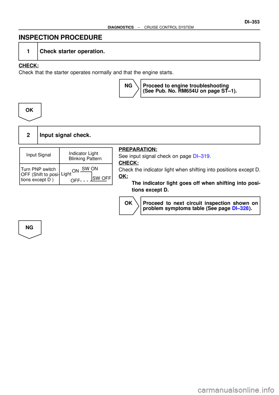
2 Input signal check.
PREPARATION:
See input signal check on page DI±319.
CHECK:
Check the indicator light when shifting into positions except D.
OK:
The indicator light goes off when shifting into posi-
tions except D.
OK Proceed to next circuit inspection shown on
problem symptoms table (See page DI±328).
NG
Page 2506 of 4592
AB0119
I00139
I00175
ON
D
(±) (+)
DI±354
± DIAGNOSTICSCRUISE CONTROL SYSTEM
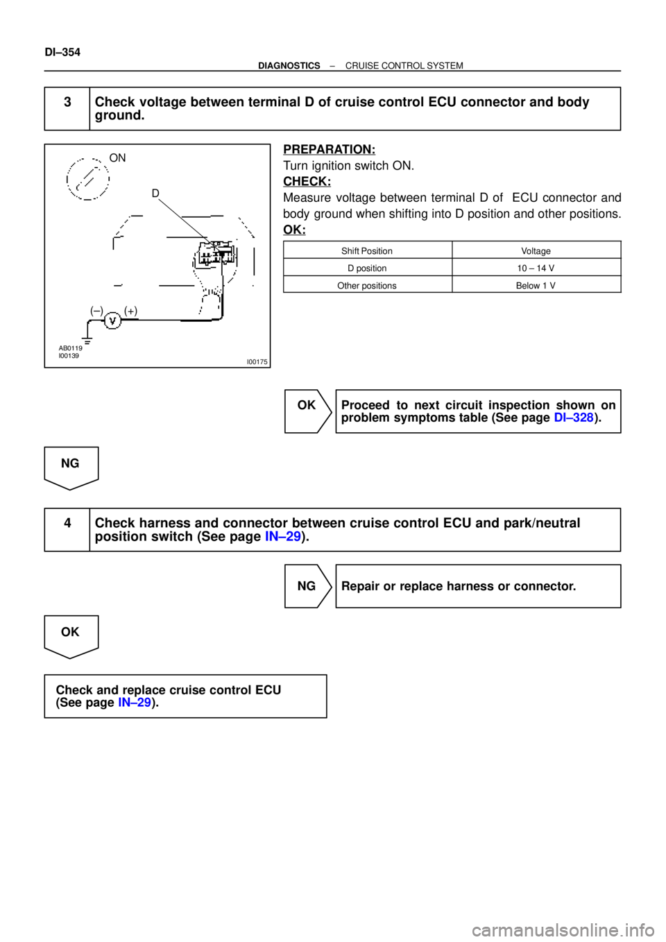
3 Check voltage between terminal D of cruise control ECU connector and body
ground.
PREPARATION:
Turn ignition switch ON.
CHECK:
Measure voltage between terminal D of ECU connector and
body ground when shifting into D position and other positions.
OK:
Shift PositionVoltage
D position10 ± 14 V
Other positionsBelow 1 V
OK Proceed to next circuit inspection shown on
problem symptoms table (See page DI±328).
NG
4 Check harness and connector between cruise control ECU and park/neutral
position switch (See page IN±29).
NG Repair or replace harness or connector.
OK
Check and replace cruise control ECU
(See page IN±29).
Page 2507 of 4592
I08464
Ignition Switch
24
AM1IG1
B±YInstrument Panel J/B
1
1K
B±G
FL MAIN
BatteryECU±IG
1J9
B±RCCJ12
J/C
B±RCruise Control ECU
9
C16
B
GND W
FL BLOCK
1
F91
F14
B±RInstrument Panel J/B
1
1B2
1K AM1
IFJ9
J/C
W±BA
1J7 Instrument Panel J/B
1J8
W±BAA J/C
J6J7
W±B16
C16
± DIAGNOSTICSCRUISE CONTROL SYSTEM
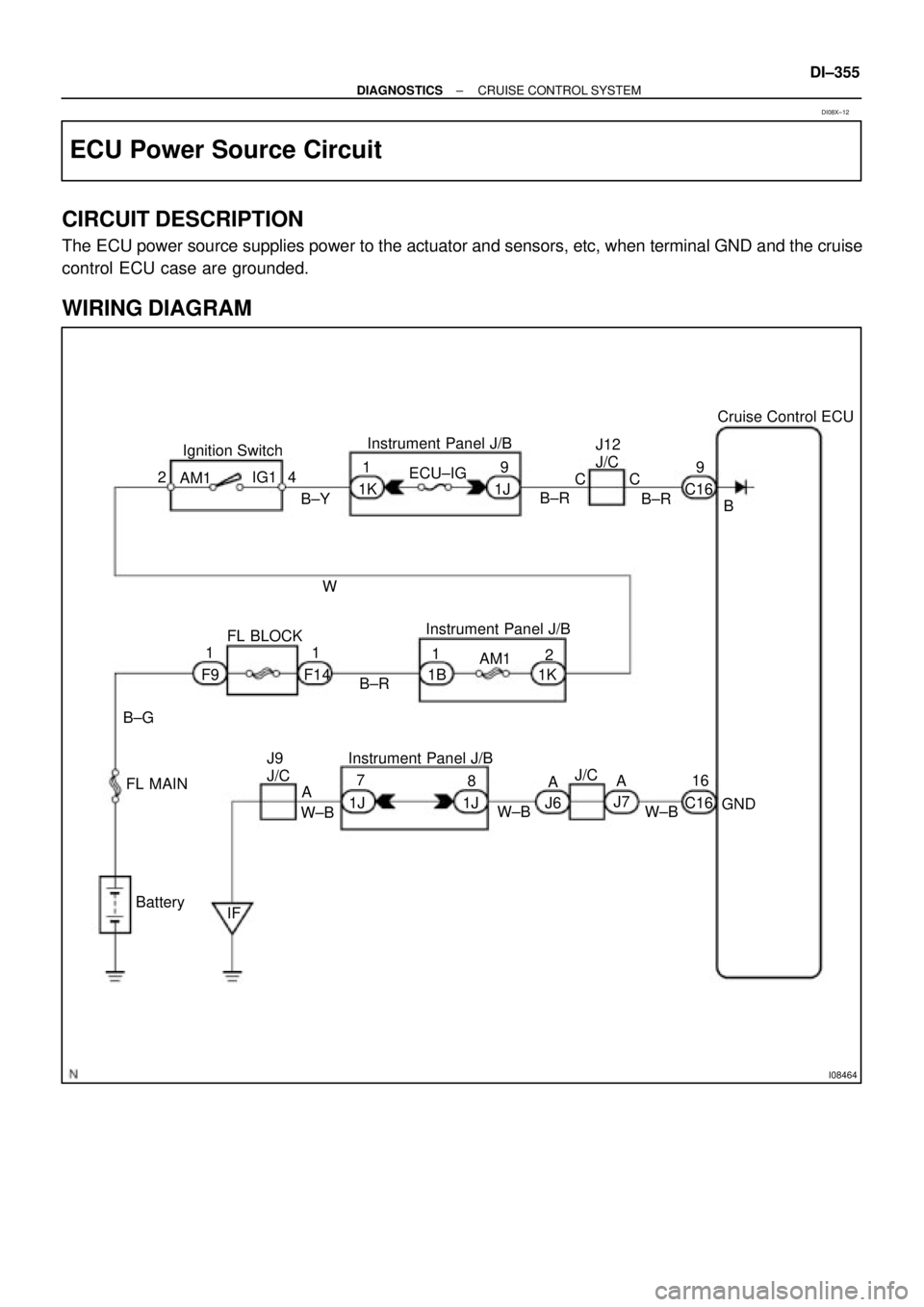
DI±355
ECU Power Source Circuit
CIRCUIT DESCRIPTION
The ECU power source supplies power to the actuator and sensors, etc, when terminal GND and the cruise
control ECU case are grounded.
WIRING DIAGRAM
DI08X±12
Page 2508 of 4592
I00157
Instrument panel junction block No.1:
ECU±IG
Fuse
AB0119
I00147
I00176
ON
GND
(±) (+)B
DI±356
± DIAGNOSTICSCRUISE CONTROL SYSTEM
INSPECTION PROCEDURE
1 Check ECU±IG fuse.
PREPARATION:
Remove the ECU±IG fuse from instrument panel junction block
No.1.
CHECK:
Check continuity of ECU±IG fuse.
OK:
Continuity
NG Check for short in all the harness and compo-
nents connected to ECU±IG fuse.
OK
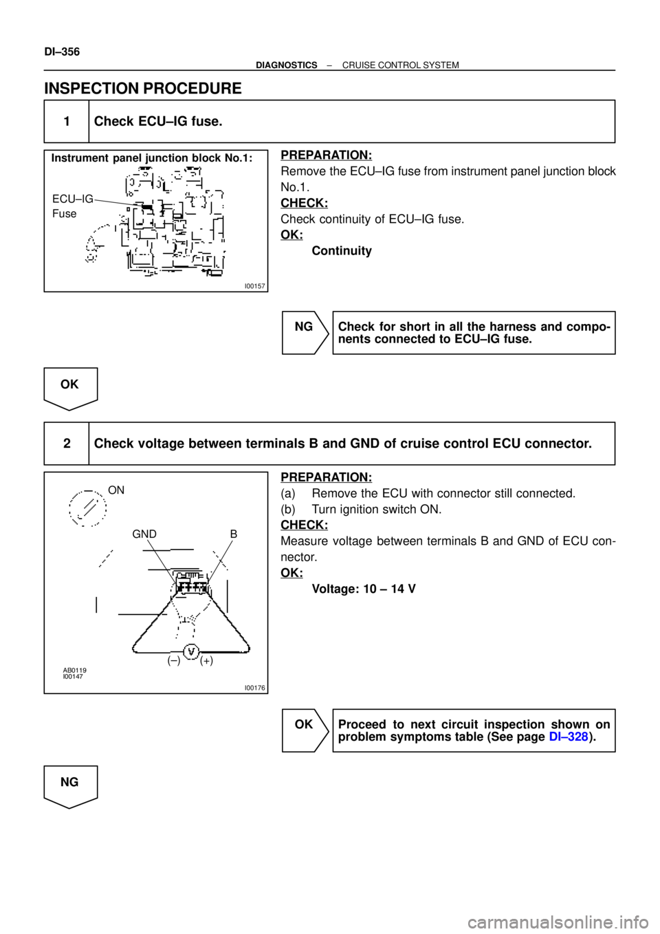
2 Check voltage between terminals B and GND of cruise control ECU connector.
PREPARATION:
(a) Remove the ECU with connector still connected.
(b) Turn ignition switch ON.
CHECK:
Measure voltage between terminals B and GND of ECU con-
nector.
OK:
Voltage: 10 ± 14 V
OK Proceed to next circuit inspection shown on
problem symptoms table (See page DI±328).
NG
Page 2509 of 4592
I00140
GND
± DIAGNOSTICSCRUISE CONTROL SYSTEM
DI±357
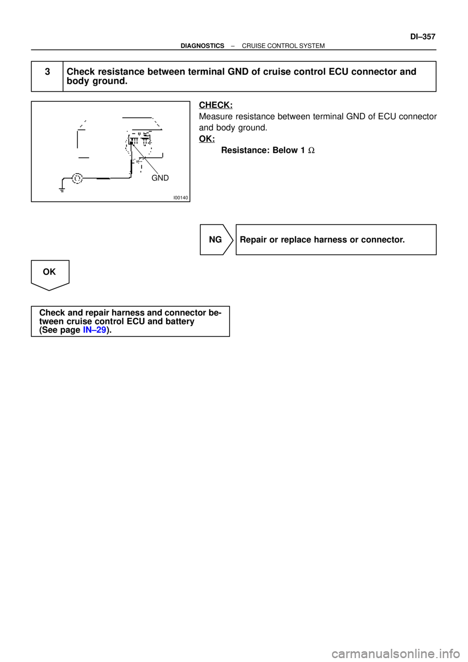
3 Check resistance between terminal GND of cruise control ECU connector and
body ground.
CHECK:
Measure resistance between terminal GND of ECU connector
and body ground.
OK:
Resistance: Below 1 W
NG Repair or replace harness or connector.
OK
Check and repair harness and connector be-
tween cruise control ECU and battery
(See page IN±29).
Page 2510 of 4592
AB0119
I00145
I00177
ON
CMS
(±) (+)
DI±358
± DIAGNOSTICSCRUISE CONTROL SYSTEM
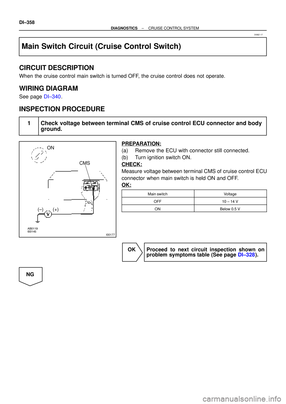
Main Switch Circuit (Cruise Control Switch)
CIRCUIT DESCRIPTION
When the cruise control main switch is turned OFF, the cruise control does not operate.
WIRING DIAGRAM
See page DI±340.
INSPECTION PROCEDURE
1 Check voltage between terminal CMS of cruise control ECU connector and body
ground.
PREPARATION:
(a) Remove the ECU with connector still connected.
(b) Turn ignition switch ON.
CHECK:
Measure voltage between terminal CMS of cruise control ECU
connector when main switch is held ON and OFF.
OK:
Main switchVoltage
OFF10 ± 14 V
ONBelow 0.5 V
OK Proceed to next circuit inspection shown on
problem symptoms table (See page DI±328).
NG
DI08Z±17
Trending: gas type, warning light, air bleeding, brake sensor, brake light, air condition, open gas tank

