TOYOTA CAMRY 2000 Service Owner's Manual
CAMRY 2000
TOYOTA
TOYOTA
https://www.carmanualsonline.info/img/14/57447/w960_57447-0.png
TOYOTA CAMRY 2000 Service Owner's Manual
Page 427 of 4770
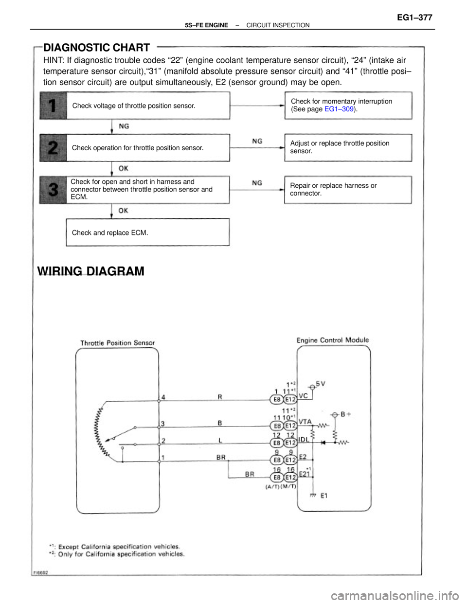
DIAGNOSTIC CHART
HINT: If diagnostic trouble codes ª22º (engine coolant temperature sensor circuit), ª24º (intake air
temperature sensor circuit),ª31º (manifold absolute pressure sensor circuit) and ª41º (throttle posi±
tion sensor circuit) are output simultaneously, E2 (sensor ground) may be open.
Check for open and short in harness and
connector between throttle position sensor and
ECM.Check for momentary interruption
(See page EG1±309).
Adjust or replace throttle position
sensor.
Repair or replace harness or
connector. Check operation for throttle position sensor.Check voltage of throttle position sensor.
WIRING DIAGRAM
Check and replace ECM.
± 5S±FE ENGINECIRCUIT INSPECTIONEG1±377
Page 431 of 4770
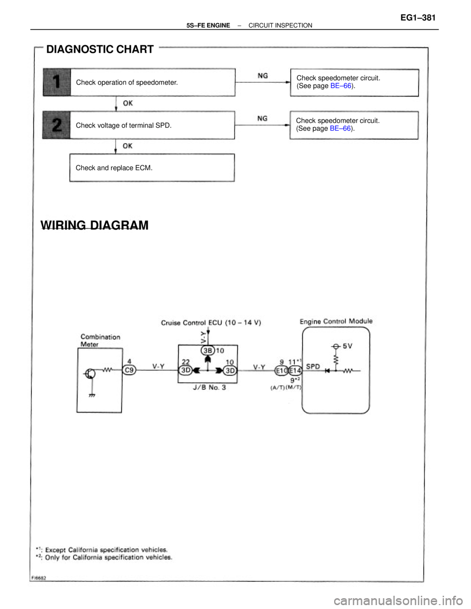
Check speedometer circuit.
(See page BE±66). Check speedometer circuit.
(See page BE±66).
DIAGNOSTIC CHART
Check operation of speedometer.
WIRING DIAGRAM
Check voltage of terminal SPD.
Check and replace ECM.
± 5S±FE ENGINECIRCUIT INSPECTIONEG1±381
Page 433 of 4770
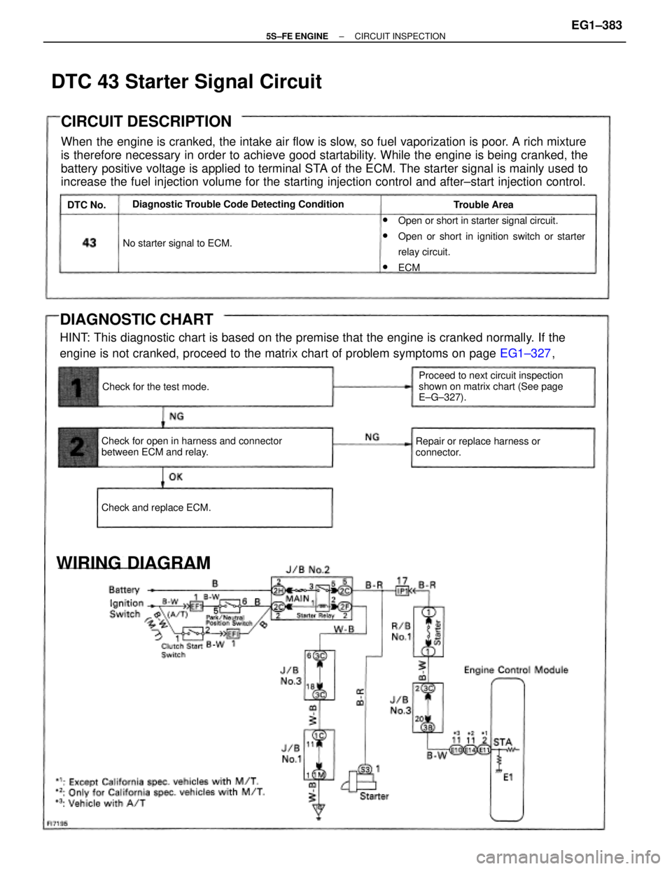
CIRCUIT DESCRIPTION
When the engine is cranked, the intake air flow is slow, so fuel vaporization is poor. A rich mixture
is therefore necessary in order to achieve good startability. While the engine is being cranked, the
battery positive voltage is applied to terminal STA of the ECM. The starter signal is mainly used to
increase the fuel injection volume for the starting injection control and after±start injection control.
DIAGNOSTIC CHART
HINT: This diagnostic chart is based on the premise that the engine is cranked normally. If the
engine is not cranked, proceed to the matrix chart of problem symptoms on page EG1±327, w
Open or short in starter signal circuit.
wOpen or short in ignition switch or starter
relay circuit.
wECM
Check for open in harness and connector
between ECM and relay.Proceed to next circuit inspection
shown on matrix chart (See page
E±G±327). Diagnostic Trouble Code Detecting Condition
Repair or replace harness or
connector.
WIRING DIAGRAM
No starter signal to ECM.
Check and replace ECM.Check for the test mode.Trouble Area
DTC 43 Starter Signal Circuit
DTC No.
± 5S±FE ENGINECIRCUIT INSPECTIONEG1±383
Page 436 of 4770
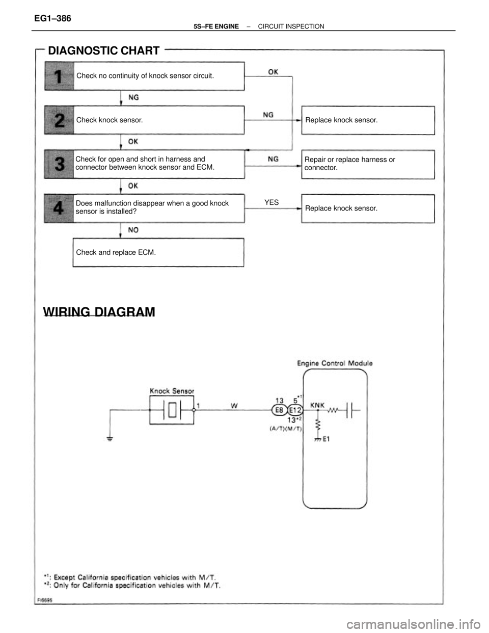
Does malfunction disappear when a good knock
sensor is installed? Check for open and short in harness and
connector between knock sensor and ECM.Repair or replace harness or
connector. Check no continuity of knock sensor circuit.
DIAGNOSTIC CHART
WIRING DIAGRAM
Check and replace ECM.Replace knock sensor.Replace knock sensor. Check knock sensor.
YES
± 5S±FE ENGINECIRCUIT INSPECTIONEG1±386
Page 442 of 4770
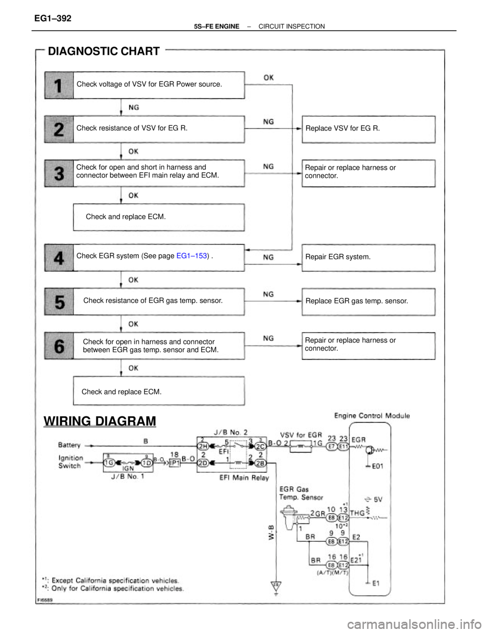
Check for open and short in harness and
connector between EFI main relay and ECM.
Check for open in harness and connector
between EGR gas temp. sensor and ECM. Check voltage of VSV for EGR Power source.
Repair or replace harness or
connector.
Repair or replace harness or
connector. Check resistance of EGR gas temp. sensor. Check EGR system (See page EG1±153) .
WIRING DIAGRAM
DIAGNOSTIC CHART
Check resistance of VSV for EG R.
Replace EGR gas temp. sensor.
Check and replace ECM.Check and replace ECM.Replace VSV for EG R.
Repair EGR system.
± 5S±FE ENGINECIRCUIT INSPECTIONEG1±392
Page 446 of 4770
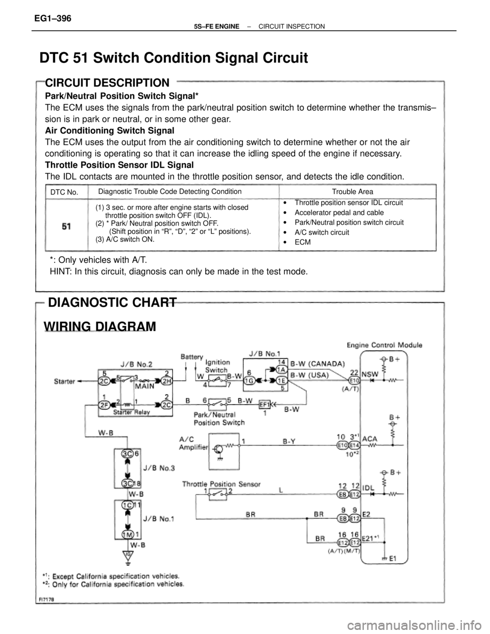
CIRCUIT DESCRIPTION
Park/Neutral Position Switch Signal*
The ECM uses the signals from the park/neutral position switch to determine whether the transmis±
sion is in park or neutral, or in some other gear.
Air Conditioning Switch Signal
The ECM uses the output from the air conditioning switch to determine whether or not the air
conditioning is operating so that it can increase the idling speed of the engine if necessary.
Throttle Position Sensor IDL Signal
The IDL contacts are mounted in the throttle position sensor, and detects the idle condition.
(1) 3 sec. or more after engine starts with closed
throttle position switch OFF (IDL).
(2) * Park/ Neutral position switch OFF.
(Shift position in ªRº, ªDº, ª2º or ªLº positions).
(3) A/C switch ON.
*: Only vehicles with A/T.
HINT: In this circuit, diagnosis can only be made in the test mode.
wThrottle position sensor IDL circuit
wAccelerator pedal and cable
wPark/Neutral position switch circuit
wA/C switch circuit
wECM Diagnostic Trouble Code Detecting Condition
DIAGNOSTIC CHART
WIRING DIAGRAM
Trouble Area
DTC 51 Switch Condition Signal Circuit
DTC No.
± 5S±FE ENGINECIRCUIT INSPECTIONEG1±396
Page 451 of 4770
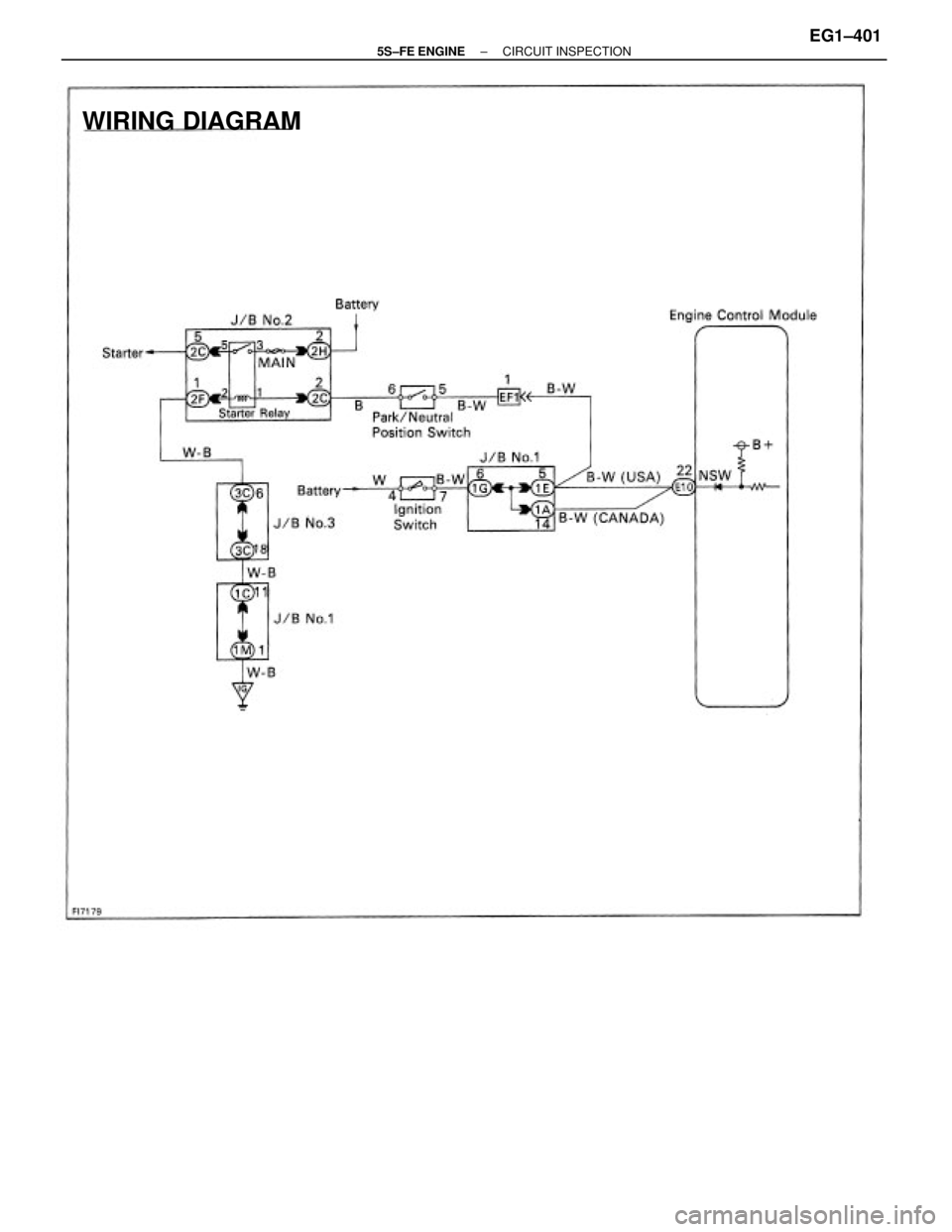
WIRING DIAGRAM
± 5S±FE ENGINECIRCUIT INSPECTIONEG1±401
Page 454 of 4770
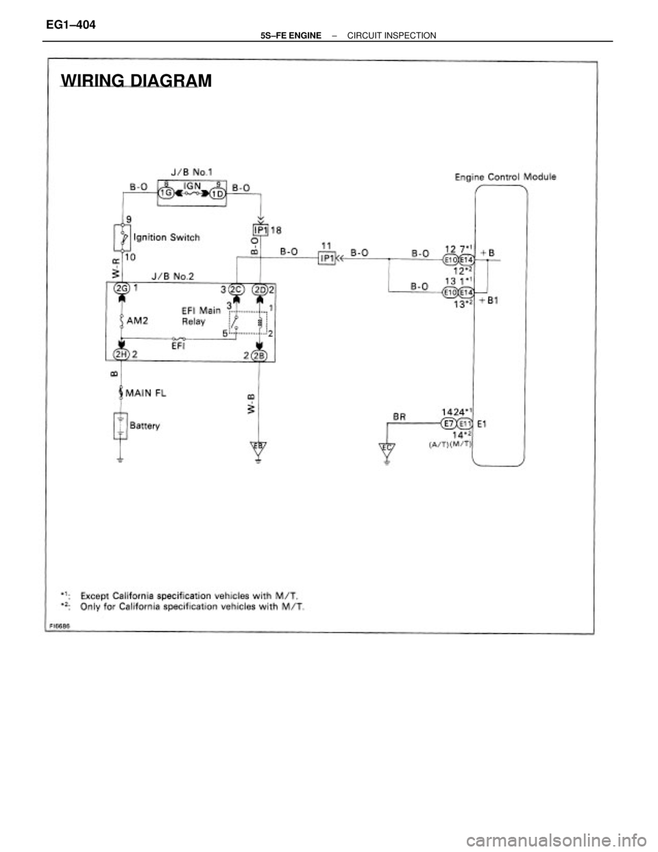
WIRING DIAGRAM
± 5S±FE ENGINECIRCUIT INSPECTIONEG1±404
Page 456 of 4770
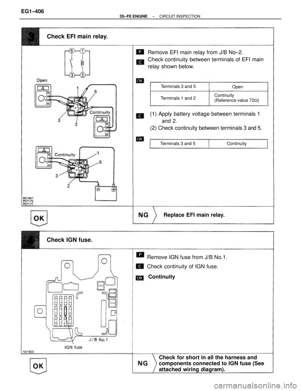
Remove EFI main relay from J/B No±2.
Check continuity between terminals of EFI main
relay shown below.
Remove IGN fuse from J/B No.1.
Check continuity of IGN fuse.(1) Apply battery voltage between terminals 1
and 2.
(2) Check continuity between terminals 3 and 5.
Check for short in all the harness and
components connected to IGN fuse (See
attached wiring diagram).
Check EFI main relay.
Continuity
(Reference value 72�)
Replace EFI main relay.
Check IGN fuse.
Terminals 3 and 5
Terminals 1 and 2
Terminals 3 and 5 ContinuityOpen
Continuity
± 5S±FE ENGINECIRCUIT INSPECTIONEG1±406
Page 457 of 4770
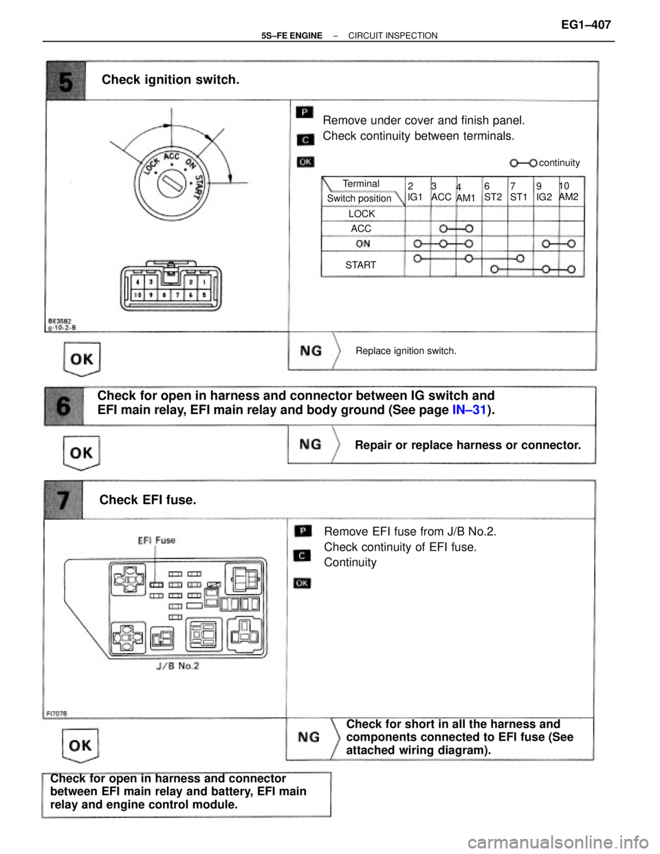
Check for open in harness and connector between IG switch and
EFI main relay, EFI main relay and body ground (See page IN±31).
Remove EFI fuse from J/B No.2.
Check continuity of EFI fuse.
Continuity
Check for open in harness and connector
between EFI main relay and battery, EFI main
relay and engine control module.Check for short in all the harness and
components connected to EFI fuse (See
attached wiring diagram). Remove under cover and finish panel.
Check continuity between terminals.
Repair or replace harness or connector.
Check ignition switch.
Replace ignition switch.
Check EFI fuse.
Switch positioncontinuity
10
AM2 Terminal
4
AM1 3
ACC6
ST27
ST19
IG2
START2
lG1
LOCK
ACC
± 5S±FE ENGINECIRCUIT INSPECTIONEG1±407
