TOYOTA CAMRY HV 2012 Owners Manual
Manufacturer: TOYOTA, Model Year: 2012, Model line: CAMRY HV, Model: TOYOTA CAMRY HV 2012Pages: 536, PDF Size: 6.29 MB
Page 211 of 536
211
2-4. Using other
driving systems
2
When driving
■Reduced effectiveness of the EPS system
The effectiveness of the EPS system is reduced to prevent the system from
overheating when there is frequent steering input over an extended period of
time. The steering wheel may feel heavy as a result. Should this occur,
refrain from excessive steering input or stop the vehicle and turn the hybrid
system off. The EPS system should return to normal within 10 minutes.
■ If the slip indicator comes on...
It may indicate a malfunction in the TRAC, VSC and ABS. Contact your
Toyota dealer.
CAUTION
■ABS does not operate effectively when
●Tires with inadequate gripping ability are used (such as excessively worn
tires on a snow covered road).
● The vehicle hydroplanes while driving at high speed on the wet or slick
road.
■ Stopping distance when the ABS is operating may exceed that of nor-
mal conditions
The ABS is not designed to shorten the vehicle’s stopping distance. Always
maintain a safe distance from the vehicle in front of you in the following situ-
ations:
● When driving on dirt, gravel or snow-covered roads
● When driving with tire chains
● When driving over bumps in the road
● When driving over roads with potholes or roads with uneven surfaces
■ TRAC may not operate effectively when
Directional control and power may not be achievable while driving on slip-
pery road surfaces, even if the TRAC system is operating.
Do not drive the vehicle in conditions where stability and power may be lost.
Page 212 of 536
212 2-4. Using other driving systems
CAUTION
■When the VSC is activated
The slip indicator light flashes. Always drive carefully. Reckless driving may
cause an accident. Exercise particular care when the indicator light flashes.
■ When the TRAC/VSC syst ems are turned off
Be especially careful and drive at a speed appropriate to the road condi-
tions. As these are the systems to ensure vehicle stability and driving force,
do not turn the TRAC/VSC systems off unless necessary.
■ Replacing tires
Make sure that all tires are of the specified size, brand, tread pattern and
total load capacity. In addition, make sure that the tires are inflated to the
recommended tire inflation pressure level.
The ABS, TRAC and VSC systems will not function correctly if different tires
are installed on the vehicle.
Contact your Toyota dealer for further information when replacing tires or
wheels.
■ Handling of tires and suspension
Using tires with any kind of problem or modifying the suspension will affect
the driving assist systems, and may cause a system to malfunction.
Page 213 of 536
213
2-4. Using other driving systems
2
When driving
Hill-start assist control
■Hill-start assist control can be operated when
●The shift lever is in a position other than P.
● The parking brake is not applied.
● The accelerator pedal is not depressed.
■ Hill-start assist control
●While hill-start assist control is operating, the brakes remain automati-
cally applied after the driver releases the brake pedal. The stop lights and
the high mounted stoplight turn on.
● Hill-start assist control operates for about 2 seconds after the brake pedal
is released.
● If the slip indicator does not flash and the buzzer does not sound when
the brake pedal is further depressed, slightly reduce the pressure on the
brake pedal (do not allow the vehicl e to roll backward) and then firmly
depress it again. If the system still does not operate, check if the operat-
ing conditions explained above have been met.
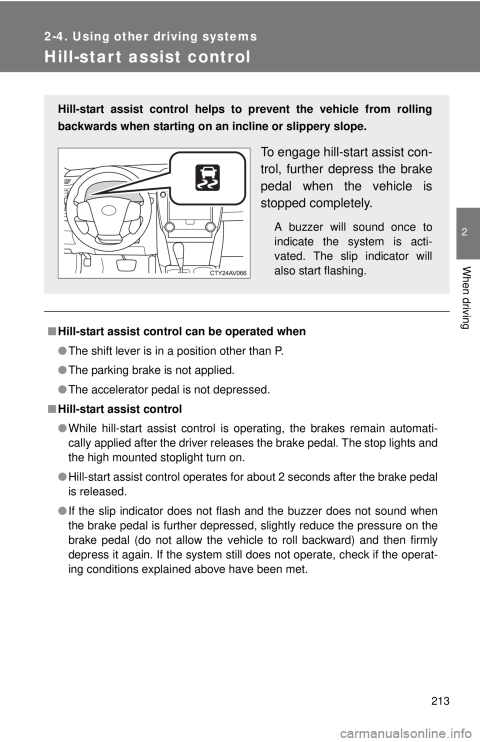
Hill-start assist control helps to prevent the vehicle from rolling
backwards when starting on an incline or slippery slope.
To engage hill-start assist con-
trol, further depress the brake
pedal when the vehicle is
stopped completely.
A buzzer will sound once to
indicate the system is acti-
vated. The slip indicator will
also start flashing.
Page 214 of 536
214 2-4. Using other driving systems
■Hill-start assist control buzzer
●When hill-start assist control is activated, the buzzer will sound once.
● In the following situations, hill-start assist control will be canceled and the
buzzer will sound twice.
• No attempt is made to drive the vehicle within approximately 2 seconds
of releasing the brake pedal.
• The shift lever is moved to P.
• The parking brake is applied.
• The brake pedal is depressed again.
• The brake pedal has been depressed for more than approximately 3 minutes.
■ If the slip indicator comes on
It may indicate a malfunction in the system. Contact your Toyota dealer.
CAUTION
■Hill-start assist control
●Do not overly rely on hill-start assist control. Hill-start assist control may
not operate effectively on extremely st eep inclines or roads covered in ice.
● Unlike the parking brake, hill-start assist control is not intended to hold the
vehicle stationary for an extended period of time. Do not attempt to use
hill-start assist control to hold the vehicle on an incline for an extended
period of time, as doing so may lead to an accident.
Page 215 of 536
215
2-4. Using other driving systems
2
When driving
BSM (Blind Spot Monitor)
: If equipped
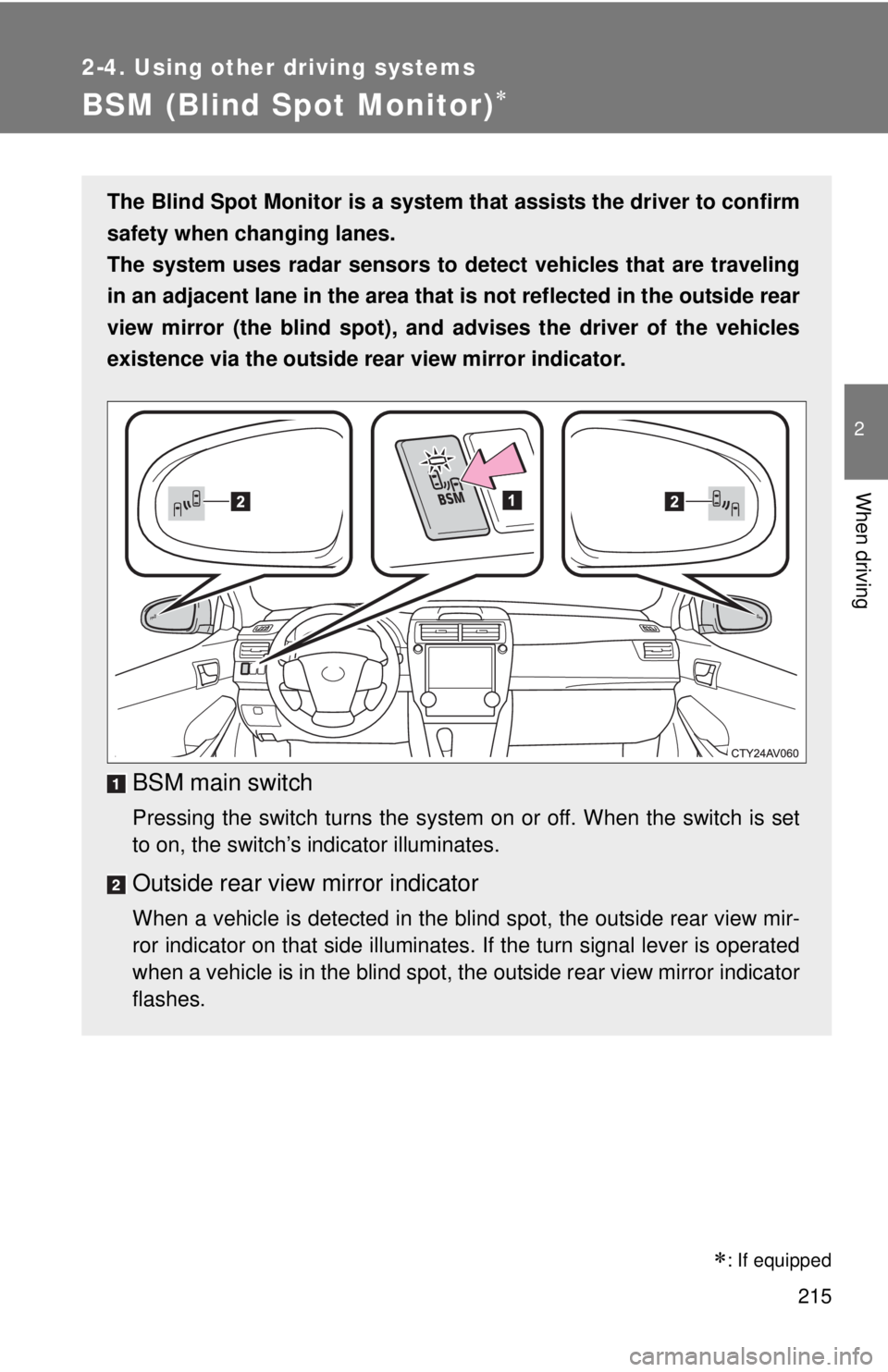
The Blind Spot Monitor is a system that assists the driver to confirm
safety when changing lanes.
The system uses radar sensors to detect vehicles that are traveling
in an adjacent lane in the area that is not reflected in the outside rear
view mirror (the blind spot), an d advises the driver of the vehicles
existence via the outside rear view mirror indicator.
BSM main switch
Pressing the switch turns the system on or off. When the switch is set
to on, the switch’s indicator illuminates.
Outside rear view mirror indicator
When a vehicle is detected in the blind spot, the outside rear view mir-
ror indicator on that side illuminates. If the turn signal lever is operated
when a vehicle is in the blind spot, the outside rear view mirror indicator
flashes.
Page 216 of 536
216 2-4. Using other driving systems
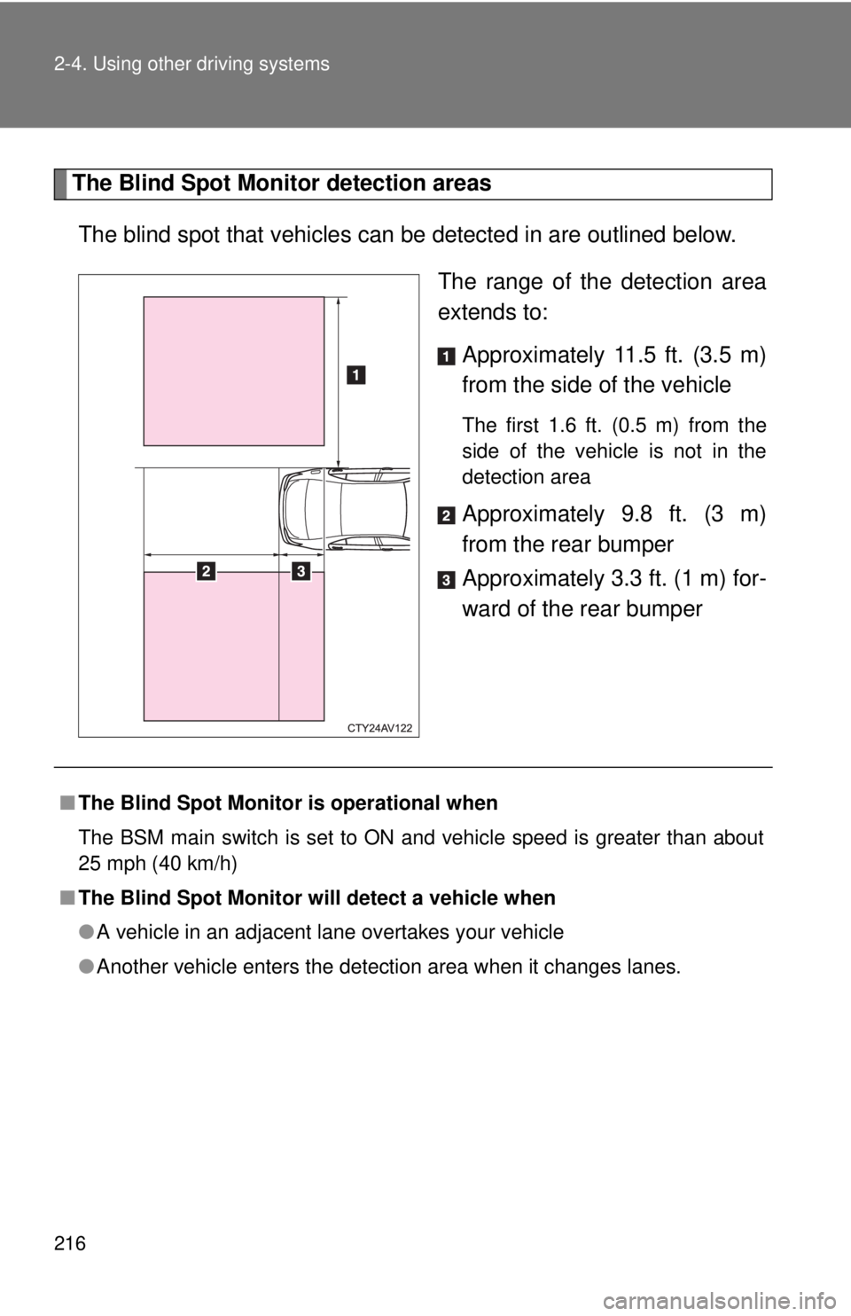
The Blind Spot Monitor detection areasThe blind spot that vehicles can be detected in are outlined below.
The range of the detection area
extends to:Approximately 11.5 ft. (3.5 m)
from the side of the vehicle
The first 1.6 ft. (0.5 m) from the
side of the vehicle is not in the
detection area
Approximately 9.8 ft. (3 m)
from the rear bumper
Approximately 3.3 ft. (1 m) for-
ward of the rear bumper
■The Blind Spot Monitor is operational when
The BSM main switch is set to ON and vehicle speed is greater than about
25 mph (40 km/h)
■ The Blind Spot Monitor will detect a vehicle when
●A vehicle in an adjacent lane overtakes your vehicle
● Another vehicle enters the detection area when it changes lanes.
Page 217 of 536
217
2-4. Using other
driving systems
2
When driving
■Conditions under which the Blind Spot Monitor will not detect a vehicle
The Blind Spot Monitor is not designed to detect the following types of vehi-
cles and/or objects:
●Small motorcycles, bicycles, pedestrians etc.*
● Vehicles traveling in the opposite direction
● Guardrails, walls, signs, parked vehicles and similar stationary objects*
● Following vehicles that are in the same lane*
● Vehicles driving 2 lanes across from your vehicle*
*: Depending on conditions, detection of a vehicle and/or object may occur \
■ Conditions under which the Blind Spot Monitor may not function cor-
rectly
●The Blind Spot Monitor may not detect vehicles correctly in the following
conditions:
• During bad weather such as heavy rain, fog, snow etc.
• When ice or mud etc. is attached to the rear bumper
• When driving on a road surface that is wet due to rain, standing water
etc.
• When there is a significant difference in speed between your vehicle and the vehicle that enters the detection area
• When a vehicle is in the detection area from a stop and remains in the detection area as your vehicle accelerates
• When driving up or down consecutive steep inclines, such as hills, a dip in the road etc.
• When multiple vehicles approach with only a small gap between each vehicle
• When vehicle lanes are wide, and the vehicle in the next lane is too far away from your vehicle
• When the vehicle that enters the detection area is traveling at about the same speed as your vehicle
• When there is a significant difference in height between your vehicle and the vehicle that enters the detection area.
• Directly after the BSM switch is set to on.
Page 218 of 536
218 2-4. Using other driving systems
●Instances of the Blind Spot Monitor unnecessarily detecting a vehicle
and/or object may increase under the following conditions:
• When there is only a short distance between your vehicle and a guard-
rail, wall etc.
• When there is only a short distance between your vehicle and a follow- ing vehicle.
• When vehicle lanes are narrow and a vehicle driving 2 lanes across from your vehicle enters the detection area
■ The outside rear view mirror indicators visibility
When under strong sunlight, the outside rear view mirror indicator may be
difficult to see.
■ When there is a malfunction in the system
If a system malfunction is detected due to any of the following reasons,
warning messages will be displayed: ( P. 425)
● There is a malfunction with the sensors
● The sensors have become dirty
● The outside temperature is extremely high or low
● The sensor voltage has become abnormal
■ Certification for the BSM
FCC ID: OAYBSDTX
This device complies with part 15 of the FCC Rules. Operation is subject to
the following three conditions:
(1) This device may not cause harmful interference.
(2) This device must accept any interference received, including interference
that may cause undesired operation.
(3) This device may only work when the vehicle is in operation pursuant to § 15.252 (a) (4).
FCC WARNING
Changes or modifications not expressly approved by the party responsible
for compliance could void the user’s authority to operate the equipment.
Page 219 of 536
219
2-4. Using other
driving systems
2
When driving
CAUTION
■Cautions regarding the use of the system
The driver is solely responsible for safe driving. Always drive safely, taking
care to observe your surroundings.
The Blind Spot Monitor is a supplementary system which alerts the driver
that a vehicle is present in the blind spot. Do not overly rely on the Blind Spot
Monitor. The system cannot judge if it is safe to change lanes, therefore over
reliance could cause an accident resulting in death or serious injury. Accord-
ing to conditions, the system may not function correctly. Therefore the
driver’s own visual confirmation of safety is necessary.
■ Handling the radar sensor
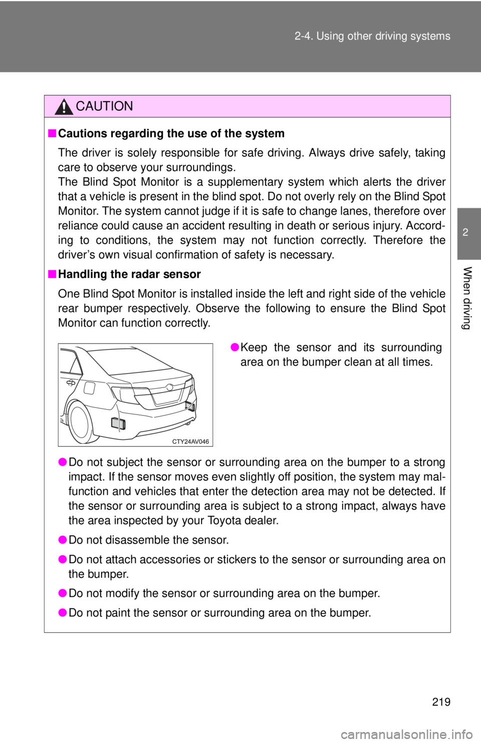
One Blind Spot Monitor is installed inside the left and right side of the vehicle
rear bumper respectively. Observe the following to ensure the Blind Spot
Monitor can function correctly.
●Do not subject the sensor or surrounding area on the bumper to a strong
impact. If the sensor moves even slightly off position, the system may mal-
function and vehicles that enter the detection area may not be detected. If
the sensor or surrounding area is subject to a strong impact, always have
the area inspected by your Toyota dealer.
● Do not disassemble the sensor.
● Do not attach accessories or stickers to the sensor or surrounding area on
the bumper.
● Do not modify the sensor or surrounding area on the bumper.
● Do not paint the sensor or surrounding area on the bumper.
●Keep the sensor and its surrounding
area on the bumper clean at all times.
Page 220 of 536
220
2-5. Driving information
Cargo and luggage
Capacity and distributionCargo capacity depends on the total weight of the occupants.
(Cargo capacity) = (Total load capacity) - (Total weight of occupants)
Steps for Determining Correct Load Limit
(1)Locate the statement “The co mbined weight of occupants and
cargo should never exceed XXX kg or XXX lbs.” on your vehicle's
placard.
(2)Determine the combined weight of the driver and passengers that
will be riding in your vehicle.
(3)Subtract the combined weight of the driver and passengers from XXX kg or XXX lbs.
(4)The resulting figure equals the available amount of cargo and lug- gage load capacity.
For example, if the “XXX” amount equals 1400 lbs. and there will
be five 150 lb passengers in your vehicle, the amount of available
cargo and luggage load capacity is 650 lbs. (1400 - 750 (5 150) =
650 lbs.)
(5)Determine the combined weight of luggage and cargo being loaded on the vehicle. That weight may not safely exceed the avail-
able cargo and luggage load capacity calculated in Step 4.
Take notice of the following information about storage precau-
tions, cargo capacity and load:
● Stow cargo and luggage in the trunk whenever possible.
● Be sure all items are secured in place.
● To maintain vehicle balance while driving, position luggage
evenly within the luggage compartment.
● For better fuel economy, do no t carry unnecessary weight.