ECU TOYOTA CAMRY HYBRID 2010 XV40 / 8.G Owner's Guide
[x] Cancel search | Manufacturer: TOYOTA, Model Year: 2010, Model line: CAMRY HYBRID, Model: TOYOTA CAMRY HYBRID 2010 XV40 / 8.GPages: 497, PDF Size: 9.63 MB
Page 279 of 497
278
3-4. Using the hands-free phone system (for cellular phone)
Security and system setup
Setting or changing the PIN■ Setting a PIN
Select “Set PIN” by using a voice command or .
Enter a PIN by using a voice command or .
When using , input the code 1 digit at a time.
To enter the menu of each setting, follow the steps below:
■ Security setting items and operation procedure
● Setting or changing t he PIN (Personal Identification Number)
1. “Setup” 2. “Security” 3. “Set PIN”
● Locking the phone book
1. “Setup” 2. “Security” 3. “Phonebook Lock”
● Unlocking the phone book
1. “Setup” 2. “Security” 3. “Phonebook Unlock”
■ System setup items and operation procedure
●Setting voice guidance volume
1. “Setup” 2. “System Setup” 3. “Guidance Volume”
● Initialization
1. “Setup” 2. “System Setup” 3. “Initialize”
can only be used for system setup operation.
STEP1
STEP2
Page 282 of 497
281
3-4. Using the hand
s-free phone system (for cellular phone)
3
Interior features
■Initialization
●The following data in the system can be initialized:
• Phone book
• Outgoing and incoming call history
• Speed dials
• Registered cellular phone data
• Security code
● Once the initialization has been completed, the data cannot be restored
to its original state.
■ When the phone book is locked
The following functions cannot be used:
●Dialing by inputting a name
● Speed dialing
● Dialing a number stored in the call history memory
● Using the phone book
Page 310 of 497
309
3-7. Other interior features
3
Interior features
Floor mat
CAUTION
■When inserting the floor mat
Observe the following precautions.
Failure to do so may result in the floor mat slipping and interfering wi\
th the
movement of the pedals during driving, resulting in an accident.
●Make sure the floor mat is properly placed on the vehicle carpet and the
correct side faces upward.
● Do not place floor mats on the top of existing mats.
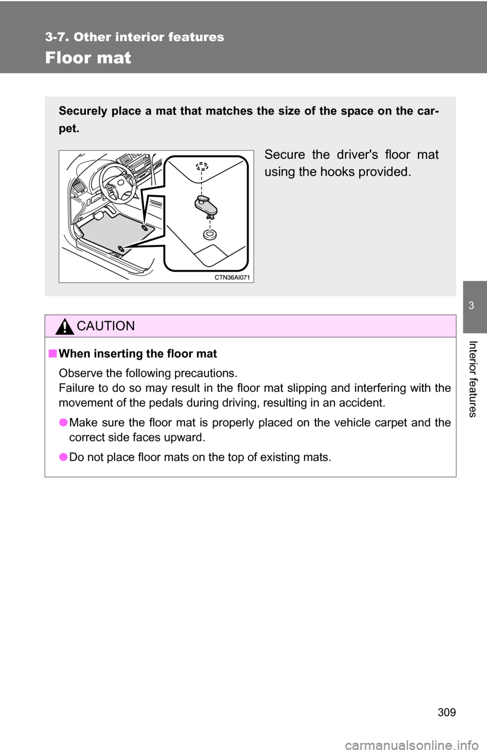
Securely place a mat that matches the size of the space on the car-
pet.
Secure the driver's floor mat
using the hooks provided.
Page 313 of 497
312
3-7. Other interior features
Garage door opener
The garage door opener (HomeLink Universal Transceiver) is manufac-
tured under license from HomeLink.
Programming HomeLink (for U.S. owners)
To ensure correct programming into the HomeLink
, install a new
battery in the hand-held transmitter prior to programming. Failure to
install a new battery into the hand- held transmitter will affect both the
range and accuracy of the HomeLink
in your vehicle.
The battery side of the hand-held transmitter must be pointed away
from the HomeLink
during the programming process.
The HomeLink
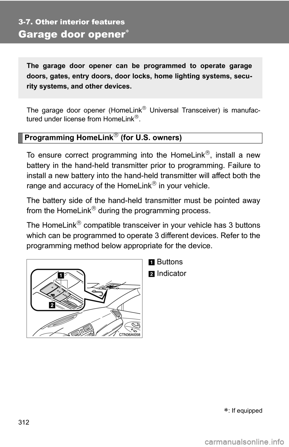
compatible transceiver in your vehicle has 3 buttons
which can be programmed to operate 3 different devices. Refer to the
programming method below appropriate for the device.
Buttons
Indicator
The garage door opener can be programmed to operate garage
doors, gates, entry doors, door locks, hom e lighting systems, secu-
rity systems, and other devices.
: If equipped
Page 316 of 497
315
3-7. Other interior features
3
Interior features
Test the operation of HomeLink by pressing the newly pro-
grammed button. Check to see if the gate/device operates
correctly.
Repeat the steps above to program another device for each of
the remaining HomeLink
buttons.
■ Programming other devices
To program other devices such as home security systems, home
door locks or lighting, contact your authorized Toyota dealer for
assistance.
■ Reprogramming a button
The individual HomeLink
buttons cannot be erased but can be
reprogrammed. To reprogram a bu tton, follow the “Programming”
instructions.
Operating HomeLink
Press the appropriate HomeLink button. The HomeLink indicator
light on the HomeLink transceiver should turn on.
HomeLink continues to send a signal for up to 20 seconds as long as the
button is pressed.
Erasing the entire HomeLink memory (all three programs)
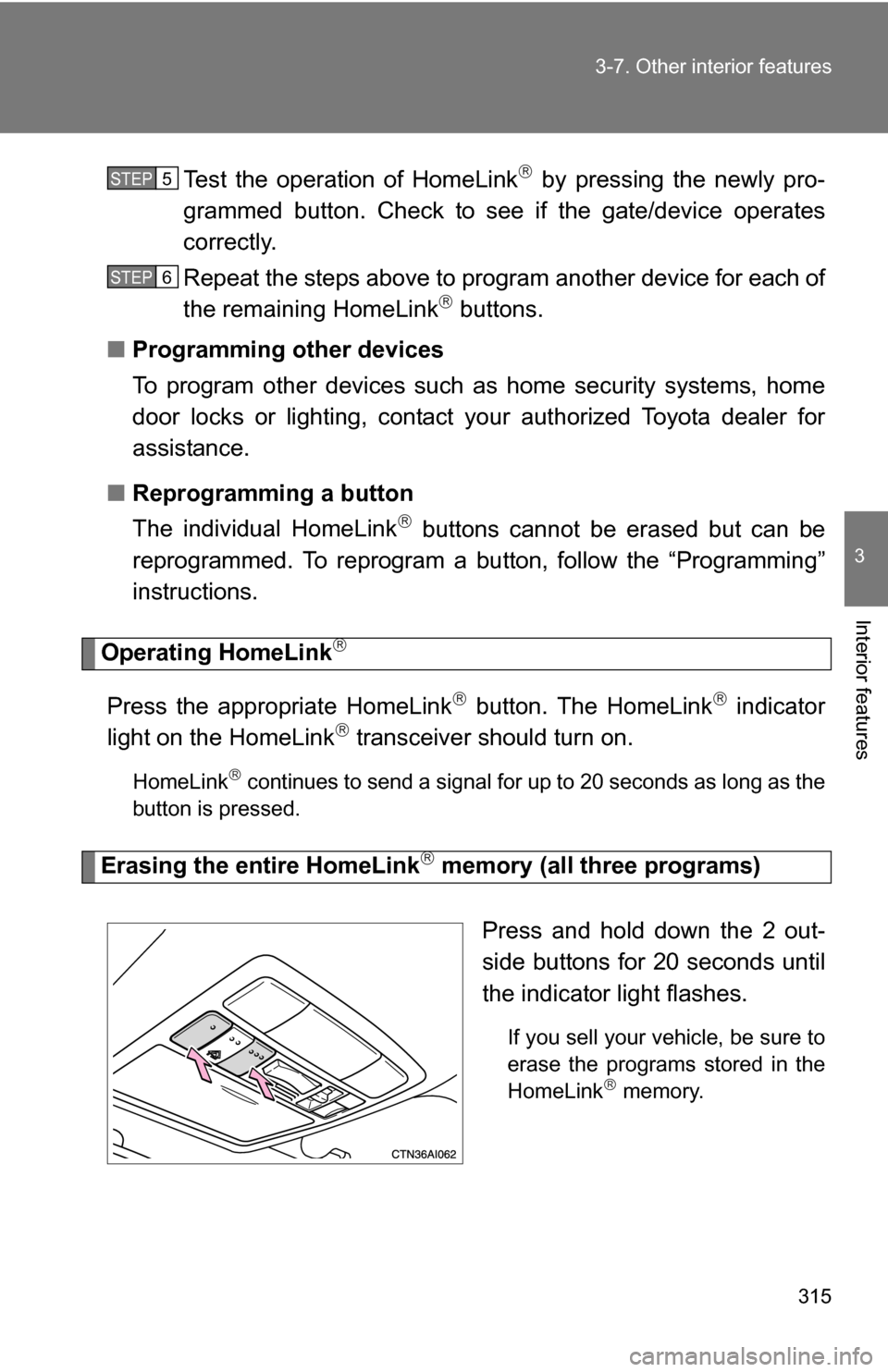
Press and hold down the 2 out-
side buttons for 20 seconds until
the indicator light flashes.
If you sell your vehicle, be sure to
erase the programs stored in the
HomeLink
memory.
STEP5
STEP6
Page 321 of 497
320 3-7. Other interior features
CAUTION
■While driving the vehicle
Do not adjust the display. Be sure to adjust the display only when the vehicle
is stopped.
■ When doing the circling calibration
Be sure to secure a wide space, and watch out for people and vehicles in the
neighborhood. Do not violate any local traffic rules while performing circling
calibration.
NOTICE
■To avoid compass malfunctions
Do not place magnets or any metal objects near the anti-glare inside rear
view mirror.
Doing this may cause a malfunction of the compass sensor.
■ To ensure normal operation of the compass
●Do not perform circling calibration of the compass in a place where the
earth's magnetic field is subject to interference by artificial magnetic fields.
● During calibration, do not operate electric systems (moon roof, power win-
dows, etc.) as they may interfere with the calibration.
Page 331 of 497
330 4-2. Maintenance
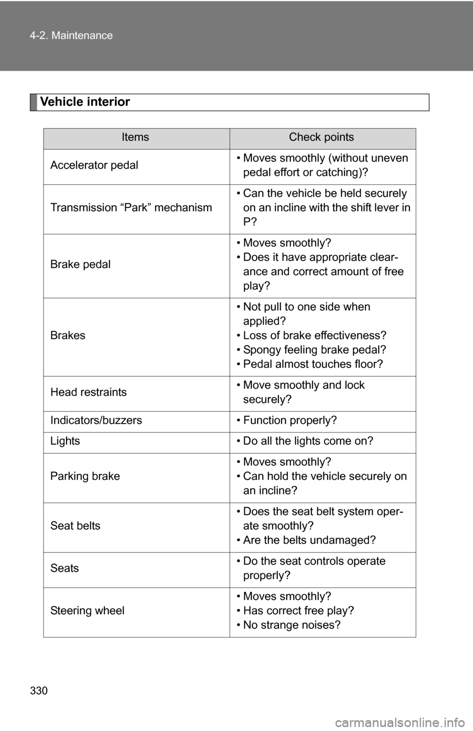
Vehicle interior
ItemsCheck points
Accelerator pedal • Moves smoothly (without uneven
pedal effort or catching)?
Transmission “Park” mechanism • Can the vehicle be held securely
on an incline with the shift lever in
P?
Brake pedal • Moves smoothly?
• Does it have appropriate clear-
ance and correct amount of free
play?
Brakes • Not pull to one side when
applied?
• Loss of brake effectiveness?
• Spongy feeling brake pedal?
• Pedal almost touches floor?
Head restraints • Move smoothly and lock
securely?
Indicators/buzzers • Function properly?
Lights • Do all the lights come on?
Parking brake • Moves smoothly?
• Can hold the vehicle securely on
an incline?
Seat belts • Does the seat belt system oper-
ate smoothly?
• Are the belts undamaged?
Seats • Do the seat controls operate
properly?
Steering wheel • Moves smoothly?
• Has correct free play?
• No strange noises?
Page 378 of 497
377
4-3. Do-it-yourself maintenance
4
Maintenance and care
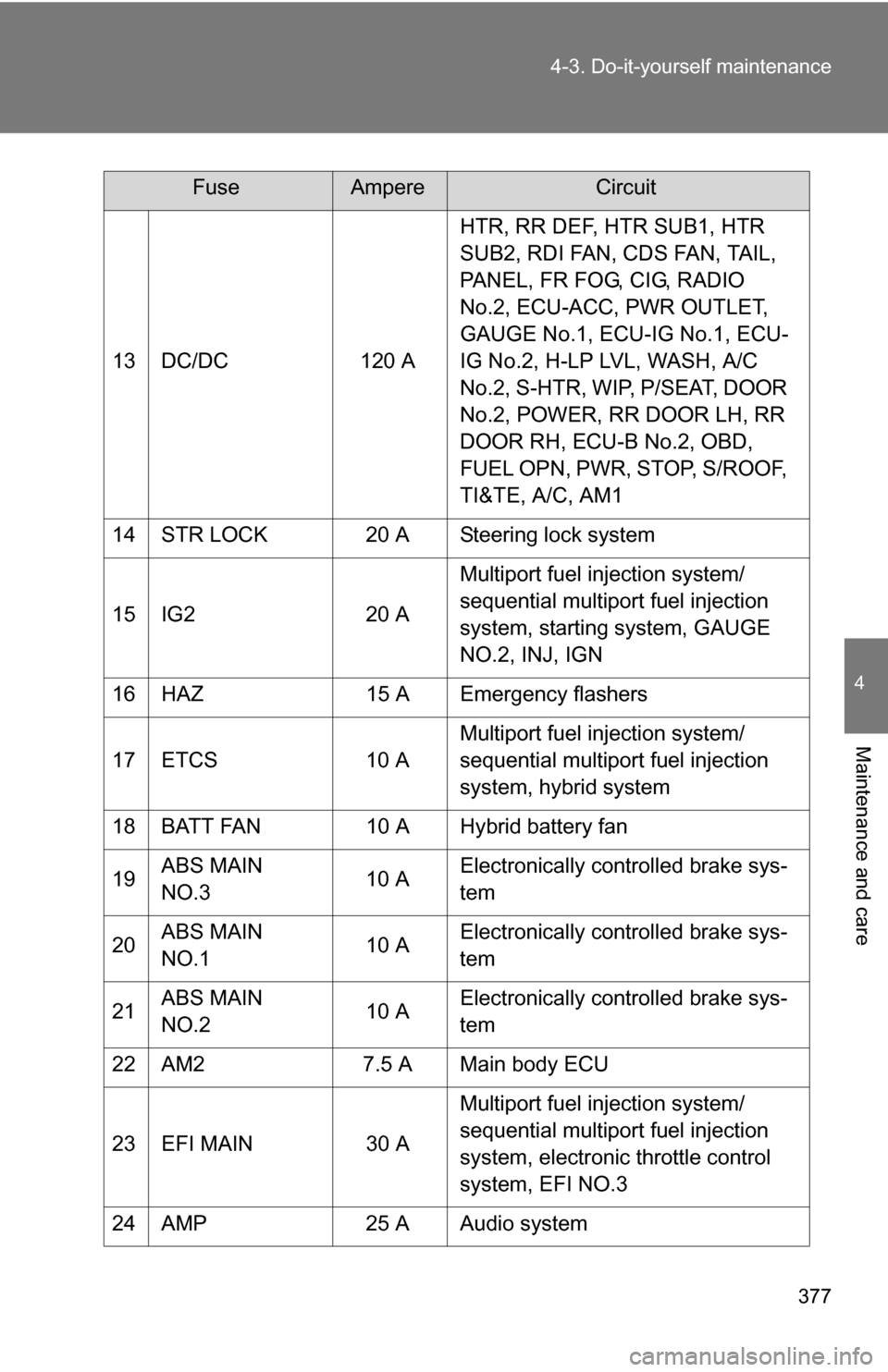
13 DC/DC
120 AHTR, RR DEF, HTR SUB1, HTR
SUB2, RDI FAN, CDS FAN, TAIL,
PANEL, FR FOG, CIG, RADIO
No.2, ECU-ACC, PWR OUTLET,
GAUGE No.1, ECU-IG No.1, ECU-
IG No.2, H-LP LVL, WASH, A/C
No.2, S-HTR, WIP, P/SEAT, DOOR
No.2, POWER, RR DOOR LH, RR
DOOR RH, ECU-B No.2, OBD,
FUEL OPN, PWR, STOP, S/ROOF,
TI&TE, A/C, AM1
14 STR LOCK 20 A Steering lock system
15 IG2 20 AMultiport fuel injection system/
sequential multiport fuel injection
system, starting system, GAUGE
NO.2, INJ, IGN
16 HAZ 15 A Emergency flashers
17 ETCS 10 AMultiport fuel injection system/
sequential multiport fuel injection
system, hybrid system
18 BATT FAN 10 A Hybrid battery fan
19 ABS MAIN
NO.3 10 AElectronically controlled brake sys-
tem
20 ABS MAIN
NO.1 10 AElectronically controlled brake sys-
tem
21 ABS MAIN
NO.2 10 AElectronically controlled brake sys-
tem
22 AM2 7.5 A Main body ECU
23 EFI MAIN 30 AMultiport fuel injection system/
sequential multiport fuel injection
system, electronic throttle control
system, EFI NO.3
24 AMP 25 A Audio system
FuseAmpereCircuit
Page 379 of 497
378 4-3. Do-it-yourself maintenance
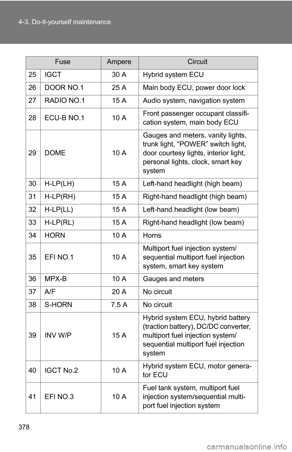
25 IGCT30 A Hybrid system ECU
26 DOOR NO.1 25 A Main body ECU, power door lock
27 RADIO NO.1 15 A Audio system, navigation system
28 ECU-B NO.1 10 A Front passenger occupant classifi-
cation system, main body ECU
29 DOME 10 AGauges and meters, vanity lights,
trunk light, “POWER” switch light,
door courtesy lights, interior light,
personal lights, clock, smart key
system
30 H-LP(LH) 15 A Left-hand headlight (high beam)
31 H-LP(RH) 15 A Right-hand headlight (high beam)
32 H-LP(LL) 15 A Left-hand headlight (low beam)
33 H-LP(RL) 15 A Right-hand headlight (low beam)
34 HORN 10 A Horns
35 EFI NO.1 10 AMultiport fuel injection system/
sequential multiport fuel injection
system, smart key system
36 MPX-B 10 A Gauges and meters
37 A/F 20 A No circuit
38 S-HORN 7.5 A No circuit
39 INV W/P 15 AHybrid system ECU, hybrid battery
(traction battery), DC/DC converter,
multiport fuel injection system/
sequential multiport fuel injection
system
40 IGCT No.2 10 A Hybrid system ECU, motor genera-
tor ECU
41 EFI NO.3 10 AFuel tank system, multiport fuel
injection system/sequential multi-
port fuel injection system
FuseAmpereCircuit
Page 380 of 497
379
4-3. Do-it-yourself maintenance
4
Maintenance and care
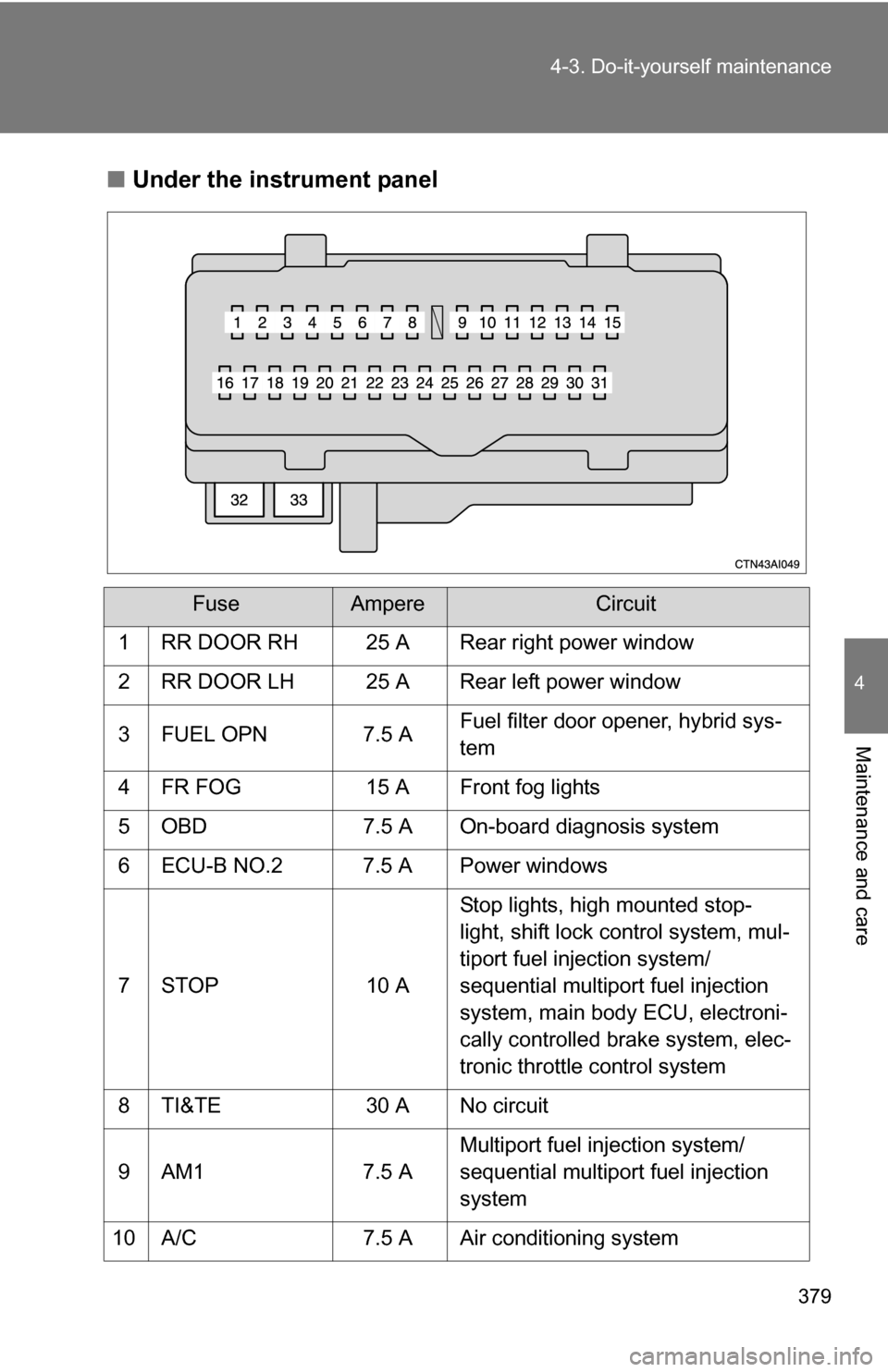
■
Under the instrument panel
FuseAmpereCircuit
1 RR DOOR RH 25 A Rear right power window
2 RR DOOR LH 25 A Rear left power window
3 FUEL OPN 7.5 A Fuel filter door opener, hybrid sys-
tem
4 FR FOG 15 A Front fog lights
5 OBD 7.5 A On-board diagnosis system
6 ECU-B NO.2 7.5 A Power windows
7 STOP 10 A Stop lights, high mounted stop-
light, shift lock control system, mul-
tiport fuel injection system/
sequential multiport fuel injection
system, main body ECU, electroni-
cally controlled brake system, elec-
tronic throttle control system
8 TI&TE 30 A No circuit
9 AM1 7.5 A Multiport fuel injection system/
sequential multiport fuel injection
system
10 A/C 7.5 A Air conditioning system