display TOYOTA CAMRY HYBRID 2021 Owners Manual (in English)
[x] Cancel search | Manufacturer: TOYOTA, Model Year: 2021, Model line: CAMRY HYBRID, Model: TOYOTA CAMRY HYBRID 2021Pages: 624, PDF Size: 15.98 MB
Page 2 of 624

TABLE OF CONTENTS2
For your information....................... 6
Reading this manual .................... 12
How to search .............................. 13
Pictorial index .............................. 14
1-1. For safe useBefore driving ...................... 24
For safe driving ................... 26
Seat belts ............................ 28
SRS airbags ........................ 34
Front passenger occupant classification
system............................... 47
Exhaust gas precautions ..... 52
1-2. Child safety Riding with children ............. 53
Child restraint systems ........ 54
1-3. Emergency assistance Safety Connect.................... 73
1-4. Hybrid system Hybrid system features ....... 79
Hybrid system precautions ....................... 83
1-5. Theft deterrent system Immobilizer system ............. 90
Alarm ................................... 92 2. Instrument cluster
Warning lights and indicators ........................... 96
Gauges and meters ........... 102
Multi-information display (4.2-inch display) ............. 106
Multi-information display (7-inch display) ................ 119
Head-up display................. 138
Energy monitor/ consumption screen ........ 144
3-1. Key information Keys................................... 154
3-2. Opening, closing and locking the doors
Doors ................................. 158
Trunk ................................. 164
Smart key system .............. 168
3-3. Adjusting the seats Front seats......................... 177
Rear seats ......................... 179
Head restraints .................. 181
3-4. Adjusting the steering wheel and mirrors
Steering wheel ................... 183
Inside rear view mirror ....... 185
Outside rear view mirrors ............................. 187
3-5. Opening and closing the windows
Power windows.................. 189
Moon roof .......................... 192
1For safety and security
2Instrument cluster
3Operation of each
component
Page 5 of 624
5
1
9 7 6
5
4
3
2
8
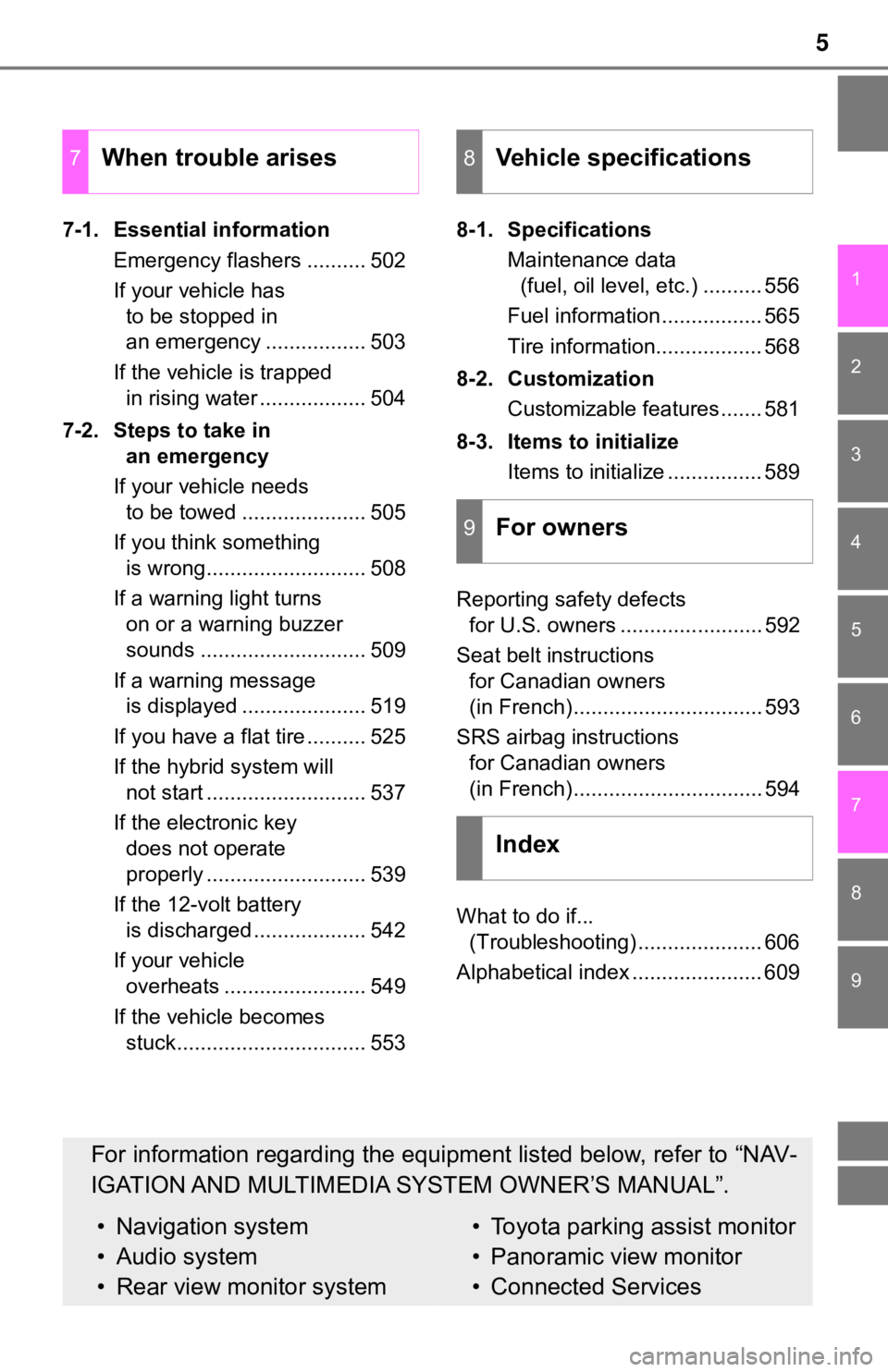
7-1. Essential informationEmergency flashers .......... 502
If your vehicle has to be stopped in
an emergency ................. 503
If the vehicle is trapped in rising water .................. 504
7-2. Steps to take in an emergency
If your vehicle needs to be towed ..................... 505
If you think something is wrong........................... 508
If a warning light turns on or a warning buzzer
sounds ............................ 509
If a warning message is displayed ..................... 519
If you have a flat tire .......... 525
If the hybrid system will not start ........................... 537
If the electronic key does not operate
properly ........................... 539
If the 12-volt battery is discharged ................... 542
If your vehicle overheats ........................ 549
If the vehicle becomes stuck................................ 553 8-1. Specifications
Maintenance data (fuel, oil level, etc.) .......... 556
Fuel information ................. 565
Tire information.................. 568
8-2. Customization Customizable features ....... 581
8-3. Items to initialize Items to initialize ................ 589
Reporting safety defects for U.S. owners ........................ 592
Seat belt instructions for Canadian owners
(in French)................................ 593
SRS airbag instructions for Canadian owners
(in French)................................ 594
What to do if... (Troubleshooting) ..................... 606
Alphabetical index ...................... 609
7When trouble arises8Vehicle specifications
9For owners
Index
For information regarding the equipment listed below, refer to “NAV-
IGATION AND MULTIMEDIA SYSTEM OWNER’S MANUAL”.
• Navigation system
• Audio system
• Rear view monitor system• Toyota parking assist monitor
• Panoramic view monitor
• Connected Services
Page 16 of 624
16Pictorial index
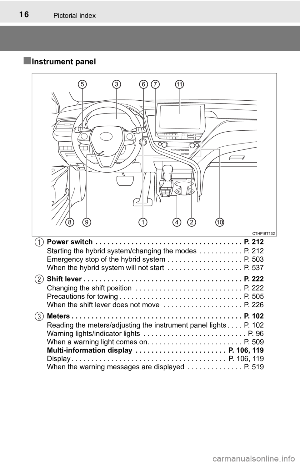
■Instrument panel
Power switch . . . . . . . . . . . . . . . . . . . . . . . . . . . . . . . . . . . . . P. 212
Starting the hybrid system/changing the modes . . . . . . . . . . . P. 212
Emergency stop of the hybrid system . . . . . . . . . . . . . . . . . . . P. 503
When the hybrid system will not start . . . . . . . . . . . . . . . . . . . P. 537
Shift lever . . . . . . . . . . . . . . . . . . . . . . . . . . . . . . . . . . . . . . . . P. 222
Changing the shift position . . . . . . . . . . . . . . . . . . . . . . . . . . . P. 222
Precautions for towing . . . . . . . . . . . . . . . . . . . . . . . . . . . . . . . P. 505
When the shift lever does not move . . . . . . . . . . . . . . . . . . . . P. 226
Meters . . . . . . . . . . . . . . . . . . . . . . . . . . . . . . . . . . . . . . . . . . . P. 102
Reading the meters/adjusting the instrument panel lights . . . . P. 102
Warning lights/indicator lights . . . . . . . . . . . . . . . . . . . . . . . . . . P. 96
When a warning light comes on . . . . . . . . . . . . . . . . . . . . . . . . P. 509
Multi-information display . . . . . . . . . . . . . . . . . . . . . . . P. 106, 119
Display . . . . . . . . . . . . . . . . . . . . . . . . . . . . . . . . . . . . . . . P. 106, 119
When the warning messages are displayed . . . . . . . . . . . . . . P. 5191
2
3
Page 67 of 624
671-2. Child safety
1
For safety and security
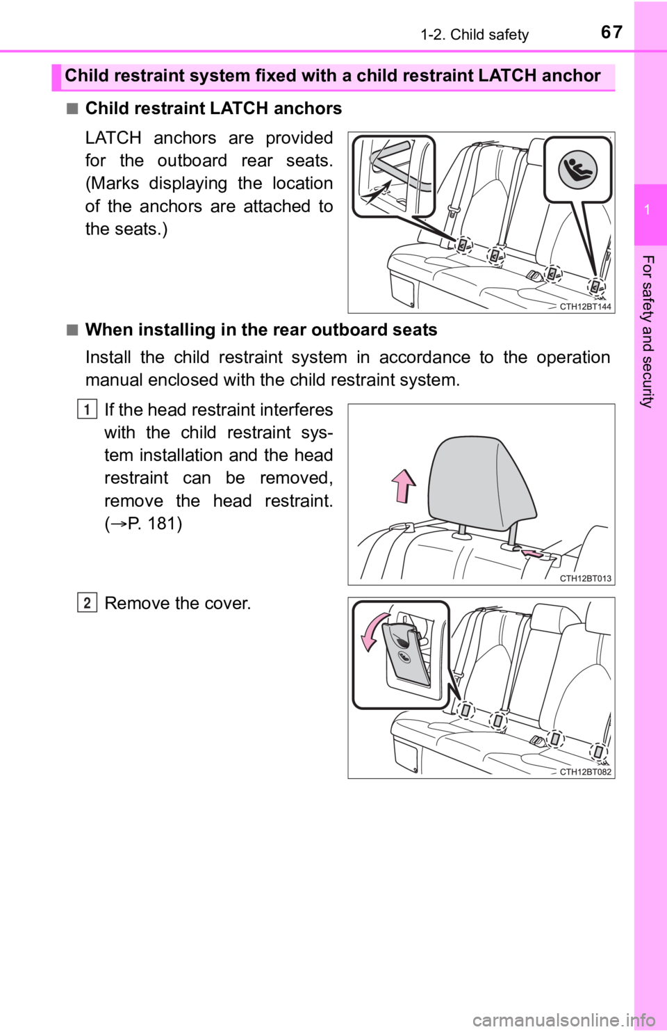
■Child restraint LATCH anchors
LATCH anchors are provided
for the outboard rear seats.
(Marks displaying the location
of the anchors are attached to
the seats.)
■When installing in the rear outboard seats
Install the child restraint system in accordance to the operation
manual enclosed with the child restraint system.
If the head restraint interferes
with the child restraint sys-
tem installation and the head
restraint can be removed,
remove the head restraint.
( P. 181)
Remove the cover.
Child restraint system fixed with a child restraint LATCH ancho r
1
2
Page 84 of 624
841-4. Hybrid system
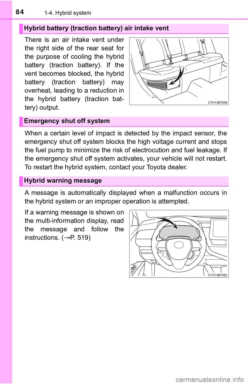
There is an air intake vent under
the right side of the rear seat for
the purpose of cooling the hybrid
battery (traction battery). If the
vent becomes blocked, the hybrid
battery (traction battery) may
overheat, leading to a reduction in
the hybrid battery (traction bat-
tery) output.
When a certain level of impact is detected by the impact sensor , the
emergency shut off system blocks the high voltage current and stops
the fuel pump to minimize the ri sk of electrocution and fuel leakage. If
the emergency shut off system activates, your vehicle will not restart.
To restart the hybrid system , contact your Toyota dealer.
A message is automatically displ ayed when a malfunction occurs in
the hybrid system or an improper operation is attempted.
If a warning message is shown on
the multi-information display, read
the message and follow the
instructions. ( P. 519)
Hybrid battery (traction battery) air intake vent
Emergency shut off system
Hybrid warning message
Page 85 of 624

851-4. Hybrid system
1
For safety and security
■If a warning light comes on, a warning message is displayed, or the 12-
volt battery is disconnected
The hybrid system may not start. In this case, try to start the system again. If
the “READY” indicator does not come on, contact your Toyota dea ler.
■ Running out of fuel
When the vehicle has run out of fuel and the hybrid system cann ot be started,
refuel the vehicle with at least enough gasoline to make the lo w fuel level
warning light ( P. 512) go off. If there is only a small amount of fuel, the
hybrid system may not be able to start. (The standard amount of fuel is about
2.3 gal. [8.8 L, 1.9 Imp. gal.] when the vehicle is on a level surface. This value
may vary when the vehicle is on a slope. Add extra fuel when th e vehicle is
inclined.)
■ Electromagnetic waves
●High voltage parts and cables on hybrid vehicles incorporate el ectromag-
netic shielding, and therefore emit approximately the same amou nt of elec-
tromagnetic waves as conventional gasoline powered vehicles or home
electronic appliances.
● Your vehicle may cause sound interference in some third party-p roduced
radio parts.
■ Hybrid battery ( traction battery)
The hybrid battery (traction battery) has a limited service life. The lifespan of
the hybrid battery (traction battery) can change in accordance with driving
style and driving conditions.
■ Starting the hybrid system in an e xtremely cold environment (AXVH70
model
*)
When the hybrid battery (traction battery) is extremely cold (b elow approxi-
mately -22°F [-30°C]) under the influence of the outside temper ature, it may
not be possible to start the hybrid system. In this case, try to start the hybrid
system again after the temperature of the hybrid battery (traction battery)
increases due to the outside temperature increase etc.
*: The model code is indicated on the Certification Label. ( P. 557)
Page 95 of 624

95
Instrument cluster2
2. Instrument clusterWarning lights and indicators .......................... 96
Gauges and meters .......... 102
Multi-information display (4.2-inch display) ............ 106
Multi-information display (7-inch display) ............... 119
Head-up display ................ 138
Energy monitor/ consumption screen ........ 144
Page 96 of 624
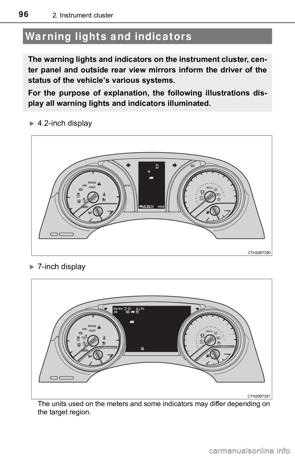
962. Instrument cluster
4.2-inch display
7-inch display
The units used on the meters and some indicators may differ depending on
the target region.
Warning lights and indicators
The warning lights and indicators on the instrument cluster, ce n-
ter panel and outside rear view mirrors inform the driver of the
status of the vehicle’s various systems.
For the purpose of explanation, t he following illustrations dis-
play all warning lights a nd indicators illuminated.
Page 102 of 624
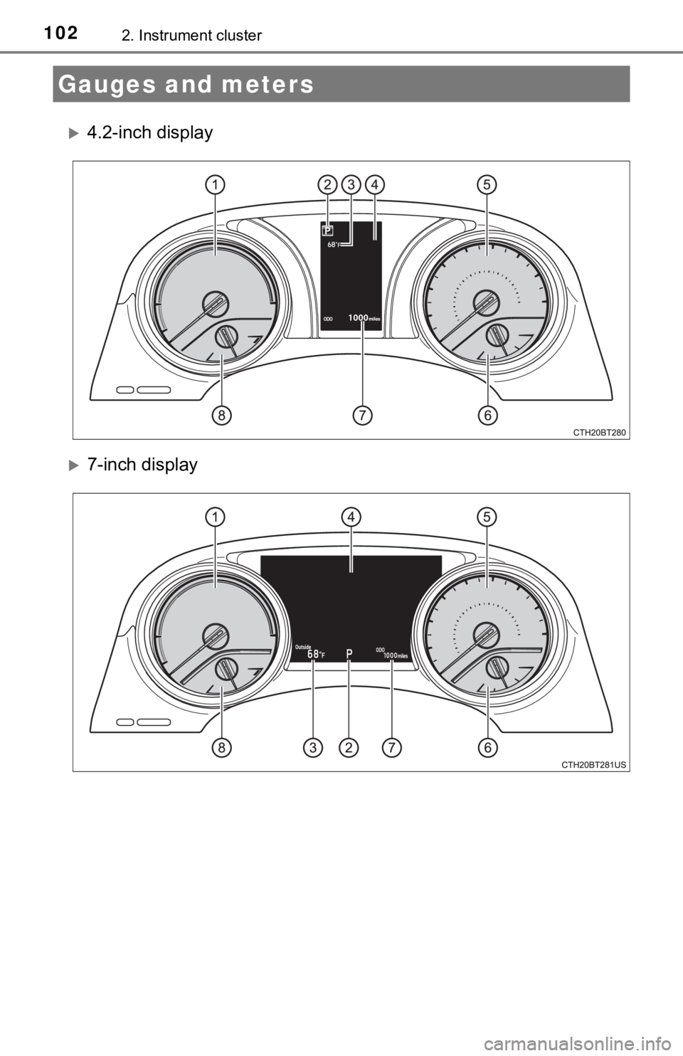
1022. Instrument cluster
4.2-inch display
7-inch display
Gauges and meters
Page 103 of 624
1032. Instrument cluster
2
Instrument cluster
Hybrid System Indicator
Displays hybrid system output or regeneration level (P. 104)
Shift position (P. 2 2 2 )
Outside temperature
Displays the outside temperature within the range of -40°F (-40 °C) to
122°F (50°C). Low outside temperat ure indicator comes on when the
ambient temperature is 37°F (3°C) or lower.
Multi-information display
Presents the driver with a variety of vehicle data ( P. 106, 119)
Displays warning messages in case of a malfunction ( P. 519)
Speedometer
Fuel gauge
Displays the fuel level. In the following situations, the actua l fuel level may
not be displayed correctly:
• After refueling only a small amount (approximately 5 L or less )
• When stopped on a hill or other slope
• When driving on a slope or around a curve
Odometer and trip meter ( P. 116, 135)
Engine coolant temperature gauge
Displays the engine coolant temperature
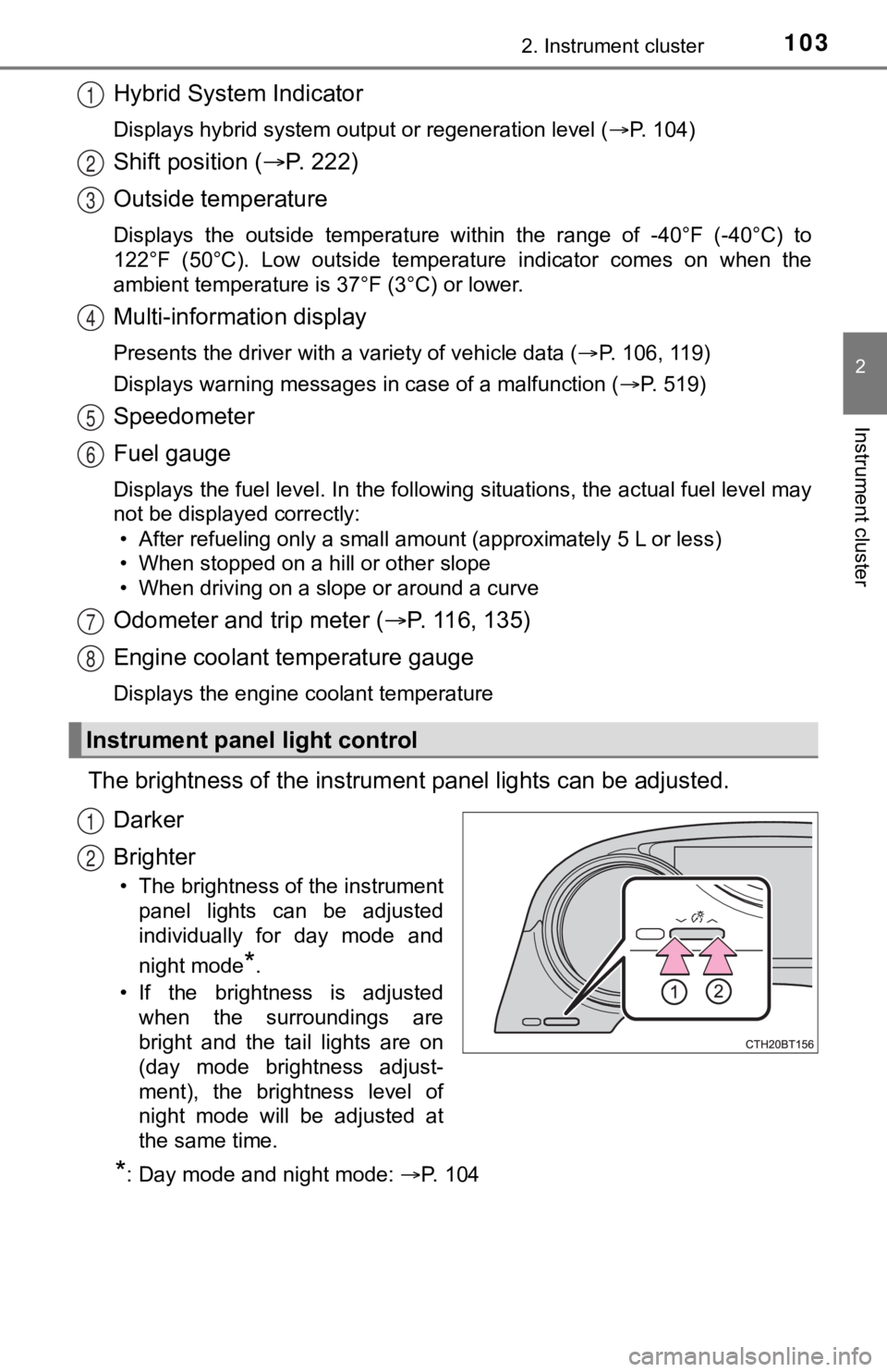
The brightness of the instrumen t panel lights can be adjusted.
Darker
Brighter
• The brightness of the instrument panel lights can be adjusted
individually for day mode and
night mode
*.
• If the brightness is adjusted when the surroundings are
bright and the tail lights are on
(day mode brightness adjust-
ment), the brightness level of
night mode will be adjusted at
the same time.
*: Day mode and night mode: P. 1 0 4
Instrument panel light control
1
2
3
4
5
6
7
8
1
2