height TOYOTA CAMRY HYBRID 2021 Owners Manual (in English)
[x] Cancel search | Manufacturer: TOYOTA, Model Year: 2021, Model line: CAMRY HYBRID, Model: TOYOTA CAMRY HYBRID 2021Pages: 624, PDF Size: 15.98 MB
Page 29 of 624
291-1. For safe use
1
For safety and security
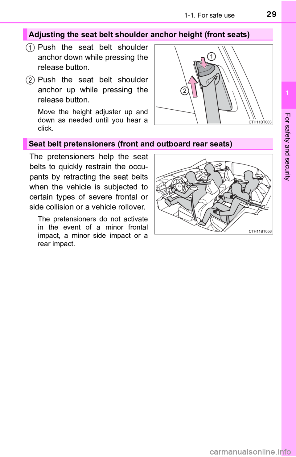
Push the seat belt shoulder
anchor down while pressing the
release button.
Push the seat belt shoulder
anchor up while pressing the
release button.
Move the height adjuster up and
down as needed until you hear a
click.
The pretensioners help the seat
belts to quickly restrain the occu-
pants by retracting the seat belts
when the vehicle is subjected to
certain types of severe frontal or
side collision or a vehicle rollover.
The pretensioners do not activate
in the event of a minor frontal
impact, a minor side impact or a
rear impact.
Adjusting the seat belt shoulder anchor height (front seats)
1
2
Seat belt pretensioners (fr ont and outboard rear seats)
Page 177 of 624
177
3
Operation of each component
3-3. Adjusting the seats
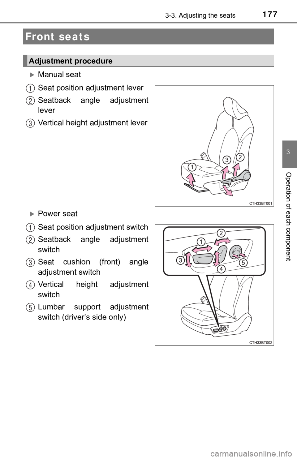
Manual seat
Seat position adjustment lever
Seatback angle adjustment
lever
Vertical height adjustment lever
Power seat
Seat position ad justment switch
Seatback angle adjustment
switch
Seat cushion (front) angle
adjustment switch
Vertical height adjustment
switch
Lumbar support adjustment
switch (driver’s side only)
Front seats
Adjustment procedure
1
2
3
1
2
3
4
5
Page 181 of 624
1813-3. Adjusting the seats
3
Operation of each component
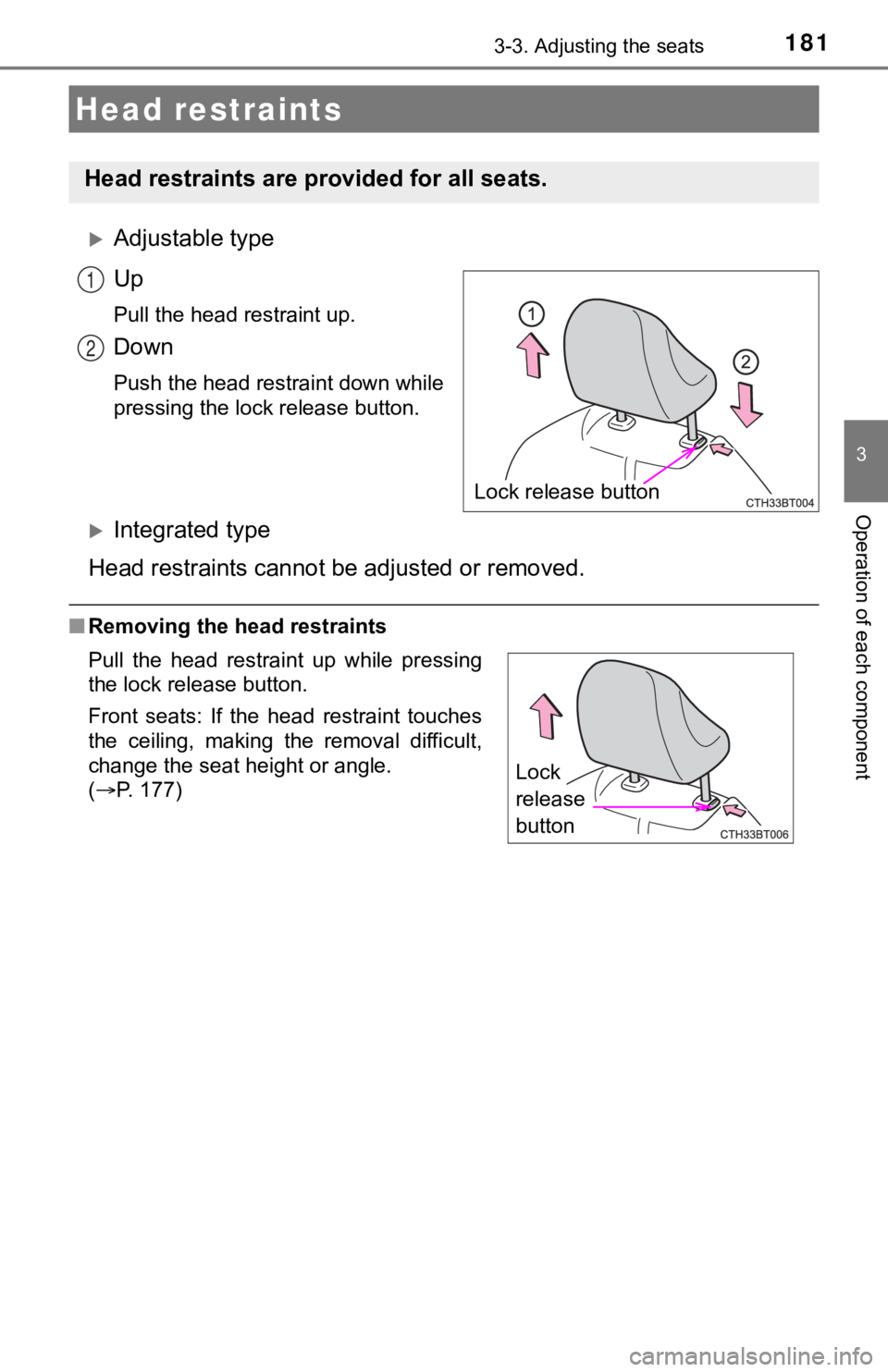
Adjustable type
Up
Pull the head restraint up.
Down
Push the head restraint down while
pressing the lock release button.
Integrated type
Head restraints cannot b e adjusted or removed.
■Removing the head restraints
Head restraints
Head restraints are provided for all seats.
Lock release button
1
2
Pull the head restraint up while pressing
the lock release button.
Front seats: If the head restraint touches
the ceiling, making the removal difficult,
change the seat height or angle.
(P. 177)
Lock
release
button
Page 182 of 624
1823-3. Adjusting the seats
■Installing the head restraints
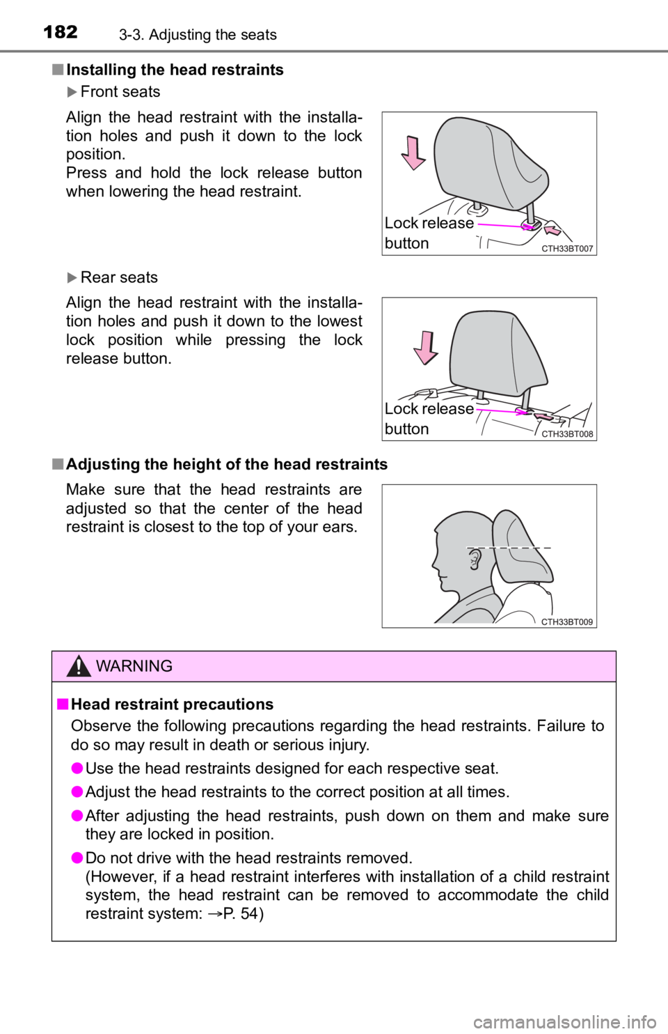
Front seats
Rear seats
■ Adjusting the height of the head restraints Align the head restraint with the installa-
tion holes and push it down to the lock
position.
Press and hold the lock release button
when lowering the head restraint.
Align the head restraint with the installa-
tion holes and push it down to the lowest
lock position while pressing the lock
release button.
Make sure that the head restraints are
adjusted so that the center of the head
restraint is closest to the top of your ears.
WARNING
■Head restraint precautions
Observe the following precautions regarding the head restraints. Failure to
do so may result in death or serious injury.
● Use the head restraints designed for each respective seat.
● Adjust the head restraints to the correct position at all times.
● After adjusting the head restraints, push down on them and make sure
they are locked in position.
● Do not drive with the head restraints removed.
(However, if a head restraint interferes with installation of a child restraint
system, the head restraint can be removed to accommodate the ch ild
restraint system: P. 54)
Lock release
button
Lock release
button
Page 185 of 624
1853-4. Adjusting the steering wheel and mirrors
3
Operation of each component
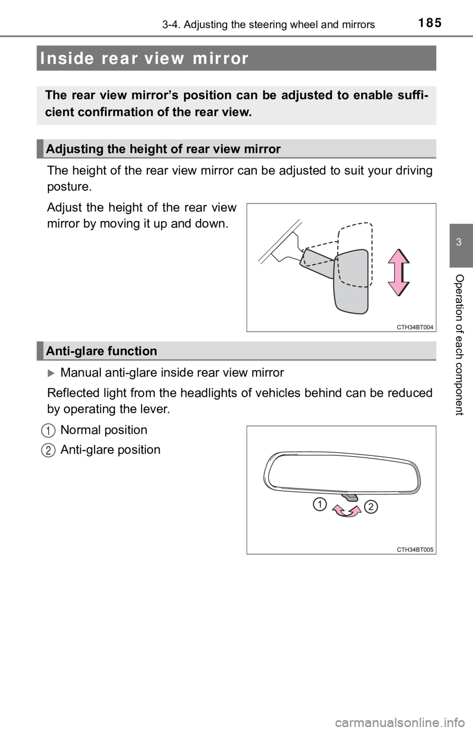
The height of the rear view mirror can be adjusted to suit your driving
posture.
Adjust the height of the rear view
mirror by moving it up and down.
Manual anti-glare inside rear view mirror
Reflected light from the headlights of vehicles behind can be r educed
by operating the lever.
Normal position
Anti-glare position
Inside rear view mirror
The rear view mirror’s position ca n be adjusted to enable suffi-
cient confirmation of the rear view.
Adjusting the height of rear view mirror
Anti-glare function
1
2
Page 272 of 624
2724-5. Using the driving support systems
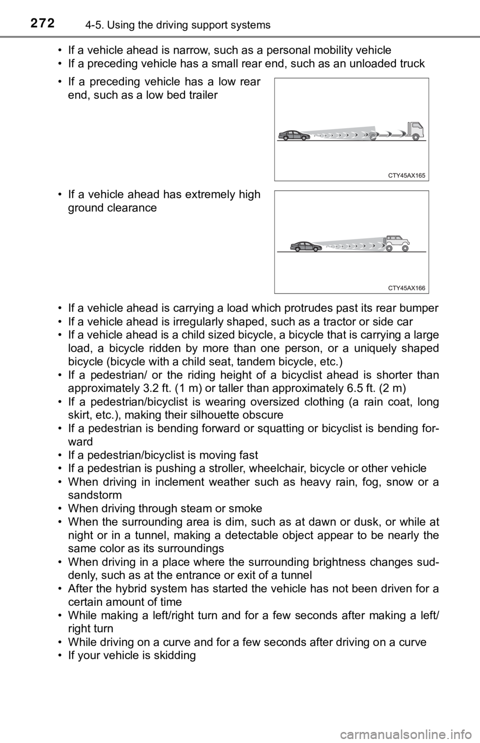
• If a vehicle ahead is narrow, such as a personal mobility vehi cle
• If a preceding vehicle has a small rear end, such as an unload ed truck
• If a vehicle ahead is carrying a load which protrudes past its rear bumper
• If a vehicle ahead is irregularly shaped, such as a tractor or side car
• If a vehicle ahead is a child sized bicycle, a bicycle that is carrying a large
load, a bicycle ridden by more than one person, or a uniquely shaped
bicycle (bicycle with a child seat, tandem bicycle, etc.)
• If a pedestrian/ or the riding height of a bicyclist ahead is shorter than
approximately 3.2 ft. (1 m) or taller than approximately 6.5 ft. (2 m)
• If a pedestrian/bicyclist is wearing oversized clothing (a rai n coat, long
skirt, etc.), making their silhouette obscure
• If a pedestrian is bending forward or squatting or bicyclist i s bending for-
ward
• If a pedestrian/bicyclist is moving fast
• If a pedestrian is pushing a stroller, wheelchair, bicycle or other vehicle
• When driving in inclement weather such as heavy rain, fog, snow or a sandstorm
• When driving through steam or smoke
• When the surrounding area is dim, such as at dawn or dusk, or while at
night or in a tunnel, making a detectable object appear to be n early the
same color as its surroundings
• When driving in a place where the surrounding brightness changes sud- denly, such as at the entrance or exit of a tunnel
• After the hybrid system has started the vehicle has not been d riven for a
certain amount of time
• While making a left/right turn and for a few seconds after mak ing a left/
right turn
• While driving on a curve and for a few seconds after driving o n a curve
• If your vehicle is skidding • If a preceding vehicle has a low rear
end, such as a low bed trailer
• If a vehicle ahead has extremely high ground clearance
Page 325 of 624

3254-5. Using the driving support systems
4
Driving
■The BSM function is operational when
●The BSM function is turned on
● Vehicle speed is greater than approximately 10 mph (16 km/h).
■ The BSM function will detect a vehicle when
●A vehicle in an adjacent lane overtakes your vehicle.
● Your vehicle overtakes a vehicle in an adjacent lane slowly.
● Another vehicle enters the detection area when it changes lanes .
■ Conditions under which the BSM function will not detect a vehic le
The BSM function is not designed to detect the following types of vehicles
and/or objects:
● Small motorcycles, bicycles, pedestrians, etc.
*
●Vehicles traveling in the opposite direction
● Guardrails, walls, signs, parked vehicles and similar stationar y objects
*
●Following vehicles that are in the same lane*
●Vehicles driving 2 lanes across from your vehicle*
●Vehicles which are being overtaken rapidly by your vehicle
*: Depending on the conditions, detection of a vehicle and/or obj ect may
occur.
■ Conditions under which the BSM function may not function correc tly
● The BSM function may not detect vehicles correctly in the following condi-
tions:
• When the sensor is misaligned due to a strong impact to the se nsor or its
surrounding area
• When driving on a road surface that is wet with standing water during bad
weather, such as heavy rain, snow, or fog
• When mud, snow, ice, a sticker, etc. is covering the sensor or surround-
ing area on the rear bumper
• When there is a significant difference in speed between your v ehicle and
the vehicle that enters the detection area
• When a vehicle is in the detection area from a stop and remains in the
detection area as your vehicle accelerates
• When driving up or down consecutive steep inclines, such as hills, a dip on the road, etc.
• When driving on roads with sharp bends, consecutive curves, or uneven
surfaces
• When multiple vehicles are approaching with only a small gap between
each vehicle
• When vehicle lanes are wide, or when driving on the edge of a lane, and
the vehicle in an adjacent lane is far away from your vehicle
• When the vehicle that enters the detection area is traveling a t about the
same speed as your vehicle
• When there is a significant difference in height between your vehicle and
the vehicle that enters the detection area
Page 359 of 624

3594-5. Using the driving support systems
4
Driving
WARNING
■To ensure the Parking Support Brake can operate properly
Observe the following precautions regarding the sensors ( P. 346). Failure
to do so may cause a sensor to not operate properly, and may cause an
accident.
● Do not modify, disassemble or paint the sensors.
● Do not replace a sensor with a part other than a genuine part.
● Do not subject a sensor or its surrounding area to a strong impact.
● Do not damage the sensors, and always keep them clean.
● If the area around a sensor is subjected to an impact, the system may not
operate properly due to the sensor being misaligned. Have the vehicle
inspected by your Toyota dealer.
■ Handling the suspension
Do not modify the suspension, as changes to the height or inclination of the
vehicle may prevent the sensors from detecting objects correctly or cause
the system to not operate or operate unnecessarily.
■ If the Parking Support Brake function (static objects) operates unnec-
essarily, such as at a railroad crossing
In the event that the Parking Support Brake function (static ob jects) oper-
ates unnecessarily, such as at a railroad crossing, brake contr ol will be can-
celed after approximately 2 seconds, allowing you to proceed forward and
leave the area, brake control can also be canceled by depressing the brake
pedal. Depressing the accelerator pedal after brake control is canceled will
allow you to proceed forward and leave the area.
Page 526 of 624
5267-2. Steps to take in an emergency
WARNING
■Using the tire jack
Observe the following precautions.
Improper use of the tire jack may cause the vehicle to suddenly fall off
the jack, leading to death or serious injury.
●Do not use the tire jack for any purpose other than replacing t ires or
installing and removing tire chains.
●Only use the tire jack that comes with this vehicle for replacing a flat
tire.
Do not use it on other vehicles, and do not use other tire jacks for
replacing tires on this vehicle.
●Put the jack properl y in its jack point.
●Do not put any part of your body under the vehicle while it is supported
by the jack.
●Do not start the hybrid system or drive the vehicle while the v ehicle is
supported by the jack.
●Do not raise the vehicle w hile someone is inside.
●When raising the vehicle, do not put an object on or under the jack.
●Do not raise the vehicle to a height greater than that required to
replace the tire.
●Use a jack stand if it is necessary to get under the vehicle.
●When lowering the vehicle, make sure that there is no-one near the
vehicle. If there are people nearby, warn them vocally before l owering.
NOTICE
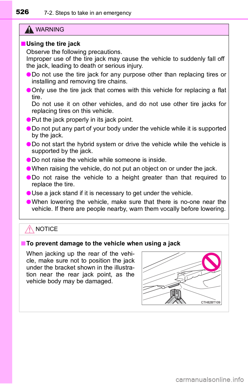
■To prevent damage to the vehicle when using a jack
When jacking up the rear of the vehi-
cle, make sure not to position the jack
under the bracket shown in the illustra-
tion near the rear jack point, as the
vehicle body may be damaged.
Page 534 of 624
5347-2. Steps to take in an emergency
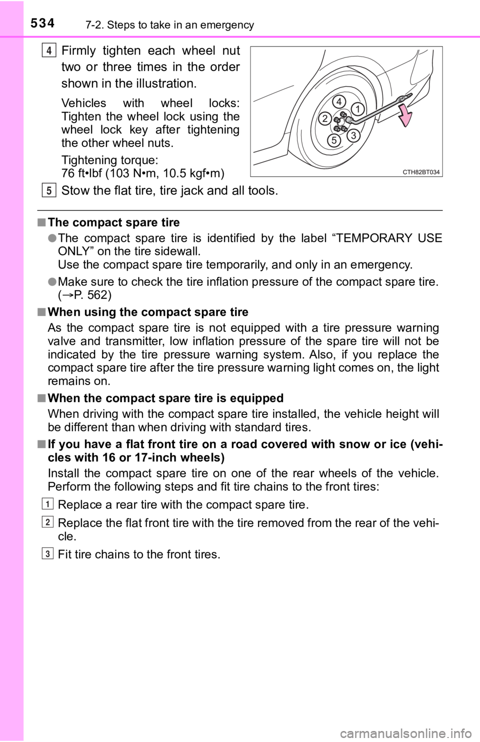
Firmly tighten each wheel nut
two or three times in the order
shown in the illustration.
Vehicles with wheel locks:
Tighten the wheel lock using the
wheel lock key after tightening
the other wheel nuts.
Tightening torque:
76 ft•lbf (103 N•m, 10.5 kgf•m)
Stow the flat tire, tire jack and all tools.
■The compact spare tire
●The compact spare tire is identified by the label “TEMPORARY US E
ONLY” on the tire sidewall.
Use the compact spar e tire temporarily, and only in an emergenc y.
●Make sure to check the tire inflation pressure of the compact spare tire.
( P. 5 6 2 )
■When using the compact spare tire
As the compact spare tire is not equipped with a tire pressure warning
valve and transmitter, low inflation pressure of the spare tire will not be
indicated by the tire pressure warning system. Also, if you rep lace the
compact spare tire after the tire pressure warning light comes on, the light
remains on.
■When the compact spa re tire is equipped
When driving with the compact spare tire installed, the vehicle height will
be different than when driving with standard tires.
■If you have a flat front tire on a road covered with snow or ic e (vehi-
cles with 16 or 17-inch wheels)
Install the compact spare tire on one of the rear wheels of the vehicle.
Perform the following steps and f it tire chains to the front tires:
Replace a rear tire with the compact spare tire.
Replace the flat front tire with the tire removed from the rear of the vehi-
cle.
Fit tire chains to the front tires.
4
5
1
2
3