condition TOYOTA CAMRY V20 1986 Service Information
[x] Cancel search | Manufacturer: TOYOTA, Model Year: 1986, Model line: CAMRY V20, Model: TOYOTA CAMRY V20 1986Pages: 2389, PDF Size: 84.44 MB
Page 2300 of 2389
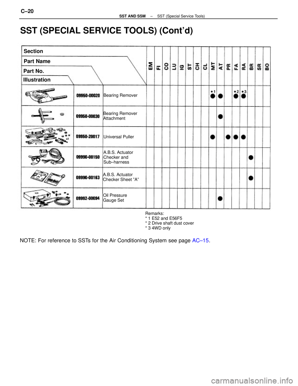
SST (SPECIAL SERVICE TOOLS) (Cont'd)
NOTE: For reference to SSTs for the Air Conditioning System see page AC±15.
Remarks:
* 1 E52 and E56F5
* 2 Drive shaft dust cover
* 3 4WD only A.B.S. Actuator
Checker and
Sub±harness
A.B.S. Actuator
Checker Sheet ºAºBearing Remover
Attachment
Oil Pressure
Gauge SetBearing Remover
IllustrationPart Name
Universal Puller
Part No.Section
± SST AND SSMSST (Special Service Tools)C±20
Page 2302 of 2389
(S51)
Straight screw plug for reverse restrict pin
Straight screw plug for shift fork shaft locking ball
Side bearing retainer set bolt
No. 2 lock ball assembly
Transmission case cover set bolt
(E56F5)
Straight screw plug
Transmission case cover set bolt
Transmission case set bolt
Transaxle case set bolt
Transfer case set bolt
Transfer right case set bolt
Shift and select lever shaft assembly set bolt
(E52)
Straight screw plug
Transaxle case cover bolt
Control shaft cover bolt
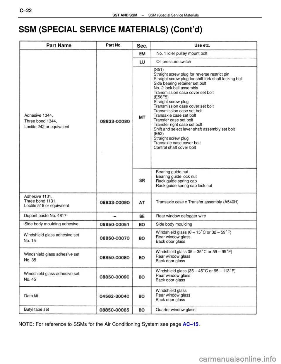
SSM (SPECIAL SERVICE MATERIALS) (Cont'd)
Windshield glass (35 ± 45°C or 95 ± 113°F)
Rear window glass
Back door glass Windshield glass 05 ± 35°C or 59 ± 95°F)
Rear window glass
Back door glassWindshield glass (0 ± 15°C or 32 ± 59°F)
Rear window glass
Back door glass
NOTE: For reference to SSMs for the Air Conditioning System see page AC±15.
Bearing guide nut
Bearing guide lock nut
Rack guide spring cap
Rack guide spring cap lock nut
Adhesive 1131,
Three bond 1131,
Loctite 518 or equivalentAdhesive 1344,
Three bond 1344,
Loctite 242 or equivalent
Windshield glass adhesive set
No. 15
Windshield glass adhesive set
No. 45Windshield glass adhesive set
No. 35Transaxle case x Transfer assembly (A540H)
Windshield glass
Rear window glass
Back door glass Side body moulding adhesiveNo. 1 idler pulley mount bolt
Rear window defogger wire Dupont paste No. 4817
Quarter window glassSide body mouldingOil pressure switch
Butyl tape set
Part NameUse etc. Part No.
Dam kitSec.
± SST AND SSMSSM (Special Service MaterialsC±22
Page 2333 of 2389
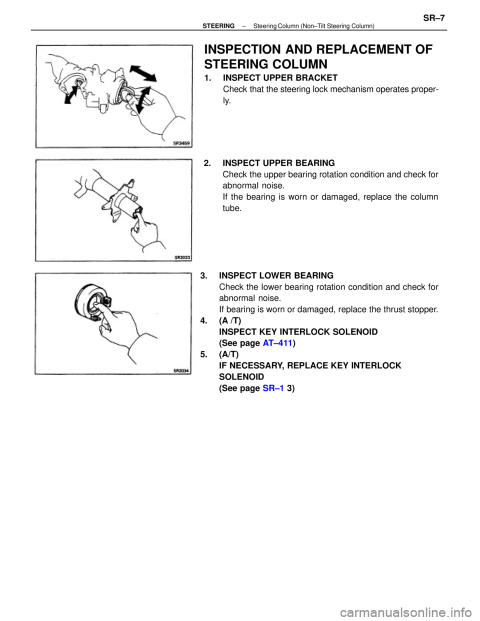
3. INSPECT LOWER BEARING
Check the lower bearing rotation condition and check for
abnormal noise.
If bearing is worn or damaged, replace the thrust stopper.
4. (A /T)
INSPECT KEY INTERLOCK SOLENOID
(See page AT±411)
5. (A/T)
IF NECESSARY, REPLACE KEY INTERLOCK
SOLENOID
(See page SR±1 3)
INSPECTION AND REPLACEMENT OF
STEERING COLUMN
1. INSPECT UPPER BRACKET
Check that the steering lock mechanism operates proper-
ly.
2. INSPECT UPPER BEARING
Check the upper bearing rotation condition and check for
abnormal noise.
If the bearing is worn or damaged, replace the column
tube.
± STEERINGSteering Column (Non±Tilt Steering Column)SR±7
Page 2343 of 2389
4. INSPECT KEY INTERLOCK SOLENOID
(See page AT±41 1)
5. IF NECESSARY, REPLACE KEY INTERLOCK
SOLENOID
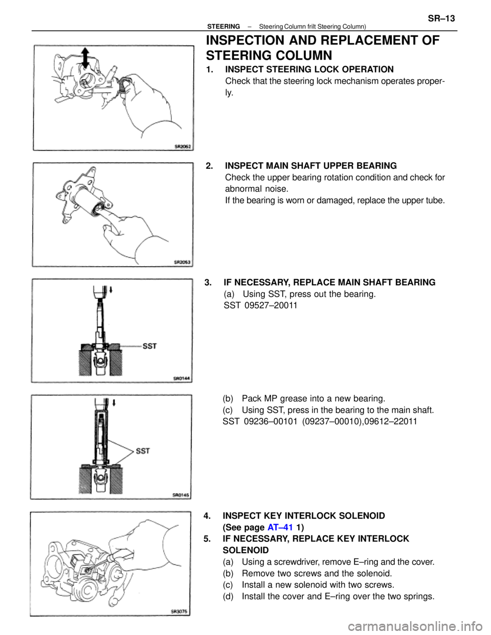
(a) Using a screwdriver, remove E±ring and the cover.
(b) Remove two screws and the solenoid.
(c) Install a new solenoid with two screws.
(d) Install the cover and E±ring over the two springs.
INSPECTION AND REPLACEMENT OF
STEERING COLUMN
1. INSPECT STEERING LOCK OPERATION
Check that the steering lock mechanism operates proper-
ly.
2. INSPECT MAIN SHAFT UPPER BEARING
Check the upper bearing rotation condition and check for
abnormal noise.
If the bearing is worn or damaged, replace the upper tube.
3. IF NECESSARY, REPLACE MAIN SHAFT BEARING
(a) Using SST, press out the bearing.
SST 09527±20011
(b) Pack MP grease into a new bearing.
(c) Using SST, press in the bearing to the main shaft.
SST 09236±00101 (09237±00010),09612±22011
± STEERINGSteering Column frilt Steering Column)SR±13
Page 2348 of 2389
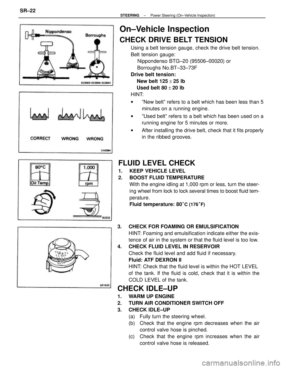
3. CHECK FOR FOAMING OR EMULSIFICATION
HINT: Foaming and emulsification indicate either the exis-
tence of air in the system or that the fluid level is too low.
4. CHECK FLUID LEVEL IN RESERVOIR
Check the fluid level and add fluid if necessary.
Fluid: ATF DEXRON II
HINT: Check that the fluid level is within the HOT LEVEL
of the tank. If the fluid is cold, check that it is within the
COLD LEVEL of the tank.
CHECK IDLE±UP
1. WARM UP ENGINE
2. TURN AIR CONDITIONER SWITCH OFF
3. CHECK IDLE±UP
(a) Fully turn the steering wheel.
(b) Check that the engine rpm decreases when the air
control valve hose is pinched.
(c) Check that the engine rpm increases when the air
control valve hose is released.
On±Vehicle Inspection
CHECK DRIVE BELT TENSION
Using a belt tension gauge, check the drive belt tension.
Belt tension gauge:
Nippondenso BTG±20 (95506±00020) or
Borroughs No.BT±33±73F
Drive belt tension:
New belt 125
+25 Ib
Used belt 80
+20 Ib
HINT:
wºNew beltº refers to a belt which has been less than 5
minutes on a running engine.
wºUsed beltº refers to a belt which has been used on a
running engine for 5 minutes or more.
wAfter installing the drive belt, check that it fits properly
in the ribbed grooves.
FLUID LEVEL CHECK
1. KEEP VEHICLE LEVEL
2. BOOST FLUID TEMPERATURE
With the engine idling at 1,000 rpm or less, turn the steer-
ing wheel from lock to lock several times to boost fluid tem-
perature.
Fluid temperature: 80
°C (176°F)
± STEERINGPower Steering (On±Vehicle Inspection)SR±22