headlights TOYOTA CAMRY V20 1986 Service Information
[x] Cancel search | Manufacturer: TOYOTA, Model Year: 1986, Model line: CAMRY V20, Model: TOYOTA CAMRY V20 1986Pages: 2389, PDF Size: 84.44 MB
Page 760 of 2389

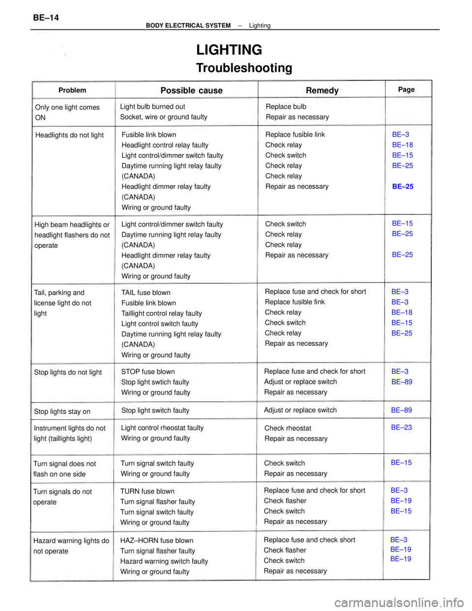
Fusible link blown
Headlight control relay faulty
Light control/dimmer switch faulty
Daytime running light relay faulty
(CANADA)
Headlight dimmer relay faulty
(CANADA)
Wiring or ground faulty
Replace fuse and check for short
Replace fusible fink
Check relay
Check switch
Check relay
Repair as necessary TAIL fuse blown
Fusible link blown
Taillight control relay faulty
Light control switch faulty
Daytime running light relay faulty
(CANADA)
Wiring or ground faulty Light control/dimmer switch faulty
Daytime running light relay faulty
(CANADA)
Headlight dimmer relay faulty
(CANADA)
Wiring or ground faultyReplace fusible link
Check relay
Check switch
Check relay
Check relay
Repair as necessary
Replace fuse and check for short
Check flasher
Check switch
Repair as necessary
Replace fuse and check short
Check flasher
Check switch
Repair as necessary HAZ±HORN fuse blown
Turn signal flasher faulty
Hazard warning switch faulty
Wiring or ground faultyCheck switch
Check relay
Check relay
Repair as necessary
Replace fuse and check for short
Adjust or replace switch
Repair as necessary
TURN fuse blown
Turn signal flasher faulty
Turn signal switch faulty
Wiring or ground faulty
LIGHTING
Troubleshooting
STOP fuse blown
Stop light swtich faulty
Wiring or ground faulty Light bulb burned out
Socket, wire or ground faulty
High beam headlights or
headlight flashers do not
operate
Light control rheostat faulty
Wiring or ground faulty Instrument lights do not
light (taillights light)Tail, parking and
license light do not
light
Turn signal switch faulty
Wiring or ground faulty
Hazard warning lights do
not operateReplace bulb
Repair as necessary
Headlights do not light
Check switch
Repair as necessaryCheck rheostat
Repair as necessary Only one light comes
ON
Turn signal does not
flash on one side
Turn signals do not
operateBE±3
BE±3
BE±18
BE±15
BE±25
Adjust or replace switch
Stop light switch faultyBE±3
BE±18
BE±15
BE±25
Stop lights do not light
Stop lights stay on
BE±3
BE±19
BE±19BE±3
BE±19
BE±15
Possible cause
BE±15
BE±25
BE±3
BE±89
RemedyProblem
BE±15BE±23 BE±89BE±25
BE±25Page
± BODY ELECTRICAL SYSTEMLightingBE±14
Page 769 of 2389

Current is led from the battery to terminal 12 of the running light relay.
Operation examples of the switch are shown below.
1. IGNITION SWITCH ºONº AND LIGHT CONTROL SWITCH ºOFFº
When the switches are set, current is led from the battery to terminal 1 of the running light relay. Also,
because continuity is made between terminal 3 and the body ground, and 5 and the body ground of
the running light relay, the taillight control relay and headlight control relay are turned on.
Then the taillights and headlights light up.
HINT: Because terminal 14 of the running light relay is not grounded at all times, the headlight dimmer
relay is off, so that the headlights light up at the low beam.
2. LIGHT CONTROL SWITCH IN ºHEADº
When the switch is set, continuity is made between terminal 4 and the body ground, and 2 and the body
ground of the running light relay. Also, because the continuity is made between terminal 5 and the body
ground, and 3 and the body ground of the running light relay at all times, the taillights and headlights
light up.
HINT: When the headlight dimmer switch is set to ºHIGHº, continuity is made between terminal 13 of
the running light relay and the body ground. Also, because continuity is made between terminal 14 of
the running light relay and the body ground, the headlight dimmer relay is turned on. Then the head-
lights go on at the high beam.
3. HEADLIGHT DIMMER SWITCH IN ºFLASHº
When the switch is set, continuity is made between terminal 6 and the body ground, and 13 and the
body ground of the running light relay. Also, because the continuity is made between terminal 5 and
the body ground, and 14 and the body ground of the running light relay, the headlights flash.
4. ENGINE STOPS (IGNITION SWITCH ºONº)
When the engine is stopped, because the continuity between terminal 5 and terminal 10 of the running
light relay remains, so the running lights also remain.
HINT: If ignition switch is turned to ºOFFº, running lights will go off because the continuity between termi-
nal 5 and terminal 10 of the running light relay is cut off.
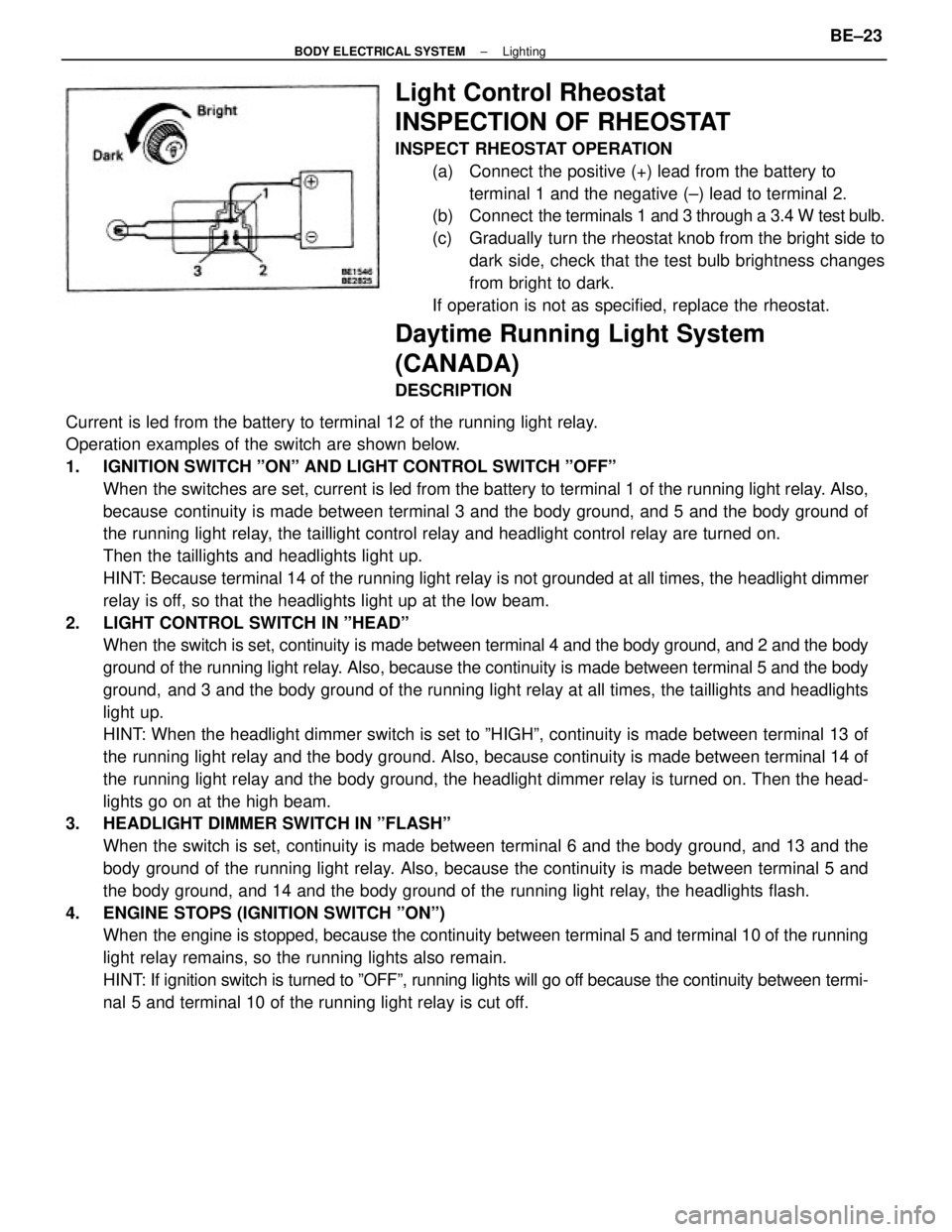
Light Control Rheostat
INSPECTION OF RHEOSTAT
INSPECT RHEOSTAT OPERATION
(a) Connect the positive (+) lead from the battery to
terminal 1 and the negative (±) lead to terminal 2.
(b) Connect the terminals 1 and 3 through a 3.4 W test bulb.
(c) Gradually turn the rheostat knob from the bright side to
dark side, check that the test bulb brightness changes
from bright to dark.
If operation is not as specified, replace the rheostat.
Daytime Running Light System
(CANADA)
DESCRIPTION
± BODY ELECTRICAL SYSTEMLightingBE±23
Page 962 of 2389

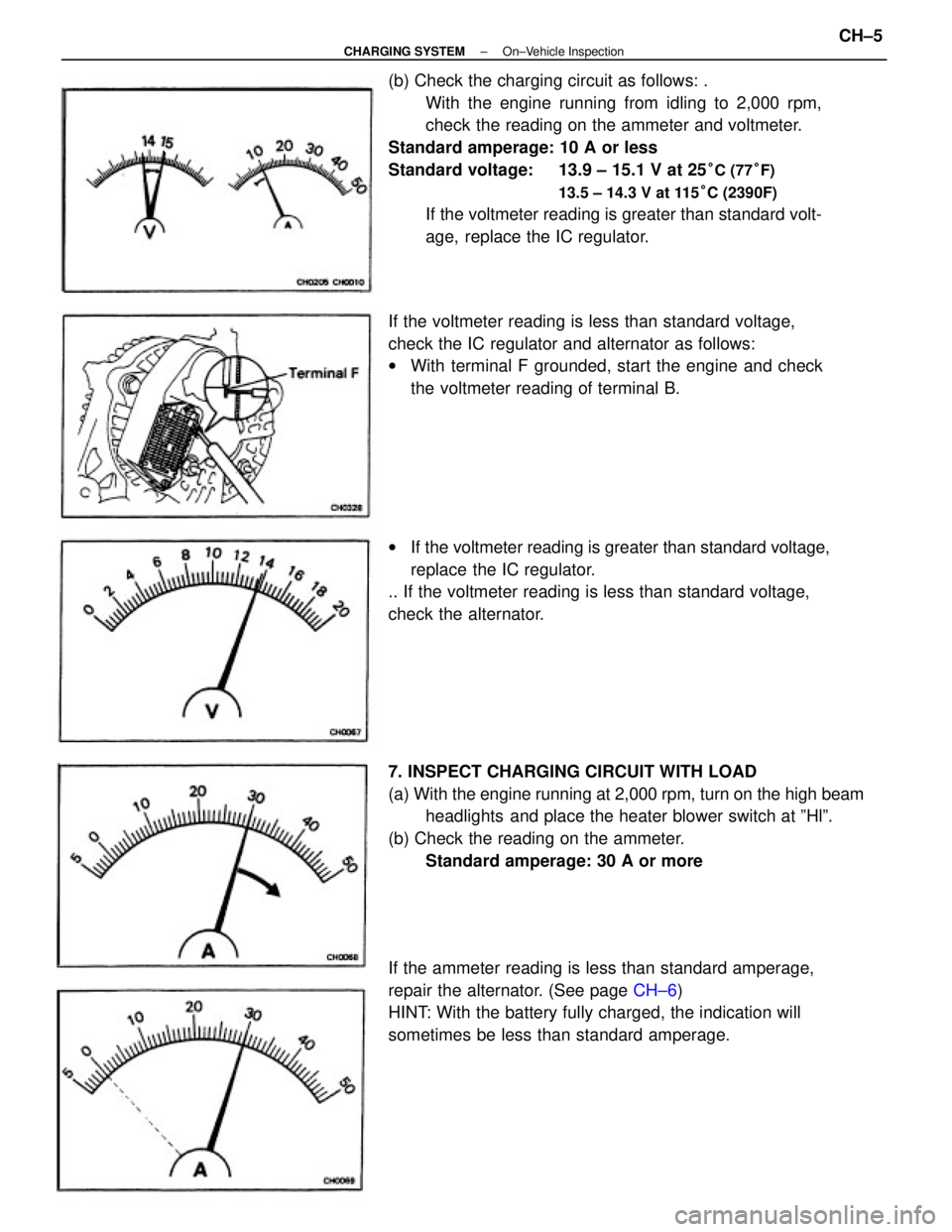
(b) Check the charging circuit as follows: .
With the engine running from idling to 2,000 rpm,
check the reading on the ammeter and voltmeter.
Standard amperage: 10 A or less
Standard voltage: 13.9 ± 15.1 V at 25
°C (77°F)
13.5 ± 14.3 V at 115°C (2390F)
If the voltmeter reading is greater than standard volt-
age, replace the IC regulator.
7. INSPECT CHARGING CIRCUIT WITH LOAD
(a) With the engine running at 2,000 rpm, turn on the high beam
headlights and place the heater blower switch at ºHlº.
(b) Check the reading on the ammeter.
Standard amperage: 30 A or more
If the ammeter reading is less than standard amperage,
repair the alternator. (See page CH±6)
HINT: With the battery fully charged, the indication will
sometimes be less than standard amperage. If the voltmeter reading is less than standard voltage,
check the IC regulator and alternator as follows:
wWith terminal F grounded, start the engine and check
the voltmeter reading of terminal B.
wIf the voltmeter reading is greater than standard voltage,
replace the IC regulator.
.. If the voltmeter reading is less than standard voltage,
check the alternator.
± CHARGING SYSTEMOn±Vehicle InspectionCH±5
Page 1914 of 2389

GENERAL MAINTENANCE
These are the maintenance and inspection items
which are considered to be the owner's responsibility,
They can be performed by the owner or he
can have then done at a service shop. These items
include those which should be checked on a daily ba-
sis, those which, in most cases, do not require
(special) tools and those which are considered to be
reasonable for the owner to perform.
Items and procedures for general maintenance are as
follows:
OUTSIDE VEHICLE
1. TIRES
(a) Check the pressure with a gauge. Adjust
if necessary.
(b) Check for cuts, damage or excessive wear.
2. WHEEL NUTS
When checking the tires, check the nuts for looseness
or for missing nuts. If necessary,
tighten them.
3. TIRE ROTATION
It is recommended that tires be rotated every
7,500 miles (12,000 km).
4. WINDSHIELD WIPER BLADES
Check for wear or cracks whenever they do not wipe
clean. Replace if necessary.
5. FLUID LEAKS
(a) Check underneath for leaking fuel, oil, water or
other fluid.
(b) If you smell gasoline fumes or notice any leak,
have the cause found and corrected.
6. DOORS AND ENGINE HOOD
(a) Check that all doors including the trunk lid and
back door operate smoothly, and that all
latches lock securely.
(b) Check that the engine hood secondary latch se-
cures the hood from opening when the prima-
ry latch is released.
INSIDE VEHICLE
7. LIGHTS
(a) Check that the headlights, stop lights, taillights,
turn signal lights, and other
lights are all working.
(b) Check the headlight aiming.8. WARNING LIGHTS AND BUZZERS
Check that all warning lights and buzzers func-
tion properly.
9. HORN
Check that it is working.
10. WINDSHIELD GLASS
Check for scratches, pits or abrasions.
11. WINDSHIELD WIPER AND WASHER
(a) Check operation of the wipers and washer.
(b) Check that the wipers do not streak.
12. WINDSHIELD DEFROSTER
Check that air comes out from the defroster out-
let when operating the heater or air conditioner
at defroster mode.
13. REAR VIEW MIRROR
Check that it is mounted securely.
14. SUN VISORS
Check that they move freely and are mounted
securely.
15. STEERING WHEEL
Check that it has the specified freeplay. Be alert
for changes in steering condition, such as hard
steering, excessive freeplay or strange noise.
16. SEATS
(a) Check that all front seat controls such as
seat adjusters, seatback recliner, etc.
operate smoothly.
(b) Check that a11 latches lock securely in
any position.
(c) Check that the locks hold securely in any
latched position.
(d) Check that the head restraints move up
and down smoothly and that the locks
hold securely in any latched position.
(e) For folding±down rear seat backs, check
that the latches lock securely.
17. SEAT BELTS
(a) Check that the seat belt system such as
buckles, retractors and anchors operate
properly and smoothly.
(b) Check that the belt webbing is not cut,
frayed, worn or damaged.
± MAINTENANCEGeneral MaintenanceMA±16