tire type TOYOTA CAMRY V20 1986 Service Information
[x] Cancel search | Manufacturer: TOYOTA, Model Year: 1986, Model line: CAMRY V20, Model: TOYOTA CAMRY V20 1986Pages: 2389, PDF Size: 84.44 MB
Page 711 of 2389

5. INSTALL FOLLOWING PARTS:
(a) Roof side inner garnish
(b) Rear seat belt anchor bolt
Torque: 440 kg±cm (32 ft±Ib, 43 N¿rn)
(c) Roof drip moulding
(d) (w/ Fixed Seat Type)
Rear seat
(e) (w/ Separate Seat Type)
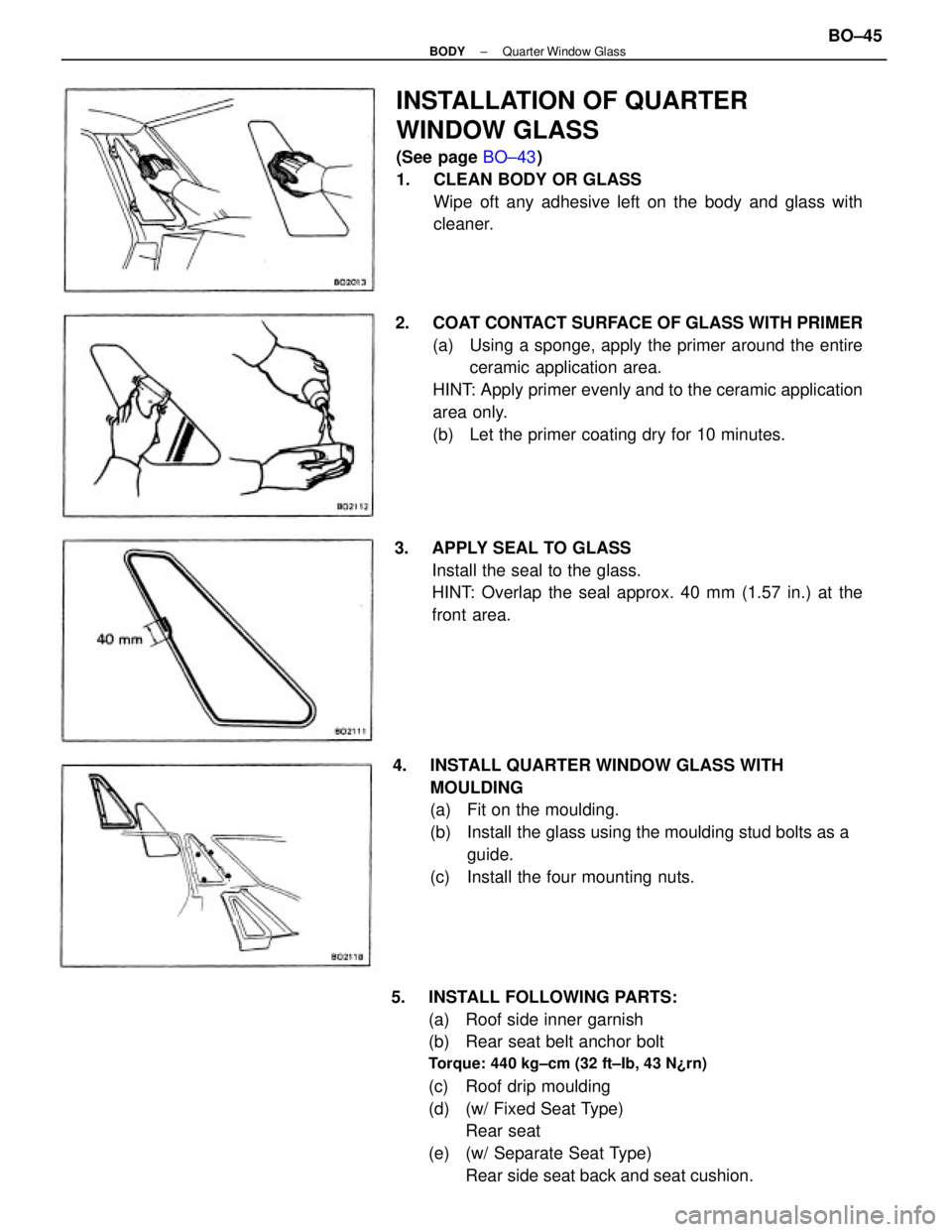
Rear side seat back and seat cushion. 2. COAT CONTACT SURFACE OF GLASS WITH PRIMER
(a) Using a sponge, apply the primer around the entire
ceramic application area.
HINT: Apply primer evenly and to the ceramic application
area only.
(b) Let the primer coating dry for 10 minutes.
4. INSTALL QUARTER WINDOW GLASS WITH
MOULDING
(a) Fit on the moulding.
(b) Install the glass using the moulding stud bolts as a
guide.
(c) Install the four mounting nuts.
INSTALLATION OF QUARTER
WINDOW GLASS
(See page BO±43)
1. CLEAN BODY OR GLASS
Wipe oft any adhesive left on the body and glass with
cleaner.
3. APPLY SEAL TO GLASS
Install the seal to the glass.
HINT: Overlap the seal approx. 40 mm (1.57 in.) at the
front area.
± BODYQuarter Window GlassBO±45
Page 1864 of 2389

PRECAUTIONS WHEN SERVICING
FULL±TIME 4WD VEHICLES
The 1990 model year full±time 4WD Camry is equipped with two
types of transaxle ± either the manual transaxle or the automatic
transaxle. The center differential system of the manual transaxle
is the mechanical lock type. The center differential
system of the automatic transaxle is a hydraulic multiplate clutch
control type. When carrying out any kind of servicing or testing
on a full±time 4WD in which the front or rear wheels are made to
rotate (braking test, speedometer test, on±vehicle wheel balanc-
ing, etc.), or when towing the vehicle, be sure to observe the pre-
cautions given below. If incorrect preparations or test procedures
are used, the test cannot be successfully carried out, and may
be dangerous as well. Therefore, before beginning any such ser-
vicing or test, be sure to check the following items:
(1) Center differential lock type
(2) Center differential mode position
(3) Whether wheels should be touching ground or jacked up
(4) Transmission gear position
(5) Maximum testing vehicle speed
(6) Maximum testing time
Also be sure to observe the following cautions:
(1) Never accelerate or decelerate the vehicle suddenly.
(2) Observe the other cautions given for each individual test.
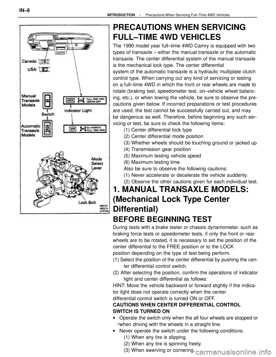
1. MANUAL TRANSAXLE MODELS:
(Mechanical Lock Type Center
Differential)
BEFORE BEGINNING TEST
During tests with a brake tester or chassis dynamometer, such as
braking force tests or speedometer tests, if only the front or rear
wheels are to be rotated, it is necessary to set the position of the
center differential to the FREE position or to the LOCK
position depending on the type of test being perform.
(1) Select the position of the center differential by pushing the cen-
ter differential control switch.
(2) After selecting the position, confirm the operations of indicator
light and center differential as follows:
HINT: Move the vehicle backward or forward slightly if the indica-
tor light does not operate correctly when the center
differential control switch is turned ON or OFF.
CAUTIONS WHEN CENTER DIFFERENTIAL CONTROL
SWITCH IS TURNED ON
wOperate the switch only when the all four wheels are stopped or
when driving with the wheels in a straight line.
wNever operate the switch under the following conditions.
(1) When any tire is slipping.
(2) When any tire is spinning freely.
(3) When swerving or cornering.
± INTRODUCTIONPrecautions When Servicing Full±Time 4WD VehiclesIN±8
Page 1865 of 2389

PRECAUTIONS WHEN SERVICING
FULL±TIME 4WD VEHICLES
The 1990 model year full±time 4WD Camry is equipped with two
types of transaxle ± either the manual transaxle or the automatic
transaxle. The center differential system of the manual transaxle
is the mechanical lock type. The center differential
system of the automatic transaxle is a hydraulic multiplate clutch
control type. When carrying out any kind of servicing or testing
on a full±time 4WD in which the front or rear wheels are made to
rotate (braking test, speedometer test, on±vehicle wheel balanc-
ing, etc.), or when towing the vehicle, be sure to observe the pre-
cautions given below. If incorrect preparations or test procedures
are used, the test cannot be successfully carried out, and may
be dangerous as well. Therefore, before beginning any such ser-
vicing or test, be sure to check the following items:
(1) Center differential lock type
(2) Center differential mode position
(3) Whether wheels should be touching ground or jacked up
(4) Transmission gear position
(5) Maximum testing vehicle speed
(6) Maximum testing time
Also be sure to observe the following cautions:
(1) Never accelerate or decelerate the vehicle suddenly.
(2) Observe the other cautions given for each individual test.
1. MANUAL TRANSAXLE MODELS:
(Mechanical Lock Type Center
Differential)
BEFORE BEGINNING TEST
During tests with a brake tester or chassis dynamometer, such as
braking force tests or speedometer tests, if only the front or rear
wheels are to be rotated, it is necessary to set the position of the
center differential to the FREE position or to the LOCK
position depending on the type of test being perform.
(1) Select the position of the center differential by pushing the cen-
ter differential control switch.
(2) After selecting the position, confirm the operations of indicator
light and center differential as follows:
HINT: Move the vehicle backward or forward slightly if the indica-
tor light does not operate correctly when the center
differential control switch is turned ON or OFF.
CAUTIONS WHEN CENTER DIFFERENTIAL CONTROL
SWITCH IS TURNED ON
wOperate the switch only when the all four wheels are stopped or
when driving with the wheels in a straight line.
wNever operate the switch under the following conditions.
(1) When any tire is slipping.
(2) When any tire is spinning freely.
(3) When swerving or cornering.
± INTRODUCTIONPrecautions When Servicing Full±Time 4WD VehiclesIN±8
Page 2269 of 2389

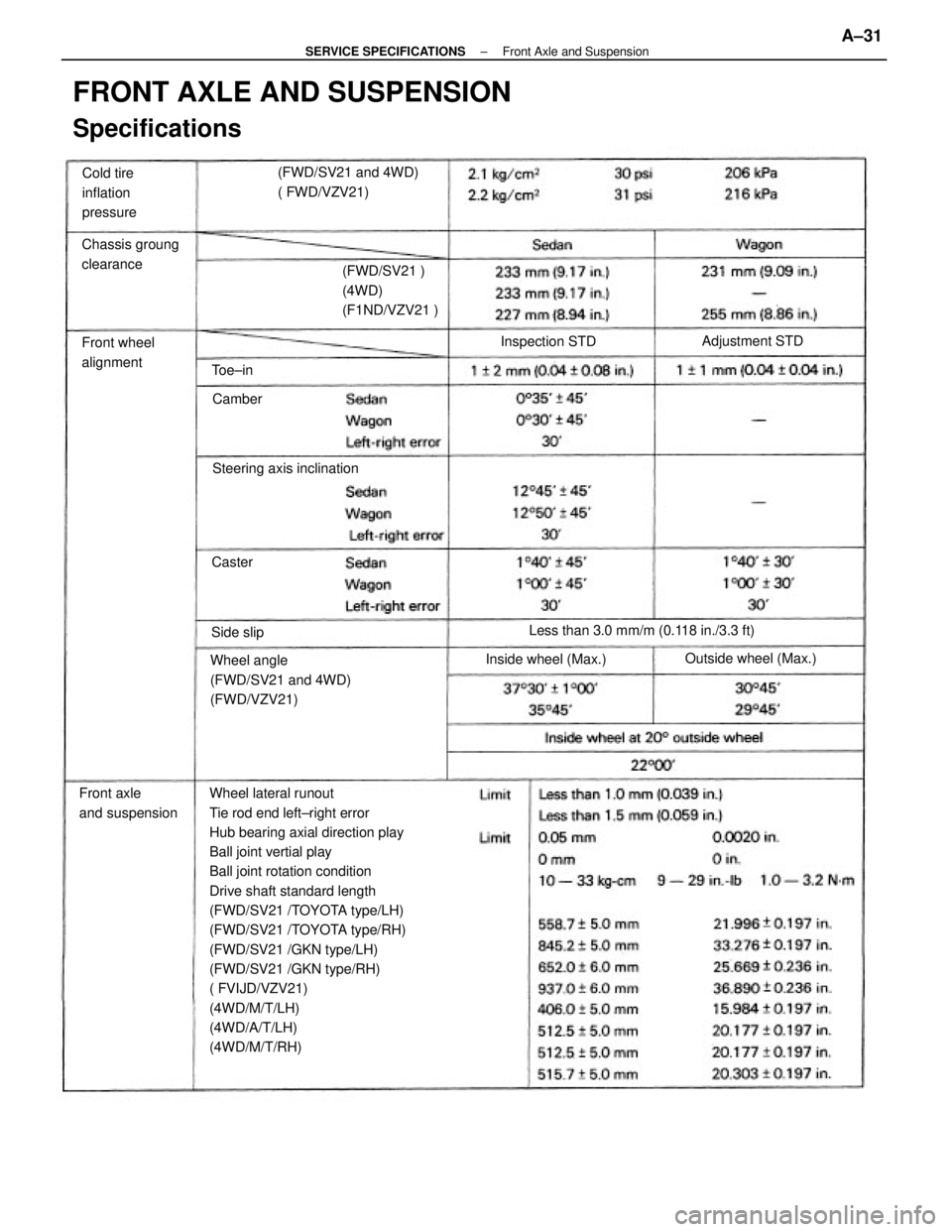
Wheel lateral runout
Tie rod end left±right error
Hub bearing axial direction play
Ball joint vertial play
Ball joint rotation condition
Drive shaft standard length
(FWD/SV21 /TOYOTA type/LH)
(FWD/SV21 /TOYOTA type/RH)
(FWD/SV21 /GKN type/LH)
(FWD/SV21 /GKN type/RH)
( FVIJD/VZV21)
(4WD/M/T/LH)
(4WD/A/T/LH)
(4WD/M/T/RH)
FRONT AXLE AND SUSPENSION
Specifications
Wheel angle
(FWD/SV21 and 4WD)
(FWD/VZV21)(FWD/SV21 and 4WD)
( FWD/VZV21)
Less than 3.0 mm/m (0.118 in./3.3 ft) (FWD/SV21 )
(4WD)
(F1ND/VZV21 )
Front axle
and suspensionChassis groung
clearance
Steering axis inclination Cold tire
inflation
pressure
Front wheel
alignment
Outside wheel (Max.)
Inside wheel (Max.)Adjustment STD
Inspection STD
Side slipCamber
Caster Toe±in
± SERVICE SPECIFICATIONSFront Axle and SuspensionA±31
Page 2352 of 2389

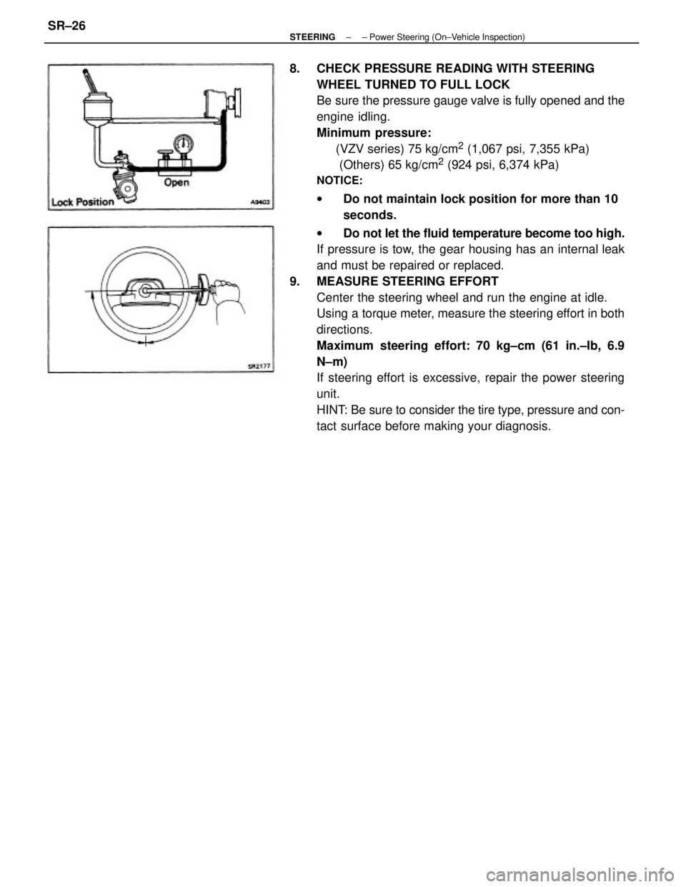
8. CHECK PRESSURE READING WITH STEERING
WHEEL TURNED TO FULL LOCK
Be sure the pressure gauge valve is fully opened and the
engine idling.
Minimum pressure:
(VZV series) 75 kg/cm
2 (1,067 psi, 7,355 kPa)
(Others) 65 kg/cm
2 (924 psi, 6,374 kPa)
NOTICE:
wDo not maintain lock position for more than 10
seconds.
wDo not let the fluid temperature become too high.
If pressure is tow, the gear housing has an internal leak
and must be repaired or replaced.
9. MEASURE STEERING EFFORT
Center the steering wheel and run the engine at idle.
Using a torque meter, measure the steering effort in both
directions.
Maximum steering effort: 70 kg±cm (61 in.±Ib, 6.9
N±m)
If steering effort is excessive, repair the power steering
unit.
HINT: Be sure to consider the tire type, pressure and con-
tact surface before making your diagnosis.
± STEERING± Power Steering (On±Vehicle Inspection)SR±26