clutch TOYOTA CELICA 1987 Service Repair Manual
[x] Cancel search | Manufacturer: TOYOTA, Model Year: 1987, Model line: CELICA, Model: TOYOTA CELICA 1987Pages: 346, PDF Size: 35.13 MB
Page 57 of 346
EFI SYSTEM - Troubleshooting
FI-23
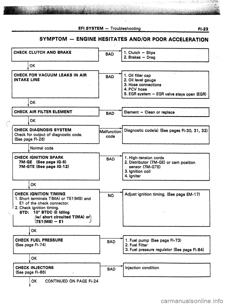
SYMPTOM - ENGINE HESITATES AND/OR POOR ACCELERATION
CHECK CLUTCH AND BRAKE .
BAD
I
I 1
1 OK
CHECK FOR VACUUM LEAKS IN AIR
INTAKE LINE
I OK BAD
I-
1. Clutch - Slips
2. Brakes - Drag
1. Oil filler cap
2. Oil level gauge
3. Hose connections :
4. PCV hose
5. EGR system - EGR valve stays open (EGR)
4
CHECK AIR FILTER ELEMENT
BAD Element - Clean or replace
I
,,: -. OK
7
. . 1 i , 1
CHECK DIAGNOSIS SYSTEM
Check for output of diagnostic code.
(See page FI-26) Malfunction
I-- code Diagnostic code(s) (See pages FI-30, 31, 32)
I
I I I J
1 Normal code
CHECK IGNITION SPARK
7M-GE (See page IO-61
7M-GTE (See page 16-12) .
BAD
I
I OK
CHECK IGNITION TIMING
1. Short terminals T(MA1 or TEl (MS) and
El of the check connector.
2. Check ignition timing.
‘i, STD: 10” BTDC @ Idling
I short circuited TiMA) or
I
I OK
CHECK FUEL PRESSURE
(See page Fl-74) 1. High-tension cords
2. Distributor (7M-GE) or cam position
sensor (7M-GTE)
3. Ignition coil
4. Igniter
NO Adjust. ignition timing. (See page EM- 17)
I
I
BAD
I
1. Fuel pump (See page Fl-73)
2. Fuel Filter
3. Fuel pressure regulator (See page Fl-84)
1
OK
CHECK INJECTORS
(See page FI-86) BAD c Injection condition
OK CONTINUED ON PAGE FI-24
Page 69 of 346
EFI SYSTEM - Troubleshooting with Volt/Ohmmeter (MA)
FI-35
. .
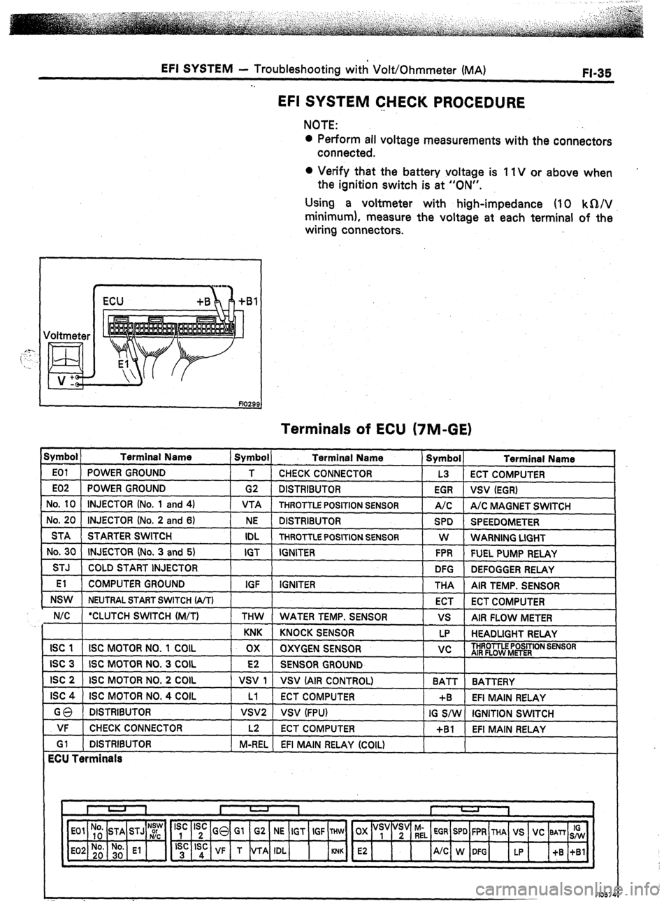
EFI SYSTEM CHECK PROCEDURE
NOTE:
l Perform all voltage measurements with the connectors
connected.
0 Verify that the battery voltage is 11V or above when
the ignition switch is at “ON”.
Using a voltmeter with high-impedance (IO kQ/V
minimum), measure the voltage at each terminal of the
wiring connectors.
I ) ECU +B
Terminals of ECU (7M-GE)
Symbol ) Terminal Name
E01 POWER GROUND
E02 POWER GROUND
No. 10 INJECTOR (No. 1 and 4)
No. 20 INJECTOR (No. 2 and 6)
STA STARTER SWITCH
No. 30 INJECTOR (No. 3 and 5)
STJ COLD START INJECTOR
El COMPUTER GROUND
NSW NEUTRAL START SWITCH (A/T)
N/C *CLUTCH SWITCH (M/T) 1 Symbol) Terminal Name
T CHECK CONNECTOR
G2 DISTRIBUTOR
VTA THROTTLE POSITION SENSOR
NE DISTRIBUTOR
IDL THROTTLE POSITION SENSOR
IGT IGNITER
IGF IGNITER
THW WATER TEMP. SENSOR Symbol
Terminal Name
L3 ECT COMPUTER
EGR
vsv (EGR)
A/C A/C MAGNET SWITCH
SPD SPEEDOMETER
W WARNING LIGHT
FPR FUEL PUMP RELAY
DFG
DEFOGGER RELAY
THA
AIR TEMP. SENSOR
ECT
ECT COMPUTER
vs AIR FLOW METER
KNK KNOCK SENSOR LP HEADLIGHT RELAY
ISC 1 ISC MOTOR NO. 1 COIL ox OXYGEN SENSOR vc THROTTLE POSITION SENSOR
AIR FLOW METER
ISC 3 ISC MOTOR NO. 3 COIL E2 SENSOR GROUND
ISC 2 ISC MOTOR NO. 2 COIL VSV 1 VSV (AIR CONTROL)
BATT BATTERY
ISC 4 ISC MOTOR NO. 4 COIL Ll ECT COMPUTER +B EFI MAIN RELAY
GQ DISTRIBUTOR VSVP VSV (FPU) IG S/W IGNITION SWITCH
VF CHECK CONNECTOR
Gl DISTRIBUTOR
ECU Terminals 1 L2 ECT COMPUTER
+Bl EFI MAIN RELAY
1 M-REL EFI MAIN RELAY (COIL)
*For cruise control
F10574
Page 70 of 346
FI-36 EFI SYSTEM - Troubleshooting with VoltjOhmmeter (MA)
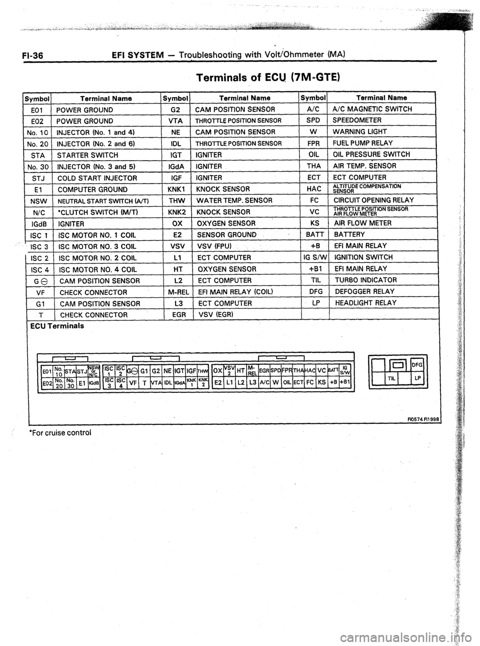
Terminals of ECU. (7M;GTE)
Symbol Terminal Name Symbol Terminal Name Symbol Terminal Name
EOI POWER GROUND G2 CAM POSITION SENSOR A/C A/C MAGNETIC SWITCH
E02 POWER GROUND VTA
THROTTLE POSITION SENSOR SPD SPEEDOMETER
No, 10 INJECTOR (No. 1 and 4)
NE CAM POSITION SENSOR W
WARNING LIGHT
No. 20 INJECTOR (No. 2 and 6) IDL
THROTTLE POSITION SENSOR FPR FUEL PUMP RELAY
STA STARTER SWITCH IGT IGNITER OIL OIL PRESSURE SWITCH
No. 30 INJECTOR (No. 3 and 5) IGdA IGNITER THA AIR TEMP. SENSOR
STJ COLD START INJECTOR
IGF IGNITER ECT ECT COMPUTER
rEl COMPUTER GROUND KNKl KNOCK SENSOR
t HAC 1 tl
NSW
NEUTRAL START SWITCH (A/T) THW WATER TEMP. S
N/C ‘CLUTCH SWITCH (M/T) KNK2 KNOCK SENSOR 1 vc ) THROTTLE
AIR
FLOW I
LTITUDE COMPENSATION
, .xNSOR
ENSOR 1 FC 1 CIRCUITOPENING RELAY I
IGdB IGNITER ox OXYGEN SENSOR KS AIR FLOW METER
ISC 1 ISC MOTOR NO. 1 COIL E2 SENSOR GROUND BATT BATTERY
r
ISC 3 ISC MOTOR NO. 3 COIL
vsv VSV (FPU) +B EFI MAIN RELAY
ISC 2 ISC MOTOR NO. 2 COIL Ll ECT COMPUTER IG S/W IGNITION SWITCH
ISC 4 ISC MOTOR NO. 4 COIL HT OXYGEN SENSOR +Bl EFI MAIN RELAY
GO CAM POSITION SENSOR L2 ECT COMPUTER TIL
TURBO INDICATOR
VF CHECK CONNECTOR M-REL
EFI MAIN RELAY (COIL) DFG DEFOGGER RELAY
Gl CAM POSITION SENSOR L3 ECT COMPUTER LP HEADLIGHT RELAY
T CHECK CONNECTOR
EGR VSV (EGR)
ECU Terminals
E2 Ll L2 L3 A/C W OIL ECT FC KS +B +Bl
+
F10574 Fll 99:
*For cruise control
Page 160 of 346
FI-126 EFI SYSTEM - Electronic Control &stem
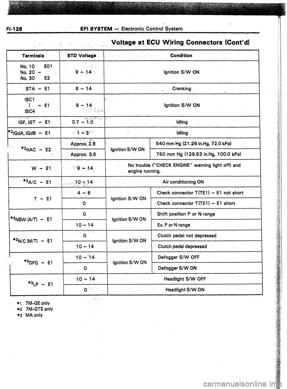
Voltage at ECU W.jring Connectors (Cont’d)
.:. .I, ,,
Termlnals
Nov
10 EOI
No. 20 -
No. 30
E2
STD Voltage
6 L ,4-,: Condition
Ignition S/W ON
STA - El
ISCI
I -El
ISC4
,, : :
IGF, IGT - .E-1
*‘IGdA, lGd8 - El
:
‘2HAC - E2 6 - 14
9 - 14
-
I, .., ,i,
o .,.- i.;&& ,; ::
:,, ;;:3%
. . 1
Approx: 2.8
- Ignition S/w ON
Approlr. -3.6 L Cranking
,
Ignition S/W ON
Idling
Idling
540 mm Hg (21.26 in.Hg, 72.0 kPa)
750 mm Hg (I 29.53 in.Hg, 100.0 kPa)
W - El ‘: :g L ;I 4
: No trouble (“CHECK ENGINE” warning light off) and
engine running.
1
*3A/C - El .,. . :.llC 1~14 Air conditioning ON
>-
T - El 4A.6
Check connector T(TE1) - El not short
Ignition S/W ON
0 Check connector TfTEl) - El short
*3NSW (A/T) - El
*3N/C Uvl/TI -
El 0
Shift position P or N range
Ignition S/W ON
IO-14 Ex. P or N range
0: Clutch pedal not depressed
- Ignition S/W ON .
IO-14 Clutch pedal depressed
..-
I 1044 1 1 Defogger S/W OFF
I
“3DFG - El
“3LP - El 0
10 - 14
j) ‘. Ignition S/W ON
Defogger S/W ON
Headlight S/W OFF
Headlight S/W ON
*I 7M-GE only
*2 7M-GTE only
*3 MA only
Page 168 of 346
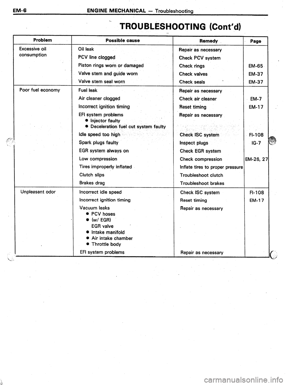
EM-6 ENGINE MECHANICAL - Troubleshooting
Problem
:- Excessive oil
consumption
Poor fuel economy
Unpleasant odor -.
TROUBLESHOOTING (Cont’d) ._
Possible cause
Oil leak
PCV line clogged
Piston rings worn or damaged
Valve stem and guide worn
Valve stem seal worn
Fuel leak
Air cleaner clogged
Incorrect ignition timing
EFI system problems
l Injector faulty
0 Deceleration fuel cut system faulty
Idle speed too high
Spark plugs faulty
EGR system always on
Low compression
Tires improperly inflated
Clutch slips
Brakes drag
Incorrect idle speed
Incorrect ignition timing
‘Vacuum leaks
0 PCV hoses
0 (w/ EGR)
EGR valve ’
0 Intake manifold
l Air intake chamber
l Throttle body
EFI system problems Remedy
Repair as necessary
Check PCV system
Check rings
Check valves
Check seals ~’
Repair as necessary
Check air cleaner
Reset timing
Repair as necessary
Check ISC system
Inspect plugs
Check EGR system
Check compression
Inflate tires to proper pressun
Troubleshoot clutch
Troubleshoot brakes
Check ISC system
Reset timing
Repair as necessary
Repair as necessary Page
EM-65
EM-37
EM-37
EM-7
EM-l 7
FI-108
IG-7
M-26, 2’
FI-108
EM-l 7
Page 319 of 346
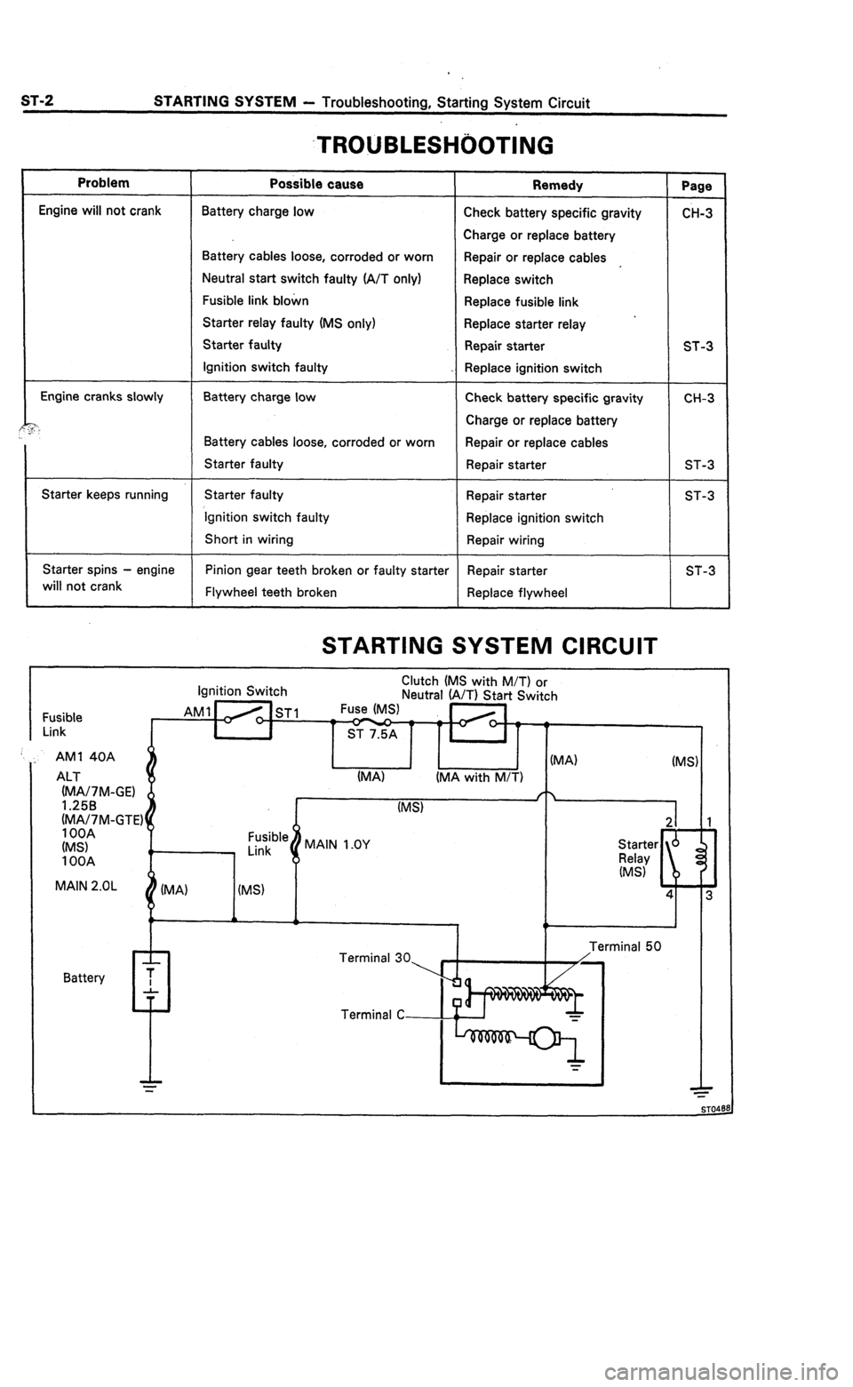
ST-2 STARTING SYSTEM - Troubleshooting, Starting System Circuit
.TROUBLESHi)OTING
Problem
Engine will not crank
Engine cranks slowly
?“.
Starter keeps running
Starter spins - engine
will not crank
Possible cause
Battery charge low
Battery cables loose, corroded or worn
Neutral start switch faulty (A/T only)
Fusible link blown
Starter relay faulty (MS only)
Starter faulty
Ignition switch faulty
Battery charge low
Battery cables loose, corroded or worn
Starter faulty
Starter faulty
‘Ignition switch faulty
Short in wiring
Pinion gear teeth broken or faulty starter
Flywheel teeth broken
Remedy
Check battery specific gravity
Charge or replace battery
Repair or replace cables
Replace switch
Replace fusible link
.
Replace starter relay
Repair starter
Replace ignition switch
Check battery specific gravity
Charge or replace battery
Repair or replace cables
Repair starter
Repair starter
Replace ignition switch
Repair wiring
Repair starter
Replace flywheel
STARTING SYSTEM CIRCUIT
Page
CH-3
ST-3
CH-3
ST-3
ST-3
ST-3
Ignition Switch Clutch (MS with M/T) or
Neutral (A/T) Start Switch
Fusible
Link AM1 Ho ST1 Fuse (MS)
t ST 7.5A
(MA/7M-GTE) ALT (MA) (MA with M/T)
(MS)
MAIN 2.OL
IMA) I IMS) I
AM1 40A
n I I PA) (MS) 1
Battery
I . I T
Page 321 of 346
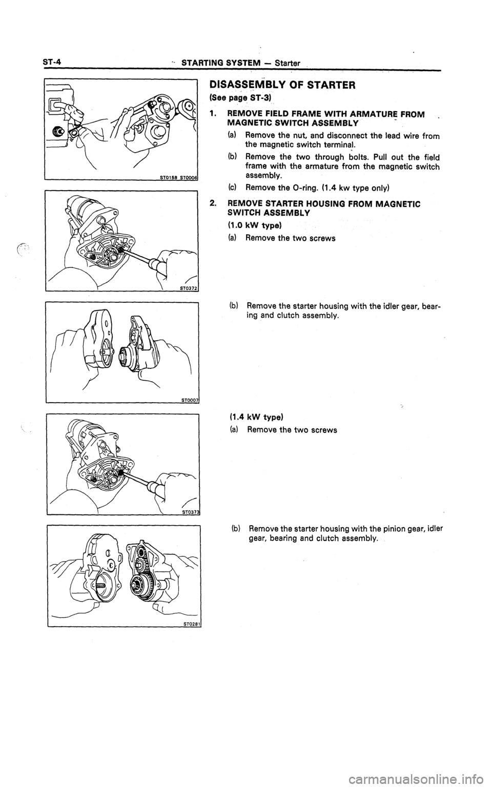
-. STARTING SYSTEM - Starter
DlSASSElViBLY OF STARTER
(See page ST-31
1. REMOVE FIELD FRAME WITH ARMATURE FROM .
MAGNETIC SWITCH ASSEhilBLY
(a) Remove the nut, and disconnect the lead wire from
the magnetic switch terminal.
(b) Remove the two through bolts. Pull out the field
frame with the armature from the magnetic switch
ST0158 ST0000 assembly.
(cl Remove the O-ring. (1.4 kw type only)
2. REM&/E STARTER HOUSING FROM MAGNETIC
SWITCH ASSEMBLY
(1 .O kW type1
(a) Remove the two screws
L
ST-4
(b) Remove the starter housing with the idler gear, bear-
ing and clutch assembly.
(1.4 kW type)
(a) Remove the two screws
(b) Remove the starter housing with the pinion gear, idler
gear, bearing and clutch assembly.
Page 323 of 346
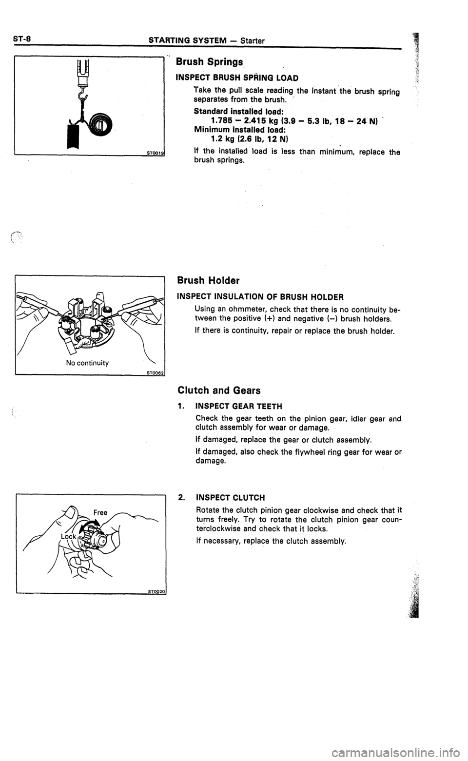
STARTING SYSTEM - Starter
No continuity
STOO6:
Brush Springs.
INSPECT BRUSH SPRING LOAD
Take the pull scale reading the instant the brush spring
separates from the brush.
Standard installed load:
1.785 - 2.415 kg (3.9 - 5.3 lb, 18 - 24 N) -
Minimum installed load:
1.2 kg (2.8 lb, 12 N)
If the installed load is less than minimum, replace the
brush springs.
Brush Holder
INSPECT INSULATION OF BRUSH HOLDER
Using an ohmmeter, check that there is no continuity be-
tween the positive (+I and negative (-1 brush holders.
If there is continuity, repair or replace the brush holder.
Clutch and Gears
1. INSPECT GEAR TEETH
Check the gear teeth on the pinion gear, idler gear and
clutch assembly for wear or damage.
If damaged, replace the gear or clutch assembly.
If damaged, also check the flywheel ring gear for wear or
damage.
2. INSPECT CLUTCH
Rotate the clutch pinion gear clockwise and check that it
turns freely. Try to rotate the clutch pinion gear coun-
terclockwise and check that it locks.
If necessary, replace the clutch assembly.
Page 325 of 346
STARTING SYSTEM - Starter
Bearing
-
‘Clutch Assembly
STOPB:
Pinion Gear
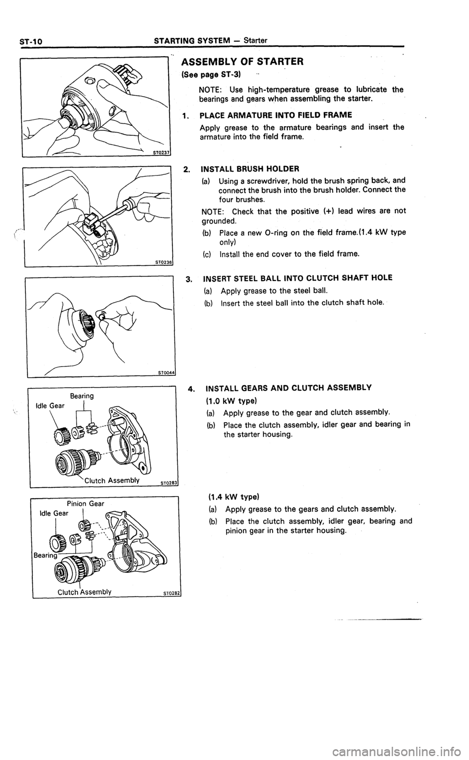
ASSEMBLY OF STARTER
(See page ST-31 --
NOTE: Use high-temperature grease to lubricate the
bearings and gears when assembling the starter.
PLACE ARMATURE INTO FIELD FRAME
_
Apply grease to the armature bearings and insert the
armature into the field frame.
INSTALL BRUSH HOLDER
(a) Using a screwdriver, hold the brush spring back, and
connect the brush into the brush holder. Connect the
four brushes.
NOTE: Check that the positive (+I lead wires are not
grounded.
(b) P’x; a new O-ring on the field frame.ll.4 kW type
(c) Install the end cover to the field frame.
INSERT STEEL BALL INTO CLUTCH SHAFT HOLE
(a) Apply grease to the steel ball.
(b)
Insert the steel ball into the clutch shaft hole.
INSTALL GEARS AND CLUTCH ASSEMBLY
(1.0 kW type)
(a) Apply grease to the gear and clutch assembly.
(b)
Place the clutch assembly, idler gear and bearing in
the starter housing.
(1.4 kW type)
(a) Apply grease to the gears and clutch assembly.
(b) Place the clutch assembly, idler gear, bearing and
pinion gear in the starter housing.
Clutchkssembly
Page 327 of 346
ST0406 ST015
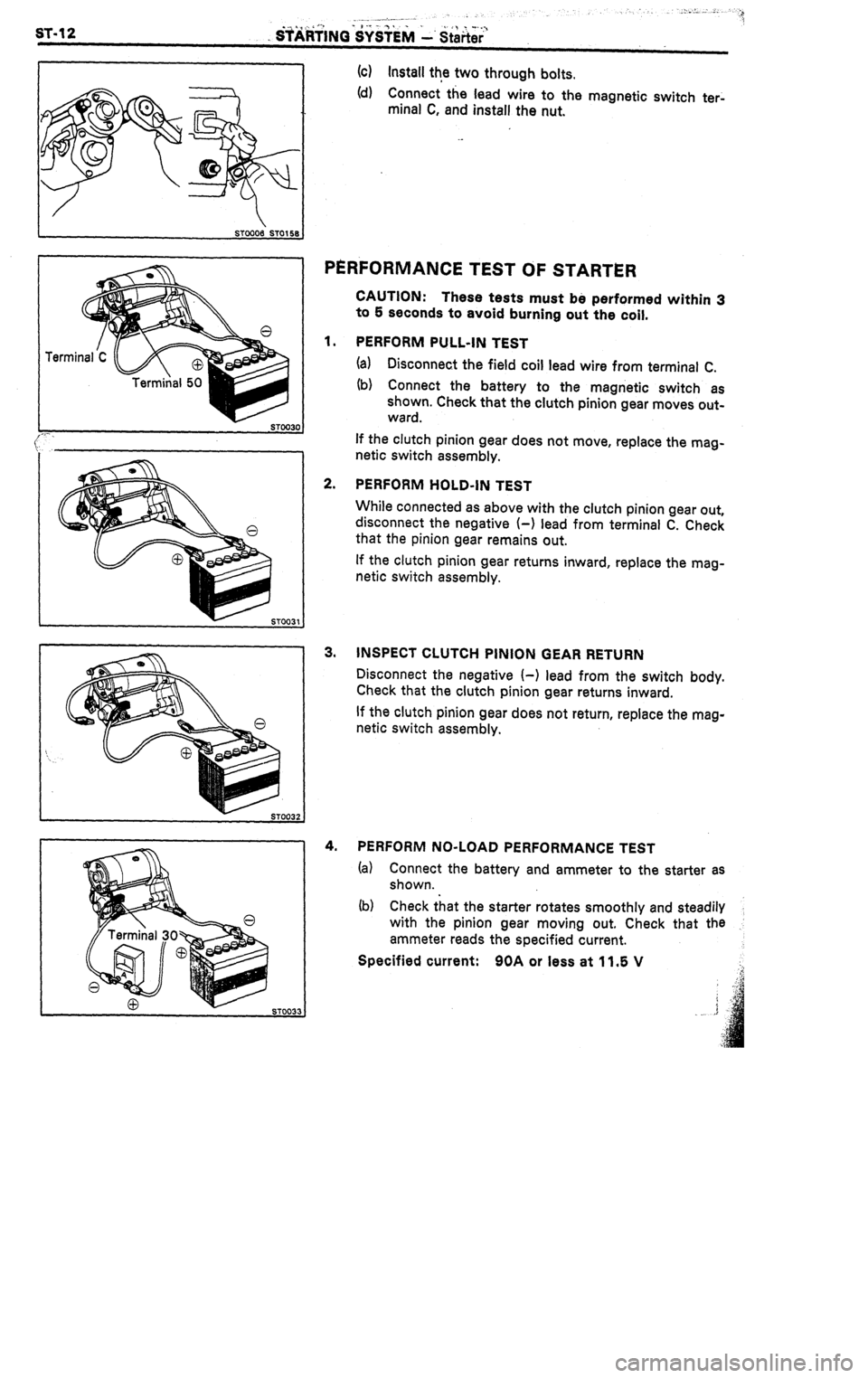
ST0033 (c) Install
the two through bolts.
(d) Connect the lead wire to the magnetic switch
ter-
minal C, and install the nut.
PERFORMANCE TEST OF STARTER
CAUTION:
These tests must be performed within 3
to 5 seconds to avoid burning out the coil.
PERFORM PULL-IN TEST
(a) Disconnect the field coil lead wire from terminal C.
(b) Connect the battery to the magnetic switch as
shown. Check that the clutch pinion gear moves out-
ward.
If the clutch pinion gear does not move, replace the mag-
netic switch assembly.
PERFORM HOLD-IN TEST
While connected as above with the clutch pinion gear out,
disconnect the negative (-1 lead from terminal C. Check
that the pinion gear remains out.
If the clutch pinion gear returns inward, replace the mag-
netic switch assembly.
INSPECT CLUTCH PINION GEAR RETURN
Disconnect the negative I-1 lead from the switch body.
Check that the clutch pinion gear returns inward.
If the clutch pinion gear does not return, replace the mag-
netic switch assembly.
PERFORM NO-LOAD PERFORMANCE TEST
(a) Connect the battery and ammeter to the starter as
shown.
(b) Check that the starter rotates smoothly and steadily
with the pinion gear moving out. Check that the
ammeter reads the specified current.
Specified current: 90A or less at 11.5 V