ground clearance TOYOTA CELICA 1987 Service Repair Manual
[x] Cancel search | Manufacturer: TOYOTA, Model Year: 1987, Model line: CELICA, Model: TOYOTA CELICA 1987Pages: 346, PDF Size: 35.13 MB
Page 175 of 346
ENGINE MECHANICAL &Engine Tune-up
EM-1 3
1
6. REMOVE CYLlNDER HEAD cOVERS
. .
(a) Remove the accelerator link.
(b) Disconn.ect the No.3 PCV hose.
(c) Remove the cylinder. head covers.
..:
s
’ .
*.
- ,; f...C?‘
;
.7. MEASURE VALVE CLEARANCE
.~. :. 1See+tep 3 oti page EM-91 3
6: ‘ADJUST VALVE CLEARANCE
j:
’ :
ISee ,tep 4 on pages EML9, 10)
: . i’... ..a .
; “.
~ ‘,
.
>*-* r-2. i.:
I / ‘.. . . 9. RFCHECK’ VALVE CLEARANCE
,y
10. INSTALL CYLiNDER HEAD COVERS
(See pages EM-59,601 ,_ .:
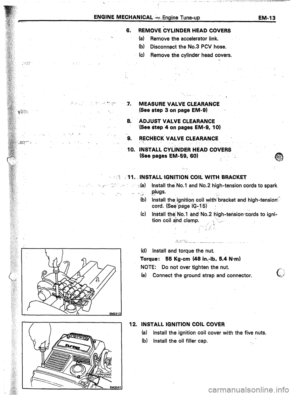
, ,-‘G j i rl.1. IN&ALL.lGNITION COIL WITH BRACKET
< .‘. ,_ ..- ,, ,,C’
:,la) Install theNo. and No.2 high-tension cords to spark
.. :I
l$w. .
._ i
$) &tall the ignition’coil withbracket and high-tension;.
cord. (Seepage I’C-,y 5)’ ;
(c) Install the No.‘l and No.2 high-tensioncords to igni-
tion coil and clamp. ,. ‘. “-. _
.;;
‘. ;
6, ..: ,-
.: .,,.. ‘y,’ I,.
(d) Install and torque the nut.
Torque : 55 Kg-cm (48 in..-lb, 5.4 Nnrn)
NOTE: Do not over tighten the nut.
(e) Connect the ground strap and connector.
12. INSTALL IGNITION COIL COVER
(a) Install the ignition coil cover with the five nuts.
fb) Install the oil filler cap.
Page 211 of 346
ENGINE MECHANICAL - Cylinder Head
SST
Snap Ring
EM063
82
(f) $u;ily heat the cylinder head to approti; “90°C
0
*
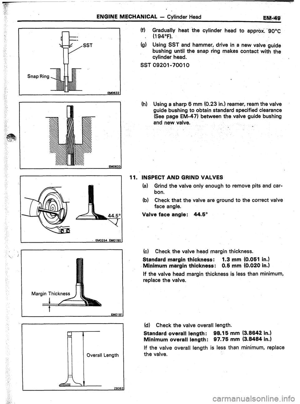
(g) Using SST and hammer, drive in a new valve guide
bushing until the snap ring makes contact with the
cylinder head.
SST 09201-70010
Overall Length
II
[r
_-
2606.
-- ,
:,”
(h) Using a sharp 6 mm (0.23 in.) reamer, ream the valve
guide bushing to obtain standard specified clearance
(See page EM-471 between the.valve guide bushing
and new .valve.
11. INSPECT AND GRIND VALVES
(a) Grind the valve only enough to remove pits and car-
bon.
(b) Check that the valve are ground to the correct valve
face angle.
Valve face angle: 44.5”
(c) Check the valve head margin thickness.
Standard margin thickness: 1.3 mm (0.051 in.)
Minimum margin thickness: 0.5 mm (0.020 in.)
If the valve head margin thickness is less than minimum,
replace the valve.
(d) Check the valve overall length.
Standard overall length: 98.15 mm (3.8842 in.)
Minimum overall length: 97.75 mm (3.8484 in.1
If the valve overall length is less than minimum, replace
the valve.
Page 219 of 346
ENGINE MECHANICAL - Cylinder Head
EM-67
EM302
EM2921
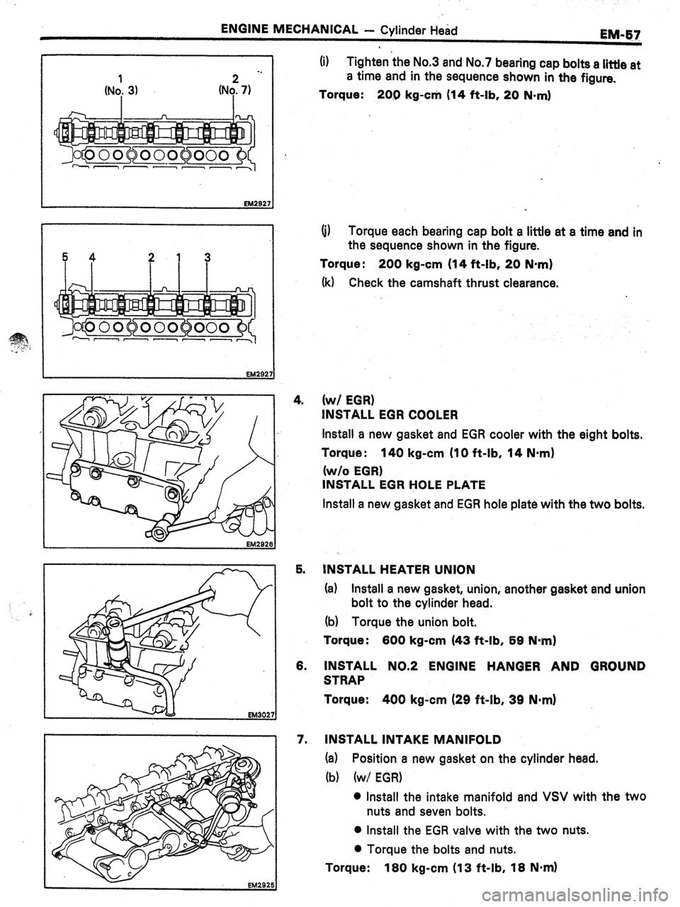
(i) Tighten the No.3 and No.7 bearing cap bolts a little at
a time and in the sequence shown in the figure.
Torque:
20.0 kg-c* (14 ft-lb, 20 N-ml
(i) Torque each bearing cap bolt a little at a time and in
the sequence shown in the figure.
Torque : 200 kg-cm (14 ft-lb, 20 N-m)
(k) Check the camshaft thrust clearance.
4.
(w/ EGR)
INSTALL EGR COOLER
Install a new gasket and EGR cooler with the eight bolts.
Torque :
140 kg-cm (IO ft-lb, 14 Nmrn)
(w/o EGR)
INSTALL EGR HOLE PLATE
Install a new gasket and EGR hole plate with the two bolts.
5. INSTALL HEATER UNION
(a) Install a new gasket, union, another gasket and union
bolt to the cylinder head.
(b) Torque the union bolt.
Torque:
600 kg-cm (43 ft-lb, 59 N-m)
6. INSTALL NO.2 ENGINE HANGER AND GROUND
STRAP
Torque:
400 kg-cm (29 ft-lb, 39 N-m)
7. INSTALL INTAKE MANIFOLD
(a) Position a new gasket on the cylinder head.
(b) (w/ EGR)
0 Install the intake manifold and VSV with the two
nuts and seven bolts.
l Install the EGR valve with the two nuts.
l Torque the bolts and nuts.
Torque: 180 kg-cm (13 ft-lb, 18 Nnrn)